View
Page 113
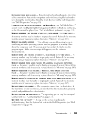
... WORD LOGIC FAILURE AT ADDRESS, READ VALUE EXPECTING VALUE - Run the System Set tests in the Dell Diagnostics (see "Contacting Dell" on page 147). L I C E N S E D C O N T E N T I S N O T A C C E S S I B L E I N M E D I A D I O N E R R O R - K E Y B O A R D S T U C K KEY F A I V E - N O B O O T S E C T O R O N H A R D D R I L U R E - Try to run the program again. Reinstall the memory modules and, if necessary, replace them (see "Dell MediaDirect problems" on page 147). A memory module may be faulty or improperly seated.
... WORD LOGIC FAILURE AT ADDRESS, READ VALUE EXPECTING VALUE - Run the System Set tests in the Dell Diagnostics (see "Contacting Dell" on page 147). L I C E N S E D C O N T E N T I S N O T A C C E S S I B L E I N M E D I A D I O N E R R O R - K E Y B O A R D S T U C K KEY F A I V E - N O B O O T S E C T O R O N H A R D D R I L U R E - Try to run the program again. Reinstall the memory modules and, if necessary, replace them (see "Dell MediaDirect problems" on page 147). A memory module may be faulty or improperly seated.

View
Page 157
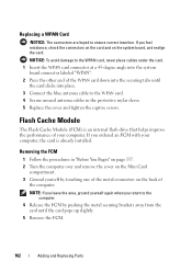
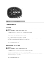
Adding and Replacing Parts 157 2 1 1 metal securing tabs (2) 2 WLAN card Replacing a WLAN Card NOTICE: The connectors are keyed to the WLAN card, never place cables under the card. 1 Insert the WLAN card connector at a 45-degree angle into the system board connector labeled "WLAN". 2 Press the other end of the WLAN card down into the securing tabs until the card clicks into place. NOTICE: To avoid damage to ensure correct insertion. If you feel resistance, check the connectors on the card and on the system board, and realign the card.
Adding and Replacing Parts 157 2 1 1 metal securing tabs (2) 2 WLAN card Replacing a WLAN Card NOTICE: The connectors are keyed to the WLAN card, never place cables under the card. 1 Insert the WLAN card connector at a 45-degree angle into the system board connector labeled "WLAN". 2 Press the other end of the WLAN card down into the securing tabs until the card clicks into place. NOTICE: To avoid damage to ensure correct insertion. If you feel resistance, check the connectors on the card and on the system board, and realign the card.

View
Page 160
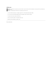
NOTICE: To avoid damage to ensure correct insertion. If you feel resistance, check the connectors on the card and on the system board, and realign the card. 2 1 1 metal securing tabs (2) 2 WWAN card Replacing a WWAN Card NOTICE: The connectors are keyed to the WWAN card, never place cables under the card. 1 Insert the WWAN card connector at a 45-degree angle into the system board connector labeled "WWAN". 2 Press the other end of the WWAN card down into the securing tabs until the card clicks into place. 160 Adding and Replacing Parts
NOTICE: To avoid damage to ensure correct insertion. If you feel resistance, check the connectors on the card and on the system board, and realign the card. 2 1 1 metal securing tabs (2) 2 WWAN card Replacing a WWAN Card NOTICE: The connectors are keyed to the WWAN card, never place cables under the card. 1 Insert the WWAN card connector at a 45-degree angle into the system board connector labeled "WWAN". 2 Press the other end of the WWAN card down into the securing tabs until the card clicks into place. 160 Adding and Replacing Parts
View
Page 162
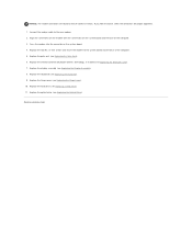
... into place. 3 Connect the blue antenna cable to ensure correct insertion. Removing the FCM 1 Follow the procedures in the protective mylar sleeve. 5 Replace the cover and tighten the captive screws. If you feel resistance, check the connectors on the card and on the back of your computer, the... card is already installed. Replacing a WPAN Card NOTICE: The connectors are keyed to the WPAN card. 4 Secure unused antenna cables in "Before You Begin" on page 137. 2 Turn the computer over and...
... into place. 3 Connect the blue antenna cable to ensure correct insertion. Removing the FCM 1 Follow the procedures in the protective mylar sleeve. 5 Replace the cover and tighten the captive screws. If you feel resistance, check the connectors on the card and on the back of your computer, the... card is already installed. Replacing a WPAN Card NOTICE: The connectors are keyed to the WPAN card. 4 Secure unused antenna cables in "Before You Begin" on page 137. 2 Turn the computer over and...
Service Manual
Page 40
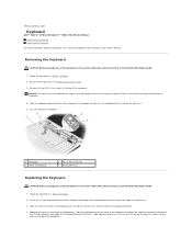
... the safety instructions in the Product Information Guide. 1. Remove the four M2 x 3-mm screws at the top of the keyboard. NOTICE: The key caps on the palm rest. 5. Align the notch at the top of the keyboard with the tab on the palm rest, and then lower the...the keyboard are fragile, easily dislodged, and time-consuming to replace. Slide the keyboard toward the back of the palm rest. Back to Contents Page Keyboard Dell™ Vostro™ 1700 and Inspiron™ 1720/1721 Service Manual Removing the Keyboard Replacing the Keyboard For more information about the keyboard, see Removing ...
... the safety instructions in the Product Information Guide. 1. Remove the four M2 x 3-mm screws at the top of the keyboard. NOTICE: The key caps on the palm rest. 5. Align the notch at the top of the keyboard with the tab on the palm rest, and then lower the...the keyboard are fragile, easily dislodged, and time-consuming to replace. Slide the keyboard toward the back of the palm rest. Back to Contents Page Keyboard Dell™ Vostro™ 1700 and Inspiron™ 1720/1721 Service Manual Removing the Keyboard Replacing the Keyboard For more information about the keyboard, see Removing ...
Service Manual
Page 42
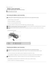
... Computer Base). Use a plastic scribe to Contents Page Battery Latch Assembly Dell™ Vostro™ 1700 and Inspiron™ 1720/1721 Service Manual Removing the Battery Latch Assembly Replacing the Battery Latch Assembly Removing the Battery Latch Assembly CAUTION: Before you begin the following procedure, ...battery release button with the slot on the guide post of the button to ensure proper installation when the button is keyed to be easily misplaced. Replace the computer base (see Computer Base). 3. If you remove the battery release button, observe the orientation of the ...
... Computer Base). Use a plastic scribe to Contents Page Battery Latch Assembly Dell™ Vostro™ 1700 and Inspiron™ 1720/1721 Service Manual Removing the Battery Latch Assembly Replacing the Battery Latch Assembly Removing the Battery Latch Assembly CAUTION: Before you begin the following procedure, ...battery release button with the slot on the guide post of the button to ensure proper installation when the button is keyed to be easily misplaced. Replace the computer base (see Computer Base). 3. If you remove the battery release button, observe the orientation of the ...
Service Manual
Page 52
...down into the securing tabs until the card clicks into the system board connector labeled "WWAN". 2. Replace the cover and tighten the captive screws. 1 WPAN card 2 metal securing tabs (2) Replacing a Mini Card WLAN Card NOTICE: The connectors are installing: If the WLAN card has two ... triangle) and connect the white antenna cable with a gray stripe to ensure correct insertion. If you are keyed to the WLAN card, never place cables under the card. 1. Replace the cover and tighten the captive screws. Secure unused antenna cables in the protective mylar sleeve. 5. Insert the...
...down into the securing tabs until the card clicks into the system board connector labeled "WWAN". 2. Replace the cover and tighten the captive screws. 1 WPAN card 2 metal securing tabs (2) Replacing a Mini Card WLAN Card NOTICE: The connectors are installing: If the WLAN card has two ... triangle) and connect the white antenna cable with a gray stripe to ensure correct insertion. If you are keyed to the WLAN card, never place cables under the card. 1. Replace the cover and tighten the captive screws. Secure unused antenna cables in the protective mylar sleeve. 5. Insert the...
Service Manual
Page 53
Insert the WPAN card connector at a 45-degree angle into place. 3. Replace the cover and tighten the captive screws. Press the other end of the WPAN card down into the securing tabs until the card clicks into .... If you feel resistance, check the connectors on the card and on the system board, and realign the card. WPAN Card NOTICE: The connectors are keyed to the WPAN card. 4. Secure unused antenna cables in the protective mylar sleeve. 5.
Insert the WPAN card connector at a 45-degree angle into place. 3. Replace the cover and tighten the captive screws. Press the other end of the WPAN card down into the securing tabs until the card clicks into .... If you feel resistance, check the connectors on the card and on the system board, and realign the card. WPAN Card NOTICE: The connectors are keyed to the WPAN card. 4. Secure unused antenna cables in the protective mylar sleeve. 5.
Service Manual
Page 55
... the new modem. 2. Replace the palm rest (see Replacing the Display Assembly). 8. Replace the optical drive (see Replacing the Keyboard). 9. Connect the modem cable to Contents Page Replace the two M2 x 3-mm screws and secure the modem to ensure correct insertion. Replace the keyboard (see Replacing the Optical Drive). NOTICE: The modem connectors are keyed to the system...
... the new modem. 2. Replace the palm rest (see Replacing the Display Assembly). 8. Replace the optical drive (see Replacing the Keyboard). 9. Connect the modem cable to Contents Page Replace the two M2 x 3-mm screws and secure the modem to ensure correct insertion. Replace the keyboard (see Replacing the Optical Drive). NOTICE: The modem connectors are keyed to the system...


