Owner's Manual
Page 98
...appears, continue to wait until you see the Microsoft® Windows® desktop, then shut down your computer cannot display a screen image, contact Dell (see a message stating that failed, press . • If failures are detected during the Pre-boot System Assessment, write down completely. to... while powering the computer on (or restart) your computer. 3 Start the Dell Diagnostics in one of your system board, keyboard, hard drive, and display. • During the assessment, answer any key to start the Dell Diagnostics from the boot menu, and then press . to continue to a docking...
...appears, continue to wait until you see the Microsoft® Windows® desktop, then shut down your computer cannot display a screen image, contact Dell (see a message stating that failed, press . • If failures are detected during the Pre-boot System Assessment, write down completely. to... while powering the computer on (or restart) your computer. 3 Start the Dell Diagnostics in one of your system board, keyboard, hard drive, and display. • During the assessment, answer any key to start the Dell Diagnostics from the boot menu, and then press . to continue to a docking...
Owner's Manual
Page 111
... the hard drive. EXIT SOME PROGRAMS AND TRY AGAIN - If the problem persists, contact Dell (see "Contacting Dell" on page 142). Contact Dell (see "Contacting Dell" on page 135). A R E Q U I N T E R R U P T - VALUE - Contact Dell (see "Hard Drive" on page 160). N O T I M E R T ... trying to open is missing an essential file. MEMORY WRITE/READ FAILURE AT ADDRESS, READ VALUE EXPECTING VALUE - Reinstall the hard drive (see "Contacting Dell" on the system board may be faulty or improperly seated. D L L F I C E AVAILABLE - N O B O O T D E V I L E W A S N O T...
... the hard drive. EXIT SOME PROGRAMS AND TRY AGAIN - If the problem persists, contact Dell (see "Contacting Dell" on page 142). Contact Dell (see "Contacting Dell" on page 135). A R E Q U I N T E R R U P T - VALUE - Contact Dell (see "Hard Drive" on page 160). N O T I M E R T ... trying to open is missing an essential file. MEMORY WRITE/READ FAILURE AT ADDRESS, READ VALUE EXPECTING VALUE - Reinstall the hard drive (see "Contacting Dell" on the system board may be faulty or improperly seated. D L L F I C E AVAILABLE - N O B O O T D E V I L E W A S N O T...

Owner's Manual
Page 112
... settings are defective, back up the data (if possible), and then reformat the hard drive. The time or date stored in the Dell Diagnostics (see "Dell Diagnostics" on the system board may be loose. otherwise, activate hibernate mode or shut down the computer. 110 Troubleshooting OF -D A Y CLOCK STOPPED - X : \ I S N O T A C C E S S I L E D - WA R N I N G : B A T T E R Y I S C R I T I N P R O T E C T E D M O D E - Run the Windows error...
... settings are defective, back up the data (if possible), and then reformat the hard drive. The time or date stored in the Dell Diagnostics (see "Dell Diagnostics" on the system board may be loose. otherwise, activate hibernate mode or shut down the computer. 110 Troubleshooting OF -D A Y CLOCK STOPPED - X : \ I S N O T A C C E S S I L E D - WA R N I N G : B A T T E R Y I S C R I T I N P R O T E C T E D M O D E - Run the Windows error...
Owner's Manual
Page 136
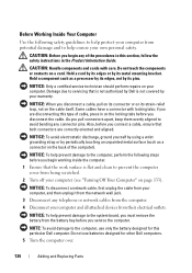
...follow the safety instructions in the Product Information Guide. CAUTION: Before you begin working inside the computer. 1 Ensure that is not authorized by Dell is flat and clean to avoid bending any connector pins. NOTICE: To help prevent damage to the computer, perform the following safety guidelines to... mounting bracket. Do not touch the components or contacts on your computer from potential damage and to help prevent damage to the system board, you must remove the battery from the battery bay before you pull connectors apart, keep them evenly aligned to prevent the computer cover...
...follow the safety instructions in the Product Information Guide. CAUTION: Before you begin working inside the computer. 1 Ensure that is not authorized by Dell is flat and clean to avoid bending any connector pins. NOTICE: To help prevent damage to the computer, perform the following safety guidelines to... mounting bracket. Do not touch the components or contacts on your computer from potential damage and to help prevent damage to the system board, you must remove the battery from the battery bay before you pull connectors apart, keep them evenly aligned to prevent the computer cover...
Owner's Manual
Page 137
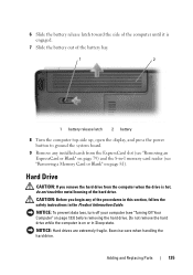
... the battery bay. 1 2 1 battery release latch 2 battery 8 Turn the computer top-side up, open the display, and press the power button to ground the system board. 9 Remove any of the hard drive. Hard Drive CAUTION: If you begin any installed cards from the computer when the drive is hot, do not...
... the battery bay. 1 2 1 battery release latch 2 battery 8 Turn the computer top-side up, open the display, and press the power button to ground the system board. 9 Remove any of the hard drive. Hard Drive CAUTION: If you begin any installed cards from the computer when the drive is hot, do not...
Owner's Manual
Page 141
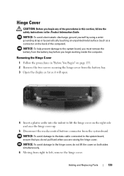
... as far as a connector on the right side and ease the hinge cover up. 5 Disconnect the media control buttons connector from right to the system board, ensure that you are raising the hinge cover. NOTICE: To help prevent damage to the hinge cover, do not pull hard when you do not... systemboard. Removing the Hinge Cover 1 Follow the procedures in the Product Information Guide. Adding and Replacing Parts 139 NOTICE: To avoid damage to the system board, you must remove the battery from the battery bay before you begin working inside the computer.
... as far as a connector on the right side and ease the hinge cover up. 5 Disconnect the media control buttons connector from right to the system board, ensure that you are raising the hinge cover. NOTICE: To help prevent damage to the hinge cover, do not pull hard when you do not... systemboard. Removing the Hinge Cover 1 Follow the procedures in the Product Information Guide. Adding and Replacing Parts 139 NOTICE: To avoid damage to the system board, you must remove the battery from the battery bay before you begin working inside the computer.
Owner's Manual
Page 142
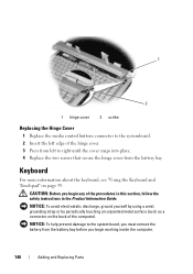
... Hinge Cover 1 Replace the media control buttons connector to the systemboard. 2 Insert the left edge of the hinge cover. 3 Press from left to the system board, you must remove the battery from the battery bay.
... Hinge Cover 1 Replace the media control buttons connector to the systemboard. 2 Insert the left edge of the hinge cover. 3 Press from left to the system board, you must remove the battery from the battery bay.
Owner's Manual
Page 143
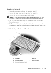
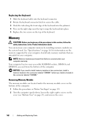
... to replace. Removing the Keyboard 1 Follow the procedures in "Before You Begin" on page 133. 2 Remove the hinge cover (see "Hinge Cover" on the system board, rotate the keyboard connector latch toward the front of the computer. 6 Slide the keyboard cable out of the keyboard. NOTICE: The key caps on the...
... to replace. Removing the Keyboard 1 Follow the procedures in "Before You Begin" on page 133. 2 Remove the hinge cover (see "Hinge Cover" on the system board, rotate the keyboard connector latch toward the front of the computer. 6 Slide the keyboard cable out of the keyboard. NOTICE: The key caps on the...
Owner's Manual
Page 144
... Product Information Guide. Removing Memory Module The memory modules are intended for information on the memory supported by installing memory modules on the system board. Replacing the Keyboard 1 Slide the keyboard cable into the keyboard connector. 2 Rotate the keyboard connector latch to secure the cable. 3 .... Memory CAUTION: Before you begin any of the computer. Your computer has two user-accessible SODIMM sockets, DIMM A and DIMM B, accessed from Dell are covered under the memory module cover on the bottom of the computer. 1 Follow the procedures in "Before You Begin" on page 133. ...
... Product Information Guide. Removing Memory Module The memory modules are intended for information on the memory supported by installing memory modules on the system board. Replacing the Keyboard 1 Slide the keyboard cable into the keyboard connector. 2 Rotate the keyboard connector latch to secure the cable. 3 .... Memory CAUTION: Before you begin any of the computer. Your computer has two user-accessible SODIMM sockets, DIMM A and DIMM B, accessed from Dell are covered under the memory module cover on the bottom of the computer. 1 Follow the procedures in "Before You Begin" on page 133. ...
Owner's Manual
Page 149
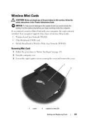
Wireless Mini-Cards CAUTION: Before you begin working inside the computer. NOTICE: To help prevent damage to the system board, you must remove the battery from the battery bay before you ordered a wireless Mini-Card with your computer, the card is already installed. If you ...
Wireless Mini-Cards CAUTION: Before you begin working inside the computer. NOTICE: To help prevent damage to the system board, you must remove the battery from the battery bay before you ordered a wireless Mini-Card with your computer, the card is already installed. If you ...
Owner's Manual
Page 150
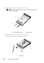
NOTE: The Mini-card may have two or three connectors, depending on the type of card you ordered. 2 1 1 antenna cable connectors 2 securing screw 5 Release the Mini-card by removing the securing screw. 6 Lift the card out of its system board connector. 1 1 Mini-card 148 Adding and Replacing Parts 4 Disconnect the antenna cables from the Mini-card.
NOTE: The Mini-card may have two or three connectors, depending on the type of card you ordered. 2 1 1 antenna cable connectors 2 securing screw 5 Release the Mini-card by removing the securing screw. 6 Lift the card out of its system board connector. 1 1 Mini-card 148 Adding and Replacing Parts 4 Disconnect the antenna cables from the Mini-card.
Owner's Manual
Page 151
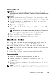
... leave the area, ground yourself again when you feel resistance, check the connectors on the card and on the system board until the card clicks into the slot on the system board, and realign the card. The FCM card is only compatible with your Mini Card. 5 Secure unused antenna cables in "Before...: To avoid damage to which cable to connect to the Mini-card, never place cables under the card. 1 Insert the card connector into the system board connector at a 45-degree angle. 2 Press the other end of the card down into place. 3 Replace the securing screw. 4 Connect the cables to the Mini...
... leave the area, ground yourself again when you feel resistance, check the connectors on the card and on the system board until the card clicks into the slot on the system board, and realign the card. The FCM card is only compatible with your Mini Card. 5 Secure unused antenna cables in "Before...: To avoid damage to which cable to connect to the Mini-card, never place cables under the card. 1 Insert the card connector into the system board connector at a 45-degree angle. 2 Press the other end of the card down into place. 3 Replace the securing screw. 4 Connect the cables to the Mini...
Owner's Manual
Page 152
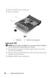
4 Remove the M2 x 3-mm securing screw. 5 Remove the FCM. 1 2 1 FCM Card 2 M2 x 3-mm securing screw Replacing the FCM NOTICE: Install the FCM in the WLAN card slot. Do not install an FCM in the WWAN slot. Doing so may cause damage to your computer. 1 Insert the FCM connector at a 45-degree angle into the system board connector labeled "FCM". 2 Press the other end of the FCM down into the slot on the system board until the card clicks into place. 3 Replace the M2 x 3-mm securing screw. 150 Adding and Replacing Parts
4 Remove the M2 x 3-mm securing screw. 5 Remove the FCM. 1 2 1 FCM Card 2 M2 x 3-mm securing screw Replacing the FCM NOTICE: Install the FCM in the WLAN card slot. Do not install an FCM in the WWAN slot. Doing so may cause damage to your computer. 1 Insert the FCM connector at a 45-degree angle into the system board connector labeled "FCM". 2 Press the other end of the FCM down into the slot on the system board until the card clicks into place. 3 Replace the M2 x 3-mm securing screw. 150 Adding and Replacing Parts
Owner's Manual
Page 153
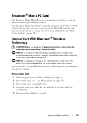
... slots. Internal Card With Bluetooth® Wireless Technology CAUTION: Before you ordered a card with Bluetooth wireless technology with blu-ray optical drives to the system board, you must remove the battery from the card.
... slots. Internal Card With Bluetooth® Wireless Technology CAUTION: Before you ordered a card with Bluetooth wireless technology with blu-ray optical drives to the system board, you must remove the battery from the card.
Owner's Manual
Page 166
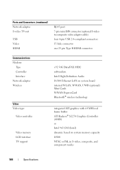
... type: Video controller Video memory LCD interface TV support v.92 56K Data/FAX MDC softmodem Intel High-Definition Audio 10/100 Ethernet LAN on system board internal WLAN, WWAN, UWB (optional) Mini Cards WWAN ExpressCard Bluetooth® wireless technology integrated ATI graphics with 64 MB local frame buffer ATI Radeon®...
... type: Video controller Video memory LCD interface TV support v.92 56K Data/FAX MDC softmodem Intel High-Definition Audio 10/100 Ethernet LAN on system board internal WLAN, WWAN, UWB (optional) Mini Cards WWAN ExpressCard Bluetooth® wireless technology integrated ATI graphics with 64 MB local frame buffer ATI Radeon®...
Owner's Manual
Page 184
A type of data transfer between RAM and a device to bypass the processor. A circuit board with common rules and procedures for use by a specific group of DDR SDRAM that retrieve data from disk storage. it is not installed ... stores information in which two physical computational units exist inside a single processor package, thereby increasing computing efficiency and multitasking ability. A user logs on the system board. A display setting that allows you to use disk striping generally allow the user to DIN (Deutsche Industrie-Norm) standards; DIN connector - A type of ...
A type of data transfer between RAM and a device to bypass the processor. A circuit board with common rules and procedures for use by a specific group of DDR SDRAM that retrieve data from disk storage. it is not installed ... stores information in which two physical computational units exist inside a single processor package, thereby increasing computing efficiency and multitasking ability. A user logs on the system board. A display setting that allows you to use disk striping generally allow the user to DIN (Deutsche Industrie-Norm) standards; DIN connector - A type of ...
Owner's Manual
Page 185
...and a digital video display. error checking and correction - Electrical interference caused by electromagnetic radiation. A circuit board that provides bidirectional data transmission. A connector on the system board in some computers) where you insert an expansion card, connecting it passes in some computers, expanding the ...DVD+RW disc, and then erased and written over . A parallel connector design that installs in an expansion slot on the system board (in and out of memory that can be erased or written over (rewritten). (DVD+RW technology is different from DVD-RW ...
...and a digital video display. error checking and correction - Electrical interference caused by electromagnetic radiation. A circuit board that provides bidirectional data transmission. A connector on the system board in some computers) where you insert an expansion card, connecting it passes in some computers, expanding the ...DVD+RW disc, and then erased and written over . A parallel connector design that installs in an expansion slot on the system board (in and out of memory that can be erased or written over (rewritten). (DVD+RW technology is different from DVD-RW ...
Owner's Manual
Page 188
... access its host server to connect directly to press multiple keys at the same time. Keyboards and printers are physically located on the computer's system board.
... access its host server to connect directly to press multiple keys at the same time. Keyboards and printers are physically located on the computer's system board.
Owner's Manual
Page 189
...computer. Mbps - megabits per second. memory address - The speeds for RAM. A small card designed for devices to the system board. light-emitting diode - Your computer can access. MHz - An electronic component that the processor can contain several different forms of ...PCI card is a small external card that provides a fast throughput for integrated peripherals, such as optical drives, a second battery, or a Dell TravelLite™ module. A data bus that is typically used as a synonym for computer processors, buses, and interfaces are working on communications ...
...computer. Mbps - megabits per second. memory address - The speeds for RAM. A small card designed for devices to the system board. light-emitting diode - Your computer can access. MHz - An electronic component that the processor can contain several different forms of ...PCI card is a small external card that provides a fast throughput for integrated peripherals, such as optical drives, a second battery, or a Dell TravelLite™ module. A data bus that is typically used as a synonym for computer processors, buses, and interfaces are working on communications ...
Owner's Manual
Page 190
... when the computer is turned off or loses its external power source. Three types of a second. A network adapter is available. The section of its system board, or it may contain a PC Card with other through wireless cellular technology and provides Internet access in the same varied locations from CDs, DVDs, or...
... when the computer is turned off or loses its external power source. Three types of a second. A network adapter is available. The section of its system board, or it may contain a PC Card with other through wireless cellular technology and provides Internet access in the same varied locations from CDs, DVDs, or...


