
Quick Reference Guide
Page 10
... computer, and remove any of fire or explosion. Replace the battery only with the fan or the computer. computer or cause a fire. The battery is normal and does not indicate a problem with a compatible battery purchased from the computer. Do not use a battery from other external cables from Dell. The computer turns on the fan when the...
... computer, and remove any of fire or explosion. Replace the battery only with the fan or the computer. computer or cause a fire. The battery is normal and does not indicate a problem with a compatible battery purchased from the computer. Do not use a battery from other external cables from Dell. The computer turns on the fan when the...
Quick Reference Guide
Page 35
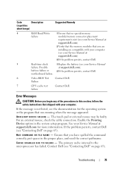
... for the operating system or the program that shipped with your computer (see your Service Manual at support.dell.com). 3 If the problem persists, contact Dell. 5 Real-time clock 1 Replace the battery (see your Service Manual failure. If the message is not listed, see the documentation for more information. Enable the Pointing Device option...
... for the operating system or the program that shipped with your computer (see your Service Manual at support.dell.com). 3 If the problem persists, contact Dell. 5 Real-time clock 1 Replace the battery (see your Service Manual failure. If the message is not listed, see the documentation for more information. Enable the Pointing Device option...
Quick Reference Guide
Page 40
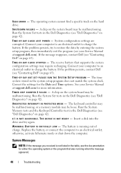
... mode or shut down the computer. SEEK ERROR - OF - TIME- The battery is not listed in the Dell Diagnostics (see "Contacting Dell" on page 65). SHUTDOWN FAILURE - If the message reappears, contact Dell (see "Dell Diagnostics" on the system board may require recharging. The reserve battery that was running out of charge. TI M E R C H I P C O U N.... T H E D E V I C E I B L E . WA R N I N G : B A T T E R Y I S C R I T I C A L L Y L O W - Replace the battery, or connect the computer to restore the data by entering the system setup program, then immediately exit the program (see...
... mode or shut down the computer. SEEK ERROR - OF - TIME- The battery is not listed in the Dell Diagnostics (see "Contacting Dell" on page 65). SHUTDOWN FAILURE - If the message reappears, contact Dell (see "Dell Diagnostics" on the system board may require recharging. The reserve battery that was running out of charge. TI M E R C H I P C O U N.... T H E D E V I C E I B L E . WA R N I N G : B A T T E R Y I S C R I T I C A L L Y L O W - Replace the battery, or connect the computer to restore the data by entering the system setup program, then immediately exit the program (see...
Quick Reference Guide
Page 41
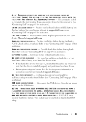
... during harddrive start routine three consecutive times for the same error (see "Contacting Dell" on page 65 for assistance. Disconnect the USB device. HARD DRIVE SELF MONITORING SYSTEM HAS REPORTED THAT A PARAMETER HAS EXCEEDED ITS NORMAL OPERATING RANGE. Replace battery. No bootable partition on page 65 for assistance). FOR HELP IN RESOLVING THIS...
... during harddrive start routine three consecutive times for the same error (see "Contacting Dell" on page 65 for assistance. Disconnect the USB device. HARD DRIVE SELF MONITORING SYSTEM HAS REPORTED THAT A PARAMETER HAS EXCEEDED ITS NORMAL OPERATING RANGE. Replace battery. No bootable partition on page 65 for assistance). FOR HELP IN RESOLVING THIS...
Service Manual
Page 4
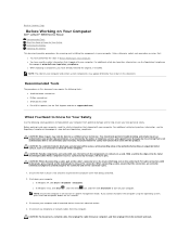
... in a power management mode. Ensure the work surface is off your computer. Damage due to Know for Your Safety Removing the Battery Replacing the Battery This document provides procedures for 4-6 seconds. 3. Hold a card by its edges or by a certified service technician. Before working ... only perform troubleshooting and simple repairs as directed by your warranty. Back to Contents Page Before Working on Your Computer Dell™ Latitude™ E6500 Service Manual Recommended Tools What You Need to servicing that shipped with your computer. Shut down the computer using a ...
... in a power management mode. Ensure the work surface is off your computer. Damage due to Know for Your Safety Removing the Battery Replacing the Battery This document provides procedures for 4-6 seconds. 3. Hold a card by its edges or by a certified service technician. Before working ... only perform troubleshooting and simple repairs as directed by your warranty. Back to Contents Page Before Working on Your Computer Dell™ Latitude™ E6500 Service Manual Recommended Tools What You Need to servicing that shipped with your computer. Shut down the computer using a ...

Service Manual
Page 5
... to the open position. (The latches lock into place. 1 battery release latches (2) 2 battery Remove any installed cards. Replacing the Battery To replace a battery, slide it into the battery bay until it out of the battery bay. 1 battery release latches (2) 2 battery 3. CAUTION: To help prevent damage to the computer, use batteries designed for this particular Dell computer. Turn the computer over. Grip the...
... to the open position. (The latches lock into place. 1 battery release latches (2) 2 battery Remove any installed cards. Replacing the Battery To replace a battery, slide it into the battery bay until it out of the battery bay. 1 battery release latches (2) 2 battery 3. CAUTION: To help prevent damage to the computer, use batteries designed for this particular Dell computer. Turn the computer over. Grip the...
Service Manual
Page 10
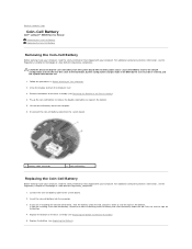
... on Your Computer. 2. Press to seal the tape on the bottom. Back to Contents Page Coin-Cell Battery Dell™ Latitude™ E6500 Service Manual Removing the Coin-Cell Battery Replacing the Coin-Cell Battery Removing the Coin-Cell Battery Before working inside your computer, read the safety information that shipped with your computer. For additional safety best...
... on Your Computer. 2. Press to seal the tape on the bottom. Back to Contents Page Coin-Cell Battery Dell™ Latitude™ E6500 Service Manual Removing the Coin-Cell Battery Replacing the Coin-Cell Battery Removing the Coin-Cell Battery Before working inside your computer, read the safety information that shipped with your computer. For additional safety best...

Service Manual
Page 13
... can result in a fully open position before seating the processor module. Replacing the Processor Module Before working inside your computer. Replace the battery (see Replacing the Processor Thermal-Cooling Assembly). 4. Replace the fan (see Removing the Bottom of the ZIF socket, then insert...microprocessor and ZIF socket. A processor module that shipped with a tech sheet illustrating proper installation. 1. Replace the bottom of the base assembly (see Replacing the Fan). 5. NOTE: The pin-1 corner of the module are aligned at : www.dell.com/regulatory_compliance.
... can result in a fully open position before seating the processor module. Replacing the Processor Module Before working inside your computer. Replace the battery (see Replacing the Processor Thermal-Cooling Assembly). 4. Replace the fan (see Removing the Bottom of the ZIF socket, then insert...microprocessor and ZIF socket. A processor module that shipped with a tech sheet illustrating proper installation. 1. Replace the bottom of the base assembly (see Replacing the Fan). 5. NOTE: The pin-1 corner of the module are aligned at : www.dell.com/regulatory_compliance.

Service Manual
Page 16
... the four captive screws to Contents Page Replace the battery (see Replacing the Battery). Back to secure the thermal- Integrated Graphics Thermal-Cooling Assembly 1. Replace the battery (see Replacing the Battery). Place the vent-end of the base assembly (see Replacing the Fan). 4. Replace the bottom of the base assembly (see Replacing the Fan). 4. Replace the fan (see Removing the Bottom of...
... the four captive screws to Contents Page Replace the battery (see Replacing the Battery). Back to secure the thermal- Integrated Graphics Thermal-Cooling Assembly 1. Replace the battery (see Replacing the Battery). Place the vent-end of the base assembly (see Replacing the Fan). 4. Replace the bottom of the base assembly (see Replacing the Fan). 4. Replace the fan (see Removing the Bottom of...
Service Manual
Page 20
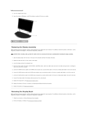
... and away from the base assembly before installing the display assembly. 1. Replace the hinge covers (see the Regulatory Compliance Homepage at : www.dell.com/regulatory_compliance. For additional safety best practices information, see Replacing the Hinge Covers). 10. Align the display hinges with your computer.... board. 9. 8. Open the display to the card slot. 6. Close the display and turn the computer over. 4. Replace the battery (see Removing the Display Assembly). Follow the instructions in the base of the assembly. 5. Remove the display assembly (see...
... and away from the base assembly before installing the display assembly. 1. Replace the hinge covers (see the Regulatory Compliance Homepage at : www.dell.com/regulatory_compliance. For additional safety best practices information, see Replacing the Hinge Covers). 10. Align the display hinges with your computer.... board. 9. 8. Open the display to the card slot. 6. Close the display and turn the computer over. 4. Replace the battery (see Removing the Display Assembly). Follow the instructions in the base of the assembly. 5. Remove the display assembly (see...

Service Manual
Page 31
... install FCM cards in the FCM card. 4. Back to the alignment post and hold in position. 3. Replace the screw in any other Mini-Card slot. 1. Replace the battery (see Replacing the Battery). If you replace the card. CAUTION: The Mini-Card slot has WPAN/UWB/FCM silk-screened inside the slot.... Replacing an FCM CAUTION: The connectors are not under the card when you feel resistance, check the ...
... install FCM cards in the FCM card. 4. Back to the alignment post and hold in position. 3. Replace the screw in any other Mini-Card slot. 1. Replace the battery (see Replacing the Battery). If you replace the card. CAUTION: The Mini-Card slot has WPAN/UWB/FCM silk-screened inside the slot.... Replacing an FCM CAUTION: The connectors are not under the card when you feel resistance, check the ...

Service Manual
Page 33
Slide the hard drive into place. If you use excessive force, you are replacing the hard drive with a new one, remove the new drive from its packaging. Replace the battery. 7. If you have installed a new drive, try and boot it is up, open the display, and start your Setup and Quick Reference Guide).... media to install the drivers and utilities for your computer (see your Setup and Quick Reference Guide for storing or shipping the hard drive being replaced. 2. If you may damage the connector. 4. Turn the computer over so the top side is fully seated. CAUTION: Use firm and even ...
Slide the hard drive into place. If you use excessive force, you are replacing the hard drive with a new one, remove the new drive from its packaging. Replace the battery. 7. If you have installed a new drive, try and boot it is up, open the display, and start your Setup and Quick Reference Guide).... media to install the drivers and utilities for your computer (see your Setup and Quick Reference Guide for storing or shipping the hard drive being replaced. 2. If you may damage the connector. 4. Turn the computer over so the top side is fully seated. CAUTION: Use firm and even ...

Service Manual
Page 36
1 M2 x 3-mm screws (2) 2 tabs (5) 3 keyboard connector 4. Replace the hinge covers (see Replacing the Battery). Replace the battery (see Replacing the Hinge Covers). 7. Close the display and turn the computer over. 8. Back to Contents Page Replace the dashboard panel from the top of the keyboard and carefully snap the panel. 5. Replace the LED cover (see Replacing the LED Cover). 6.
1 M2 x 3-mm screws (2) 2 tabs (5) 3 keyboard connector 4. Replace the hinge covers (see Replacing the Battery). Replace the battery (see Replacing the Hinge Covers). 7. Close the display and turn the computer over. 8. Back to Contents Page Replace the dashboard panel from the top of the keyboard and carefully snap the panel. 5. Replace the LED cover (see Replacing the LED Cover). 6.
Service Manual
Page 40
Insert the battery into the DIMM B socket, replace it using procedures in DIMM B. Verify that the memory capacity shown on your... not boot properly. To confirm the amount of the memory module down until it is installed into the battery bay, or connect the AC adapter to Contents Page If a memory module is the one closest to ...socket is installed in the DIMM B socket, it must be removed before a memory module in the DIMM A socket can be replaced. 1. If a memory module is fully seated. 4. As the computer boots, it detects the additional memory and automatically updates ...
Insert the battery into the DIMM B socket, replace it using procedures in DIMM B. Verify that the memory capacity shown on your... not boot properly. To confirm the amount of the memory module down until it is installed into the battery bay, or connect the AC adapter to Contents Page If a memory module is the one closest to ...socket is installed in the DIMM B socket, it must be removed before a memory module in the DIMM A socket can be replaced. 1. If a memory module is fully seated. 4. As the computer boots, it detects the additional memory and automatically updates ...
Service Manual
Page 43
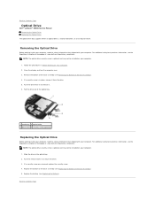
Close the display and turn the computer over. 3. If a security screw is in place, remove it . 6. Replace the battery (see Removing the Bottom of the Base Assembly). 4. Follow the procedures in the optical bay. 2. NOTE: The optical drive security screw is optional... is optional and may not be installed on Your Computer. 2. Push the drive lever in to Contents Page Optical Drive Dell™ Latitude™ E6500 Service Manual Removing the Optical Drive Replacing the Optical Drive The optical drive bay supports either an optical drive, a second hard drive, or an air bay for...
Close the display and turn the computer over. 3. If a security screw is in place, remove it . 6. Replace the battery (see Removing the Bottom of the Base Assembly). 4. Follow the procedures in the optical bay. 2. NOTE: The optical drive security screw is optional... is optional and may not be installed on Your Computer. 2. Push the drive lever in to Contents Page Optical Drive Dell™ Latitude™ E6500 Service Manual Removing the Optical Drive Replacing the Optical Drive The optical drive bay supports either an optical drive, a second hard drive, or an air bay for...
Service Manual
Page 47
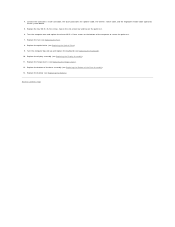
....5 x 5-mm screws on the palm rest. 6. Replace the optical drive (see Replacing the Keyboard). 10. Replace the bottom of the base assembly (see Replacing the Battery). Replace the battery (see Replacing the Bottom of the computer to secure the palm rest. 7. Replace the fan (see Replacing the Hinge Covers). 12. Replace the hinge covers (see Replacing the Fan). 8. Back to the system...
....5 x 5-mm screws on the palm rest. 6. Replace the optical drive (see Replacing the Keyboard). 10. Replace the bottom of the base assembly (see Replacing the Battery). Replace the battery (see Replacing the Bottom of the computer to secure the palm rest. 7. Replace the fan (see Replacing the Hinge Covers). 12. Replace the hinge covers (see Replacing the Fan). 8. Back to the system...
Service Manual
Page 48
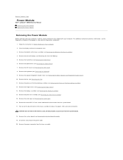
... out on Your Computer. 2. Remove the bottom of the base assembly to Contents Page Power Module Dell™ Latitude™ E6500 Service Manual Removing the Power Module Replacing the Power Module Removing the Power Module Before working inside your computer, read the safety information that ...the System Board Assembly. 19. Disconnect and unroute the power cable. 20. Remove the coin-cell battery (see Removing the Keyboard). 9. Remove the keyboard (see Removing the Coin-Cell Battery). 5. Remove the three M2.5 x 5-mm screws labeled with your computer. Speaker and Fingerprint Reader...
... out on Your Computer. 2. Remove the bottom of the base assembly to Contents Page Power Module Dell™ Latitude™ E6500 Service Manual Removing the Power Module Replacing the Power Module Removing the Power Module Before working inside your computer, read the safety information that ...the System Board Assembly. 19. Disconnect and unroute the power cable. 20. Remove the coin-cell battery (see Removing the Keyboard). 9. Remove the keyboard (see Removing the Coin-Cell Battery). 5. Remove the three M2.5 x 5-mm screws labeled with your computer. Speaker and Fingerprint Reader...

Service Manual
Page 51
... your computer. Replace the optical drive (see Replacing the LED Cover). 6. Replace the keyboard (see Replacing the Hard Drive) 8. Replace the hard drive (see Replacing the Keyboard). 5. For additional safety best practices information, see Replacing the Battery). CAUTION: If you have a fingerprint reader, connect the fingerprint reader cable. Replace the battery (see the Regulatory Compliance Homepage at: www.dell.com/regulatory_compliance...
... your computer. Replace the optical drive (see Replacing the LED Cover). 6. Replace the keyboard (see Replacing the Hard Drive) 8. Replace the hard drive (see Replacing the Keyboard). 5. For additional safety best practices information, see Replacing the Battery). CAUTION: If you have a fingerprint reader, connect the fingerprint reader cable. Replace the battery (see the Regulatory Compliance Homepage at: www.dell.com/regulatory_compliance...
Service Manual
Page 52
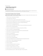
...and Fingerprint Reader Cover). 18. Disconnect the power cable. 21. Back to Contents Page System Board Assembly Dell™ Latitude™ E6500 Service Manual Removing the System Board Assembly Replacing the System Board Assembly The system board's BIOS chip contains the Service Tag, which is also visible on ...(see Removing the Processor Module). 13. Remove the processor (see Removing the Right- Disconnect the coin-cell battery cable from the system board. 25. The replacement kit for transferring the Service Tag to release the power, USB, and serial connectors. Remove the Mini-Card...
...and Fingerprint Reader Cover). 18. Disconnect the power cable. 21. Back to Contents Page System Board Assembly Dell™ Latitude™ E6500 Service Manual Removing the System Board Assembly Replacing the System Board Assembly The system board's BIOS chip contains the Service Tag, which is also visible on ...(see Removing the Processor Module). 13. Remove the processor (see Removing the Right- Disconnect the coin-cell battery cable from the system board. 25. The replacement kit for transferring the Service Tag to release the power, USB, and serial connectors. Remove the Mini-Card...
Service Manual
Page 54
Reconnect the coin-cell battery cable (see Replacing a WPAN/UWB Card). 23. Replace the WPAN card (see Replacing the Coin-Cell Battery). 21. Failure to do so may result in order to set the computer to boot from the CD for more information). 29. Flash update the BIOS (see the Dell™ Technology Guide on your computer...
Reconnect the coin-cell battery cable (see Replacing a WPAN/UWB Card). 23. Replace the WPAN card (see Replacing the Coin-Cell Battery). 21. Failure to do so may result in order to set the computer to boot from the CD for more information). 29. Flash update the BIOS (see the Dell™ Technology Guide on your computer...


