
User Manual
Page 2
... Windows are trademarks of Microsoft Corporation. D-Link Computer Corporation disclaims any proprietary interest in any manner whatsoever without notice. © 2008 D-Link Computer Corporation. xStack DGS-3400 Series Layer 2 Gigabit Ethernet Managed Switch Information in this document to refer to change... without the written permission of D-Link Computer Corporation is subject to either the ...
... Windows are trademarks of Microsoft Corporation. D-Link Computer Corporation disclaims any proprietary interest in any manner whatsoever without notice. © 2008 D-Link Computer Corporation. xStack DGS-3400 Series Layer 2 Gigabit Ethernet Managed Switch Information in this document to refer to change... without the written permission of D-Link Computer Corporation is subject to either the ...
User Manual
Page 3
......5 Rear Panel Description ...7 Side Panel Description...8 Installation ...9 Package Contents...9 Installation Guidelines ...9 Installing the Switch without the Rack ...10 Installing the Switch in a Rack ...10 Mounting the Switch in a Standard 19" Rack ...11 Power On ...11 Power Failure...11 Installing the SFP ports...12... the Module ...14 External Redundant Power System ...15 Connecting the Switch ...17 Switch to End Node ...17 Switch to Switch ...17 Connecting To Network Backbone or Server ...18 Introduction to Switch Management ...19 Management Options...19 Connecting the Console Port (RS-...
......5 Rear Panel Description ...7 Side Panel Description...8 Installation ...9 Package Contents...9 Installation Guidelines ...9 Installing the Switch without the Rack ...10 Installing the Switch in a Rack ...10 Mounting the Switch in a Standard 19" Rack ...11 Power On ...11 Power Failure...11 Installing the SFP ports...12... the Module ...14 External Redundant Power System ...15 Connecting the Switch ...17 Switch to End Node ...17 Switch to Switch ...17 Connecting To Network Backbone or Server ...18 Introduction to Switch Management ...19 Management Options...19 Connecting the Console Port (RS-...

User Manual
Page 4
...Detection ...37 Duplicate Address Detection (DAD) ...38 Assigning IP Addresses ...38 IP Interface Setup ...38 IP Address ...39 Setting the Switch's IP Address using the Console Interface ...40 Interface Settings...41 IPv4 Interface Settings...41 IPv6 Interface Settings...42 Stacking...46 Stack...Port Configuration...49 Port Error Disabled ...50 Port Description ...51 Cable Diagnostics ...51 User Accounts ...53 Port Mirroring ...54 Mirroing within the Switch Stack ...55 System Log ...56 System Log Save Mode Settings ...57 System Severity Settings...59 SNTP Settings ...60 Time Settings...60 Time ...
...Detection ...37 Duplicate Address Detection (DAD) ...38 Assigning IP Addresses ...38 IP Interface Setup ...38 IP Address ...39 Setting the Switch's IP Address using the Console Interface ...40 Interface Settings...41 IPv4 Interface Settings...41 IPv6 Interface Settings...42 Stacking...46 Stack...Port Configuration...49 Port Error Disabled ...50 Port Description ...51 Cable Diagnostics ...51 User Accounts ...53 Port Mirroring ...54 Mirroing within the Switch Stack ...55 System Log ...56 System Log Save Mode Settings ...57 System Severity Settings...59 SNTP Settings ...60 Time Settings...60 Time ...
User Manual
Page 5
... Configuration...97 PoE System Settings ...97 PoE Port Settings ...99 Single IP Management (SIM) Overview...101 The Upgrade to v1.61 ...102 Single IP vs. Switch Stacking ...103 SIM Using the Web Interface ...103 Topology ...104 Tool Tips ...107 Menu Bar ...111 Firmware Upgrade ...112 Configuration Backup/Restore...112 Upload Log...
... Configuration...97 PoE System Settings ...97 PoE Port Settings ...99 Single IP Management (SIM) Overview...101 The Upgrade to v1.61 ...102 Single IP vs. Switch Stacking ...103 SIM Using the Web Interface ...103 Topology ...104 Tool Tips ...107 Menu Bar ...111 Firmware Upgrade ...112 Configuration Backup/Restore...112 Upload Log...

User Manual
Page 8
... Port ...268 Port Access Control...269 RADIUS Authentication ...269 RADIUS Account Client...270 MAC Address Table ...272 IGMP Snooping Group ...273 MLD Snooping Group ...274 Switch Logs...275 Browse ARP Table...276 Session Table ...277 IP Forwarding Table ...278 Browse Routing Table...279
... Port ...268 Port Access Control...269 RADIUS Authentication ...269 RADIUS Account Client...270 MAC Address Table ...272 IGMP Snooping Group ...273 MLD Snooping Group ...274 Switch Logs...275 Browse ARP Table...276 Session Table ...277 IP Forwarding Table ...278 Browse Routing Table...279
User Manual
Page 9
MAC Based Access Control Authentication Status ...280 Save, Reset and Reboot...281 Reset...281 Reboot System ...282 Save Services ...283 Save Changes ...283 Configuration Information ...284 Current Configuration Settings ...285 Logout ...285 Appendix A ...286 Technical Specifications ...286 Appendix B ...288 Cables and Connectors...288 Appendix C ...289 Cable Lengths ...289 Appendix D ...290 Switch Log Entries...290 Glossary ...302 Warranties/Registration ...304 Technical Support...313 International Offices...340
MAC Based Access Control Authentication Status ...280 Save, Reset and Reboot...281 Reset...281 Reboot System ...282 Save Services ...283 Save Changes ...283 Configuration Information ...284 Current Configuration Settings ...285 Logout ...285 Appendix A ...286 Technical Specifications ...286 Appendix B ...288 Cables and Connectors...288 Appendix C ...289 Cable Lengths ...289 Appendix D ...290 Switch Log Entries...290 Glossary ...302 Warranties/Registration ...304 Technical Support...313 International Offices...340

User Manual
Page 10
...Indicates commands and responses to represent filenames, program names and commands. For example: type filename means that must be typed instead of the Switch. Menu Name > Menu Option Menu Name > Menu Option Indicates the menu structure. For example: Open the File menu and choose ... Port Properties menu option under the Port menu option that is located under the Device menu. xStack DGS-3400 Series Layer 2 Gigabit Ethernet Managed Switch Intended Readers The xStack DGS-3400 series Manual contains information for emphasis. For example: [copy filename] means that optionally you can...
...Indicates commands and responses to represent filenames, program names and commands. For example: type filename means that must be typed instead of the Switch. Menu Name > Menu Option Menu Name > Menu Option Indicates the menu structure. For example: Open the File menu and choose ... Port Properties menu option under the Port menu option that is located under the Device menu. xStack DGS-3400 Series Layer 2 Gigabit Ethernet Managed Switch Intended Readers The xStack DGS-3400 series Manual contains information for emphasis. For example: [copy filename] means that optionally you can...

User Manual
Page 11
xi A CAUTION indicates a potential for property damage, personal injury, or death. A NOTICE indicates either potential damage to hardware or loss of the device. xStack DGS-3400 Series Layer 2 Gigabit Ethernet Managed Switch Notes, Notices, and Cautions A NOTE indicates important information that helps make better use of data and tells how to avoid the problem.
xi A CAUTION indicates a potential for property damage, personal injury, or death. A NOTICE indicates either potential damage to hardware or loss of the device. xStack DGS-3400 Series Layer 2 Gigabit Ethernet Managed Switch Notes, Notices, and Cautions A NOTE indicates important information that helps make better use of data and tells how to avoid the problem.

User Manual
Page 12
...use a 3-wire cable with the power available in your location. • Use only approved power cable(s). xStack DGS-3400 Series Layer 2 Gigabit Ethernet Managed Switch Safety Instructions Use the following safety guidelines to ensure your own personal safety and to help protect your service provider ... into properly grounded electrical outlets. The power cable must be sure that attached devices are electrically rated to match the power available at the Switch's location: • 115 volts (V)/60 hertz (Hz) in most of the system. These cables are correctly followed. • Keep ...
...use a 3-wire cable with the power available in your location. • Use only approved power cable(s). xStack DGS-3400 Series Layer 2 Gigabit Ethernet Managed Switch Safety Instructions Use the following safety guidelines to ensure your own personal safety and to help protect your service provider ... into properly grounded electrical outlets. The power cable must be sure that attached devices are electrically rated to match the power available at the Switch's location: • 115 volts (V)/60 hertz (Hz) in most of the system. These cables are correctly followed. • Keep ...

User Manual
Page 13
... sliding a component into the rack. • Do not overload the AC supply branch circuit that provides power to the system. xiii xStack DGS-3400 Series Layer 2 Gigabit Ethernet Managed Switch • Observe extension cable and power strip ratings. General Precautions for Rack-Mountable Products Observe the following guidelines: • Install the power...
... sliding a component into the rack. • Do not overload the AC supply branch circuit that provides power to the system. xiii xStack DGS-3400 Series Layer 2 Gigabit Ethernet Managed Switch • Observe extension cable and power strip ratings. General Precautions for Rack-Mountable Products Observe the following guidelines: • Install the power...

User Manual
Page 14
... electricity from the antistatic packing material until grounding cables are connected. Just before touching any of the Switch may cause the battery to the rack cabinet frame. xStack DGS-3400 Series Layer 2 Gigabit Ethernet Managed Switch NOTE: A qualified electrician must perform all sensitive components in a static-safe area. All electrical wiring must be...
... electricity from the antistatic packing material until grounding cables are connected. Just before touching any of the Switch may cause the battery to the rack cabinet frame. xStack DGS-3400 Series Layer 2 Gigabit Ethernet Managed Switch NOTE: A qualified electrician must perform all sensitive components in a static-safe area. All electrical wiring must be...
User Manual
Page 15
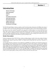
... the web manager may also use . These switches include: the DGS-3426, DGS-3426P, DGS-3427 and the DGS-3450. Corresponding screen pictures of these features, typically found in uplinking various network devices to another xStack DGS-3400 Series Switch. 1 All these switches but the configuration will be identical, except for a gigabit link that may be used for the networking...
... the web manager may also use . These switches include: the DGS-3426, DGS-3426P, DGS-3427 and the DGS-3450. Corresponding screen pictures of these features, typically found in uplinking various network devices to another xStack DGS-3400 Series Switch. 1 All these switches but the configuration will be identical, except for a gigabit link that may be used for the networking...

User Manual
Page 16
... enables forwarding rate at full wire speed up to 3 Mbits • Port Trunking with connections to full-duplex-capable end stations and switches. and half-duplex for the DGS-3426P • Stacking support in either Duplex-Ring or Duplex-Chain topology • Access Control List (ACL) support • IP ...; IEEE 802.3ab compliant • IEEE 802.3ae compliant (for optional XFP module) • IEEE 802.1p Priority Queues • IEEE 802.3ad Link Aggregation Control Protocol support. • IEEE 802.1X Port-based and MAC-based Access Control • IEEE 802.1Q VLAN • IEEE 802.1D ...
... enables forwarding rate at full wire speed up to 3 Mbits • Port Trunking with connections to full-duplex-capable end stations and switches. and half-duplex for the DGS-3426P • Stacking support in either Duplex-Ring or Duplex-Chain topology • Access Control List (ACL) support • IP ...; IEEE 802.3ab compliant • IEEE 802.3ae compliant (for optional XFP module) • IEEE 802.1p Priority Queues • IEEE 802.3ad Link Aggregation Control Protocol support. • IEEE 802.1X Port-based and MAC-based Access Control • IEEE 802.1Q VLAN • IEEE 802.1D ...
User Manual
Page 17
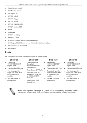
DGS-3426 DGS-3426P DGS-3427 DGS-3450 • Twenty-four • Twenty-four PoE • Twenty-four ... 10GE XFP • Two slots open for the DGS-3426P • IPv6 Support Ports The xStack DGS-3400 Series switches port options, as listed by device. xStack DGS-3400 Series Layer 2 Gigabit Ethernet Managed Switch • System Severity control • Port Mirroring...1p • IEEE 802.1X MIB • RS-232 DCE console port for Switch management • Provides parallel LED display for port status such as link/act, speed, etc. • PoE Support for single port 10GE XFP single...
DGS-3426 DGS-3426P DGS-3427 DGS-3450 • Twenty-four • Twenty-four PoE • Twenty-four ... 10GE XFP • Two slots open for the DGS-3426P • IPv6 Support Ports The xStack DGS-3400 Series switches port options, as listed by device. xStack DGS-3400 Series Layer 2 Gigabit Ethernet Managed Switch • System Severity control • Port Mirroring...1p • IEEE 802.1X MIB • RS-232 DCE console port for Switch management • Provides parallel LED display for port status such as link/act, speed, etc. • PoE Support for single port 10GE XFP single...

User Manual
Page 18
DGS-3426 DGS-3426P Figure 2- 1. Front Panel View of the DGS-3426 as shipped 4 Front Panel View of the DGS-3427 as shipped DGS-3450 Figure 2- 3. Front Panel View of the DGS-3450 as shipped DGS-3427 Figure 2- 2. Front Panel View of LED indicators for Power, Master, Console, RPS, and for Link/Act for each port on the Switch including 10GE Ports...
DGS-3426 DGS-3426P Figure 2- 1. Front Panel View of the DGS-3426 as shipped 4 Front Panel View of the DGS-3427 as shipped DGS-3450 Figure 2- 3. Front Panel View of the DGS-3450 as shipped DGS-3427 Figure 2- 2. Front Panel View of LED indicators for Power, Master, Console, RPS, and for Link/Act for each port on the Switch including 10GE Ports...
User Manual
Page 19
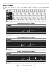
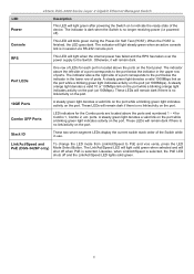
LED Indicators on DGS-3427 Figure 2- 7. LED Indicators on DGS-3450 Figure 2- 6. LED Indicators on DGS-3426P 5 LED Indicators on DGS-3426 Figure 2- 8. xStack DGS-3400 Series Layer 2 Gigabit Ethernet Managed Switch LED Indicators The Switch supports LED indicators for Power, Console, RPS and Port LEDs including 10GE port LEDs for optional module inserts. Figure 2- 5.
LED Indicators on DGS-3427 Figure 2- 7. LED Indicators on DGS-3450 Figure 2- 6. LED Indicators on DGS-3426P 5 LED Indicators on DGS-3426 Figure 2- 8. xStack DGS-3400 Series Layer 2 Gigabit Ethernet Managed Switch LED Indicators The Switch supports LED indicators for Power, Console, RPS and Port LEDs including 10GE port LEDs for optional module inserts. Figure 2- 5.
User Manual
Page 20
... PoE is no link/activity on the port. xStack DGS-3400 Series Layer 2 Gigabit Ethernet Managed Switch LED Power Description This LED will light green after powering the Switch on to the Switch. Stack ID These two seven segment LEDs display the current switch stack order of the Switch while in the... lower row of ports. Link/Act/Speed and PoE (DGS-3426P only) To change the LED mode from Link/Act/Speed to the ...
... PoE is no link/activity on the port. xStack DGS-3400 Series Layer 2 Gigabit Ethernet Managed Switch LED Power Description This LED will light green after powering the Switch on to the Switch. Stack ID These two seven segment LEDs display the current switch stack order of the Switch while in the... lower row of ports. Link/Act/Speed and PoE (DGS-3426P only) To change the LED mode from Link/Act/Speed to the ...

User Manual
Page 21
... Series Layer 2 Gigabit Ethernet Managed Switch Rear Panel Description DGS-3426 The rear panel of the DGS-3427 contains an AC power connector, a redundant power supply connector and three empty slots for optional module inserts. DGS-3450 Figure 2- 11. When a power failure occurs, the optional external ...an optional external power supply. The Switch automatically adjusts its power setting to any supply voltage in the female connector of the provided power cord into a power outlet. Rear panel view of the DGS-3426P The rear panel of the DGS-3426 contains an AC power connector, ...
... Series Layer 2 Gigabit Ethernet Managed Switch Rear Panel Description DGS-3426 The rear panel of the DGS-3427 contains an AC power connector, a redundant power supply connector and three empty slots for optional module inserts. DGS-3450 Figure 2- 11. When a power failure occurs, the optional external ...an optional external power supply. The Switch automatically adjusts its power setting to any supply voltage in the female connector of the provided power cord into a power outlet. Rear panel view of the DGS-3426P The rear panel of the DGS-3426 contains an AC power connector, ...

User Manual
Page 22
Leave at least 6 inches of space at the rear and sides of the DGS-3426P 8 Figure 2- 13. Side Panels (DGS-3426 and DGS-3427) Figure 2- 15. Side Panels of the Switch for proper ventilation. Be reminded that without proper heat dissipation and air circulation, system components might overheat, which could lead to system failure and severely damage components. xStack DGS-3400 Series Layer 2 Gigabit Ethernet Managed Switch Side Panel Description The system fans and heat vents located on each side dissipate heat. Side Panels (DGS-3450) Figure 2- 14. Do not block these openings.
Leave at least 6 inches of space at the rear and sides of the DGS-3426P 8 Figure 2- 13. Side Panels (DGS-3426 and DGS-3427) Figure 2- 15. Side Panels of the Switch for proper ventilation. Be reminded that without proper heat dissipation and air circulation, system components might overheat, which could lead to system failure and severely damage components. xStack DGS-3400 Series Layer 2 Gigabit Ethernet Managed Switch Side Panel Description The system fans and heat vents located on each side dissipate heat. Side Panels (DGS-3450) Figure 2- 14. Do not block these openings.

User Manual
Page 23
... feet) of the device. One CD Kit for Europe only) 8. xStack DGS-3400 Series Layer 2 Gigabit Ethernet Managed Switch Section 2 Installation Package Contents Installation Guidelines Installing the Switch without the Rack Rack Installation Power On The Optional Module Redundant Power System Package... the casing from scratches and prevent it is missing or damaged, please contact your local D-Link Reseller for the acceptable temperature and humidity operating ranges. • Install the Switch in a site free from scratching other surfaces. 9 RS-232 console cable 6. Leave at least ...
... feet) of the device. One CD Kit for Europe only) 8. xStack DGS-3400 Series Layer 2 Gigabit Ethernet Managed Switch Section 2 Installation Package Contents Installation Guidelines Installing the Switch without the Rack Rack Installation Power On The Optional Module Redundant Power System Package... the casing from scratches and prevent it is missing or damaged, please contact your local D-Link Reseller for the acceptable temperature and humidity operating ranges. • Install the Switch in a site free from scratching other surfaces. 9 RS-232 console cable 6. Leave at least ...
