
User Manual
Page 2
...this document to refer to change without the written permission of Microsoft Corporation. Microsoft and Windows are trademarks of D-Link Computer Corporation; Other trademarks and trade names may be used in trademarks and trade names other than its own.... D-Link and the D-LINK logo are registered trademarks of D-Link Computer Corporation is subject to either the entities claiming the marks and names or their products. August 2008 P/N 651GS3400065G ii D-Link Computer Corporation disclaims any manner whatsoever without notice. © 2008 D-Link Computer Corporation. xStack DGS-3400...
...this document to refer to change without the written permission of Microsoft Corporation. Microsoft and Windows are trademarks of D-Link Computer Corporation; Other trademarks and trade names may be used in trademarks and trade names other than its own.... D-Link and the D-LINK logo are registered trademarks of D-Link Computer Corporation is subject to either the entities claiming the marks and names or their products. August 2008 P/N 651GS3400065G ii D-Link Computer Corporation disclaims any manner whatsoever without notice. © 2008 D-Link Computer Corporation. xStack DGS-3400...

User Manual
Page 10
... Option Menu Name > Menu Option Indicates the menu structure. Also can type copy followed by the name of the Switch. xStack DGS-3400 Series Layer 2 Gigabit Ethernet Managed Switch Intended Readers The xStack DGS-3400 series Manual contains information for setup and management of the file. For example: type filename means that is replaced...
... Option Menu Name > Menu Option Indicates the menu structure. Also can type copy followed by the name of the Switch. xStack DGS-3400 Series Layer 2 Gigabit Ethernet Managed Switch Intended Readers The xStack DGS-3400 series Manual contains information for setup and management of the file. For example: type filename means that is replaced...

User Manual
Page 11
A CAUTION indicates a potential for property damage, personal injury, or death. xStack DGS-3400 Series Layer 2 Gigabit Ethernet Managed Switch Notes, Notices, and Cautions A NOTE indicates important information that helps make better use of data and tells how to hardware or loss of the device. xi A NOTICE indicates either potential damage to avoid the problem.
A CAUTION indicates a potential for property damage, personal injury, or death. xStack DGS-3400 Series Layer 2 Gigabit Ethernet Managed Switch Notes, Notices, and Cautions A NOTE indicates important information that helps make better use of data and tells how to hardware or loss of the device. xi A NOTICE indicates either potential damage to avoid the problem.

User Manual
Page 12
.... • The product has been dropped or damaged. • The product does not operate correctly when the operating instructions are equipped with properly grounded plugs. xStack DGS-3400 Series Layer 2 Gigabit Ethernet Managed Switch Safety Instructions Use the following precautions. • Observe and follow service markings. • Do not service any objects...
.... • The product has been dropped or damaged. • The product does not operate correctly when the operating instructions are equipped with properly grounded plugs. xStack DGS-3400 Series Layer 2 Gigabit Ethernet Managed Switch Safety Instructions Use the following precautions. • Observe and follow service markings. • Do not service any objects...

User Manual
Page 13
... percent of the branch circuit rating. • Ensure that the total ampere rating of all casters and/or stabilizers are firmly connected to the rack. xStack DGS-3400 Series Layer 2 Gigabit Ethernet Managed Switch • Observe extension cable and power strip ratings.
... percent of the branch circuit rating. • Ensure that the total ampere rating of all casters and/or stabilizers are firmly connected to the rack. xStack DGS-3400 Series Layer 2 Gigabit Ethernet Managed Switch • Observe extension cable and power strip ratings.

User Manual
Page 14
... components in an antistatic container or packaging. 3. Contact the appropriate electrical inspection authority or an electrician if uncertain that suitable grounding is omitted or disconnected. xStack DGS-3400 Series Layer 2 Gigabit Ethernet Managed Switch NOTE: A qualified electrician must be inspected by a qualified electrical inspector.
... components in an antistatic container or packaging. 3. Contact the appropriate electrical inspection authority or an electrician if uncertain that suitable grounding is omitted or disconnected. xStack DGS-3400 Series Layer 2 Gigabit Ethernet Managed Switch NOTE: A qualified electrician must be inspected by a qualified electrical inspector.
User Manual
Page 15
... members of the D-Link xStack family. All xStack DGS-3400 Series switches have auto-negotiation and can be identical, except for backbone uplink or stacking connection to the whole xStack DGS-3400 Series. This manual describes the installation, maintenance and configurations concerning members of the xStack DGS-3400 Switch Series. These switches include: the DGS-3426, DGS-3426P, DGS-3427 and the...
... members of the D-Link xStack family. All xStack DGS-3400 Series switches have auto-negotiation and can be identical, except for backbone uplink or stacking connection to the whole xStack DGS-3400 Series. This manual describes the installation, maintenance and configurations concerning members of the xStack DGS-3400 Switch Series. These switches include: the DGS-3426, DGS-3426P, DGS-3427 and the...

User Manual
Page 16
...IEEE 802.3ab compliant • IEEE 802.3ae compliant (for optional XFP module) • IEEE 802.1p Priority Queues • IEEE 802.3ad Link Aggregation Control Protocol support. • IEEE 802.1X Port-based and MAC-based Access Control • IEEE 802.1Q VLAN • IEEE 802....SSL) and Secure Shell (SSH) support 2 It only works with flexible load distribution and fail-over -Ethernet support for all gigabit ports. xStack DGS-3400 Series Layer 2 Gigabit Ethernet Managed Switch Features The list of features below highlights the significant features of up to full-duplex-capable end ...
...IEEE 802.3ab compliant • IEEE 802.3ae compliant (for optional XFP module) • IEEE 802.1p Priority Queues • IEEE 802.3ad Link Aggregation Control Protocol support. • IEEE 802.1X Port-based and MAC-based Access Control • IEEE 802.1Q VLAN • IEEE 802....SSL) and Secure Shell (SSH) support 2 It only works with flexible load distribution and fail-over -Ethernet support for all gigabit ports. xStack DGS-3400 Series Layer 2 Gigabit Ethernet Managed Switch Features The list of features below highlights the significant features of up to full-duplex-capable end ...
User Manual
Page 17
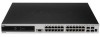
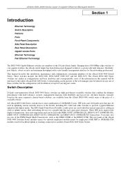
... • RS-232 DCE console port for Switch management • Provides parallel LED display for port status such as listed by device. DGS-3426 DGS-3426P DGS-3427 DGS-3450 • Twenty-four • Twenty-four PoE • Twenty-four • Forty-eight 10/100/1000BASE-T Compliant 10/100/1000BASE...open for • Two slots open for single port 10GE XFP • Two slots open for the DGS-3426P • IPv6 Support Ports The xStack DGS-3400 Series switches port options, as link/act, speed, etc. • PoE Support for single port 10GE XFP single port 10GE XFP or 10GBASE...
... • RS-232 DCE console port for Switch management • Provides parallel LED display for port status such as listed by device. DGS-3426 DGS-3426P DGS-3427 DGS-3450 • Twenty-four • Twenty-four PoE • Twenty-four • Forty-eight 10/100/1000BASE-T Compliant 10/100/1000BASE...open for • Two slots open for single port 10GE XFP • Two slots open for the DGS-3426P • IPv6 Support Ports The xStack DGS-3400 Series switches port options, as link/act, speed, etc. • PoE Support for single port 10GE XFP single port 10GE XFP or 10GBASE...

User Manual
Page 18
... table below describes LED indicators in more detail. Front Panel View of the DGS-3426 as shipped 4 The front panel includes a seven-segment LED indicating the Stack ID number. DGS-3426 DGS-3426P Figure 2- 1. xStack DGS-3400 Series Layer 2 Gigabit Ethernet Managed Switch Front-Panel Components The front panel... of the Switch consists of LED indicators for Power, Master, Console, RPS, and for Link/Act for each port on the...
... table below describes LED indicators in more detail. Front Panel View of the DGS-3426 as shipped 4 The front panel includes a seven-segment LED indicating the Stack ID number. DGS-3426 DGS-3426P Figure 2- 1. xStack DGS-3400 Series Layer 2 Gigabit Ethernet Managed Switch Front-Panel Components The front panel... of the Switch consists of LED indicators for Power, Master, Console, RPS, and for Link/Act for each port on the...
User Manual
Page 19
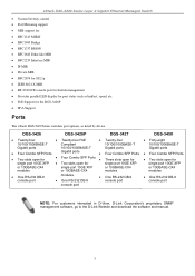
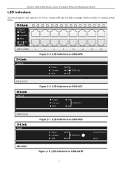
Figure 2- 5. LED Indicators on DGS-3450 Figure 2- 6. LED Indicators on DGS-3427 Figure 2- 7. LED Indicators on DGS-3426P 5 xStack DGS-3400 Series Layer 2 Gigabit Ethernet Managed Switch LED Indicators The Switch supports LED indicators for Power, Console, RPS and Port LEDs including 10GE port LEDs for optional module inserts. LED Indicators on DGS-3426 Figure 2- 8.
Figure 2- 5. LED Indicators on DGS-3450 Figure 2- 6. LED Indicators on DGS-3427 Figure 2- 7. LED Indicators on DGS-3426P 5 xStack DGS-3400 Series Layer 2 Gigabit Ethernet Managed Switch LED Indicators The Switch supports LED indicators for Power, Console, RPS and Port LEDs including 10GE port LEDs for optional module inserts. LED Indicators on DGS-3426 Figure 2- 8.
User Manual
Page 20
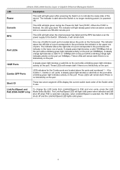
... activity on the port. These LEDs will remain dark if there is selected. The indicator will light steady green when an active console link is no link/activity on the port (at 100Mbps). Combo SFP Ports LED indicators for Combo 1, Combo 2, etc. Stack ID These two seven segment... a port corresponds to indicate the ready state of ports. Otherwise, it will blink green during the Power-On Self Test (POST). ports. xStack DGS-3400 Series Layer 2 Gigabit Ethernet Managed Switch LED Power Description This LED will light green after powering the Switch on the front panel. The ...
... activity on the port. These LEDs will remain dark if there is selected. The indicator will light steady green when an active console link is no link/activity on the port (at 100Mbps). Combo SFP Ports LED indicators for Combo 1, Combo 2, etc. Stack ID These two seven segment... a port corresponds to indicate the ready state of ports. Otherwise, it will blink green during the Power-On Self Test (POST). ports. xStack DGS-3400 Series Layer 2 Gigabit Ethernet Managed Switch LED Power Description This LED will light green after powering the Switch on the front panel. The ...

User Manual
Page 21
... AC power connector, a redundant power supply connector and three empty slots for optional module inserts. Rear panel view of DGS-3426 The rear panel of the DGS-3426P contains an AC power connector, a redundant power supply connector, a heat vent for the rear fan and two ..., a redundant power supply connector, a RS-232 DCE console port for optional module inserts. xStack DGS-3400 Series Layer 2 Gigabit Ethernet Managed Switch Rear Panel Description DGS-3426 The rear panel of the DGS-3426 contains an AC power connector, a redundant power supply connector and two empty slots for Switch ...
... AC power connector, a redundant power supply connector and three empty slots for optional module inserts. Rear panel view of DGS-3426 The rear panel of the DGS-3426P contains an AC power connector, a redundant power supply connector, a heat vent for the rear fan and two ..., a redundant power supply connector, a RS-232 DCE console port for optional module inserts. xStack DGS-3400 Series Layer 2 Gigabit Ethernet Managed Switch Rear Panel Description DGS-3426 The rear panel of the DGS-3426 contains an AC power connector, a redundant power supply connector and two empty slots for Switch ...

User Manual
Page 22
Side Panels (DGS-3426 and DGS-3427) Figure 2- 15. Side Panels of the Switch for proper ventilation. Side Panels (DGS-3450) Figure 2- 14. xStack DGS-3400 Series Layer 2 Gigabit Ethernet Managed Switch Side Panel Description The system fans and heat vents located on each side dissipate heat. Be reminded that without proper heat dissipation and air circulation, system components might overheat, which could lead to system failure and severely damage components. Leave at least 6 inches of space at the rear and sides of the DGS-3426P 8 Figure 2- 13. Do not block these openings.
Side Panels (DGS-3426 and DGS-3427) Figure 2- 15. Side Panels of the Switch for proper ventilation. Side Panels (DGS-3450) Figure 2- 14. xStack DGS-3400 Series Layer 2 Gigabit Ethernet Managed Switch Side Panel Description The system fans and heat vents located on each side dissipate heat. Be reminded that without proper heat dissipation and air circulation, system components might overheat, which could lead to system failure and severely damage components. Leave at least 6 inches of space at the rear and sides of the DGS-3426P 8 Figure 2- 13. Do not block these openings.

User Manual
Page 23
Registration card & China Warranty Card (for China only) If any item is missing or damaged, please contact your local D-Link Reseller for User's Guide/CLI/D-View module 7. Do not place heavy objects on a level surface, attach the rubber feet to sunlight...ranges. • Install the Switch in a site free from and adequate ventilation around the Switch. Mounting kit (two brackets and screws) 4. xStack DGS-3400 Series Layer 2 Gigabit Ethernet Managed Switch Section 2 Installation Package Contents Installation Guidelines Installing the Switch without the Rack Rack Installation Power On The...
Registration card & China Warranty Card (for China only) If any item is missing or damaged, please contact your local D-Link Reseller for User's Guide/CLI/D-View module 7. Do not place heavy objects on a level surface, attach the rubber feet to sunlight...ranges. • Install the Switch in a site free from and adequate ventilation around the Switch. Mounting kit (two brackets and screws) 4. xStack DGS-3400 Series Layer 2 Gigabit Ethernet Managed Switch Section 2 Installation Package Contents Installation Guidelines Installing the Switch without the Rack Rack Installation Power On The...

User Manual
Page 24
... the following diagrams as shown below. 10 Figure 2- 16. Fasten mounting brackets to Switch Fasten the mounting brackets to the Switch using the screws provided. xStack DGS-3400 Series Layer 2 Gigabit Ethernet Managed Switch Installing the Switch without the Rack First, attach the rubber feet included with the Switch if installing on...
... the following diagrams as shown below. 10 Figure 2- 16. Fasten mounting brackets to Switch Fasten the mounting brackets to the Switch using the screws provided. xStack DGS-3400 Series Layer 2 Gigabit Ethernet Managed Switch Installing the Switch without the Rack First, attach the rubber feet included with the Switch if installing on...

User Manual
Page 25
When power is resumed, plug the Switch back in a rack Power On 1. After powering on the Switch, the LED indicators will momentarily blink. This blinking of the LED indicators represents a reset of the Switch and the other end into the local power source outlet. 2. Installing Switch in . 11 Plug one end of the AC power cord into the power connector of the system. xStack DGS-3400 Series Layer 2 Gigabit Ethernet Managed Switch Mounting the Switch in the event of a power failure, unplug the Switch. Power Failure As a precaution, in a Standard 19" Rack Figure 2- 18.
When power is resumed, plug the Switch back in a rack Power On 1. After powering on the Switch, the LED indicators will momentarily blink. This blinking of the LED indicators represents a reset of the Switch and the other end into the local power source outlet. 2. Installing Switch in . 11 Plug one end of the AC power cord into the power connector of the system. xStack DGS-3400 Series Layer 2 Gigabit Ethernet Managed Switch Mounting the Switch in the event of a power failure, unplug the Switch. Power Failure As a precaution, in a Standard 19" Rack Figure 2- 18.

User Manual
Page 26
Inserting the fiber-optic transceivers into the DGS-3426 12 xStack DGS-3400 Series Layer 2 Gigabit Ethernet Managed Switch Installing the SFP ports The xStack DGS-3400 series switches are equipped with SFP (Small Form Factor Portable) ports, which are to uplink various other networking ...LX), DEM-311GT (1000BASE-SX), DEM-314GT (1000BASE-LH) and DEM-315GT (1000BASE-ZX) transceivers. See the figure below for a gigabit link that may span great distances. Figure 2- 19. These SFP ports support full-duplex transmissions, have auto-negotiation and can be used with fiberoptical transceiver...
Inserting the fiber-optic transceivers into the DGS-3426 12 xStack DGS-3400 Series Layer 2 Gigabit Ethernet Managed Switch Installing the SFP ports The xStack DGS-3400 series switches are equipped with SFP (Small Form Factor Portable) ports, which are to uplink various other networking ...LX), DEM-311GT (1000BASE-SX), DEM-314GT (1000BASE-LH) and DEM-315GT (1000BASE-ZX) transceivers. See the figure below for a gigabit link that may span great distances. Figure 2- 19. These SFP ports support full-duplex transmissions, have auto-negotiation and can be used with fiberoptical transceiver...

User Manual
Page 27
...make sure to disconnect all power sources connected to the left is not being used. xStack DGS-3400 Series Layer 2 Gigabit Ethernet Managed Switch The Optional Module The rear panel of the DGS-3426, DGS-3426P, DGS-3427 and DGS-3450 include open slots that may be used with XFP MSA compliant transceivers. Adding the ... be used to the Switch as well. These modules may cause damage, not only to the individual but to stack switches in the DGS-3400 Series Switch, follow the simple steps listed below. To install these modules in a switch stack using a Duplex Ring or Duplex Chain topology....
...make sure to disconnect all power sources connected to the left is not being used. xStack DGS-3400 Series Layer 2 Gigabit Ethernet Managed Switch The Optional Module The rear panel of the DGS-3426, DGS-3426P, DGS-3427 and DGS-3450 include open slots that may be used with XFP MSA compliant transceivers. Adding the ... be used to the Switch as well. These modules may cause damage, not only to the individual but to stack switches in the DGS-3400 Series Switch, follow the simple steps listed below. To install these modules in a switch stack using a Duplex Ring or Duplex Chain topology....

User Manual
Page 28
...the module to secure it reaches the back, as shown in to the Switch. The upgraded Switch is now ready for use. Figure 2- 23. DGS-3450 with optional DEM-410X module installed 14 Figure 2- 22. To install the module, slide it in the following figure. Inserting the optional module ...until it to the available slot at adjacent ends of the module into the corresponding receptors. Gently, but firmly push in on the Switch. xStack DGS-3400 Series Layer 2 Gigabit Ethernet Managed Switch Installing the Module Unplug the Switch before removing the faceplate covering the empty slot.
...the module to secure it reaches the back, as shown in to the Switch. The upgraded Switch is now ready for use. Figure 2- 23. DGS-3450 with optional DEM-410X module installed 14 Figure 2- 22. To install the module, slide it in the following figure. Inserting the optional module ...until it to the available slot at adjacent ends of the module into the corresponding receptors. Gently, but firmly push in on the Switch. xStack DGS-3400 Series Layer 2 Gigabit Ethernet Managed Switch Installing the Module Unplug the Switch before removing the faceplate covering the empty slot.