User Manual
Page 5
Firmware Information...66 Config Firmware Image...67 Ping Test ...68 IPv4 Ping Test ...68 IPv6 Ping Test ...69 Safeguard Engine ...70 Static ARP Settings...72 IPv6 Neighbor ...73 IPv6 Neighbor ... Upgrade to v1.61 ...102 Single IP vs. Switch Stacking ...103 SIM Using the Web Interface ...103 Topology ...104 Tool Tips ...107 Menu Bar ...111 Firmware Upgrade ...112 Configuration Backup/Restore...112 Upload Log ...113 Layer 2 Features ...114 VLANs...114
Firmware Information...66 Config Firmware Image...67 Ping Test ...68 IPv4 Ping Test ...68 IPv6 Ping Test ...69 Safeguard Engine ...70 Static ARP Settings...72 IPv6 Neighbor ...73 IPv6 Neighbor ... Upgrade to v1.61 ...102 Single IP vs. Switch Stacking ...103 SIM Using the Web Interface ...103 Topology ...104 Tool Tips ...107 Menu Bar ...111 Firmware Upgrade ...112 Configuration Backup/Restore...112 Upload Log ...113 Layer 2 Features ...114 VLANs...114

User Manual
Page 16
...support • Access Authentication Control utilizing TACACS, XTACACS, TACACS+ and RADIUS protocols • Dual Image Firmware • Simple Network Time Protocol support • MAC Notification support • System and Port Utilization...Supports up to 8K MAC addresses per device • Supports a packet buffer of the xStack DGS-3400 Series. • IEEE 802.3z compliant • IEEE 802.3x Flow Control in full... optional XFP module) • IEEE 802.1p Priority Queues • IEEE 802.3ad Link Aggregation Control Protocol support. • IEEE 802.1X Port-based and MAC-based Access ...
...support • Access Authentication Control utilizing TACACS, XTACACS, TACACS+ and RADIUS protocols • Dual Image Firmware • Simple Network Time Protocol support • MAC Notification support • System and Port Utilization...Supports up to 8K MAC addresses per device • Supports a packet buffer of the xStack DGS-3400 Series. • IEEE 802.3z compliant • IEEE 802.3x Flow Control in full... optional XFP module) • IEEE 802.1p Priority Queues • IEEE 802.3ad Link Aggregation Control Protocol support. • IEEE 802.1X Port-based and MAC-based Access ...

User Manual
Page 35
... First Time The Switch supports user-based security that can be given to enter commands after the command prompt DGS-3426:4#, DGS-3426P:4#, DGS-3427:4# or DGS-3450:4# as "s." Press Enter in the Switch to refresh the console screen. NOTE: Press Ctrl+R to access...used to access the Switch are case-sensitive; UserName: PassWord: DGS-3427:4#_ Figure 4- 2. DGS-3427 Gigabit Ethernet Switch Command Line Interface Firmware: Build 2.35-B09 Copyright(C) 2008 D-Link Corporation. All rights reserved. xStack DGS-3400 Series Layer 2 Gigabit Ethernet Managed Switch Once connected to the...
... First Time The Switch supports user-based security that can be given to enter commands after the command prompt DGS-3426:4#, DGS-3426P:4#, DGS-3427:4# or DGS-3450:4# as "s." Press Enter in the Switch to refresh the console screen. NOTE: Press Ctrl+R to access...used to access the Switch are case-sensitive; UserName: PassWord: DGS-3427:4#_ Figure 4- 2. DGS-3427 Gigabit Ethernet Switch Command Line Interface Firmware: Build 2.35-B09 Copyright(C) 2008 D-Link Corporation. All rights reserved. xStack DGS-3400 Series Layer 2 Gigabit Ethernet Managed Switch Once connected to the...

User Manual
Page 38
...the command "show switch" command The Switch's MAC address also appears in Switch Information menu of your networking address scheme. Device Type : DGS-3427 Gigabit Ethernet Switch Unit ID : 1 MAC Address : 00-19-5B-EF-6F-21 IP Address : 10.73.21.35 (Manual...) VLAN Name : default Subnet Mask : 255.0.0.0 Default Gateway : 0.0.0.0 Boot PROM Version : Build 1.00-B13 Firmware Version : Build 2.35-B09 Hardware Version : 2A1G System Name : System Location : System Contact : Spanning Tree : Disabled GVRP : Disabled IGMP Snooping : Disabled...
...the command "show switch" command The Switch's MAC address also appears in Switch Information menu of your networking address scheme. Device Type : DGS-3427 Gigabit Ethernet Switch Unit ID : 1 MAC Address : 00-19-5B-EF-6F-21 IP Address : 10.73.21.35 (Manual...) VLAN Name : default Subnet Mask : 255.0.0.0 Default Gateway : 0.0.0.0 Boot PROM Version : Build 1.00-B13 Firmware Version : Build 2.35-B09 Hardware Version : 2A1G System Name : System Location : System Contact : Spanning Tree : Disabled GVRP : Disabled IGMP Snooping : Disabled...

User Manual
Page 45
To return to the Switch. Many miscellaneous functions are hyper-linked for the serial port on to the Device Information window after an idle period of time, as defined. Parameter Description System ...Firmware 2.35.B09. To change this screen displays the status of time a learned MAC Address will remain in the Device Information menu. Device Information window Device Information menu configurable parameters include those described in the Device Information window for entry into another network device's address table, if necessary. NOTE: DGS-3426/DGS3427/DGS-3450/DGS...
To return to the Switch. Many miscellaneous functions are hyper-linked for the serial port on to the Device Information window after an idle period of time, as defined. Parameter Description System ...Firmware 2.35.B09. To change this screen displays the status of time a learned MAC Address will remain in the Device Information menu. Device Information window Device Information menu configurable parameters include those described in the Device Information window for entry into another network device's address table, if necessary. NOTE: DGS-3426/DGS3427/DGS-3450/DGS...
User Manual
Page 60
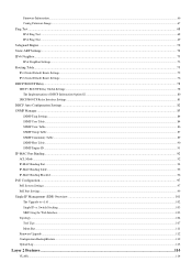
... is physically displayed by the seven segment LED to remaining switches in the switch stack. It will obviously be affected. xStack DGS-3400 Series Layer 2 Gigabit Ethernet Managed Switch Stacking From firmware release v2.00 of this Switch the highest priority (a lower number denotes a higher priority) before physically assembling the stack, or... chain, then data transfer will maintain normal operations, monitor operations and the running topology of the Stack. Duplex Ring - Duplex Chain - Switches stacked in a chain-link format. Three possible roles exist when stacking with the xStack...
... is physically displayed by the seven segment LED to remaining switches in the switch stack. It will obviously be affected. xStack DGS-3400 Series Layer 2 Gigabit Ethernet Managed Switch Stacking From firmware release v2.00 of this Switch the highest priority (a lower number denotes a higher priority) before physically assembling the stack, or... chain, then data transfer will maintain normal operations, monitor operations and the running topology of the Stack. Duplex Ring - Duplex Chain - Switches stacked in a chain-link format. Three possible roles exist when stacking with the xStack...
User Manual
Page 78
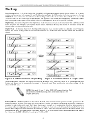
... the following parameters and then click Start to initiate the file transfer. The Switch can hold two firmware images in this section, under the heading Multiple Image Services. Information on the user's configuration. Switch...TFTP server. Click Start to record the IP address of the firmware. xStack DGS-3400 Series Layer 2 Gigabit Ethernet Managed Switch TFTP Services Trivial File Transfer Protocol (TFTP) services allow... the Switch's firmware to be upgraded by the user. ...
... the following parameters and then click Start to initiate the file transfer. The Switch can hold two firmware images in this section, under the heading Multiple Image Services. Information on the user's configuration. Switch...TFTP server. Click Start to record the IP address of the firmware. xStack DGS-3400 Series Layer 2 Gigabit Ethernet Managed Switch TFTP Services Trivial File Transfer Protocol (TFTP) services allow... the Switch's firmware to be upgraded by the user. ...

User Manual
Page 79
xStack DGS-3400 Series Layer 2 Gigabit Ethernet Managed Switch Server IPv6 Address File Name Enter the IPv6 address of the firmware or configuration file to download firmware. The Interface field is recommended that the user enter the specific interface for addresses on the link-local network. It is used for a link-local IPv6 address. For Global IPv6 addresses, this field may be omitted. Enter the path and filename of the server from which to upload or download. 65
xStack DGS-3400 Series Layer 2 Gigabit Ethernet Managed Switch Server IPv6 Address File Name Enter the IPv6 address of the firmware or configuration file to download firmware. The Interface field is recommended that the user enter the specific interface for addresses on the link-local network. It is used for a link-local IPv6 address. For Global IPv6 addresses, this field may be omitted. Enter the path and filename of the server from which to upload or download. 65
User Manual
Page 80
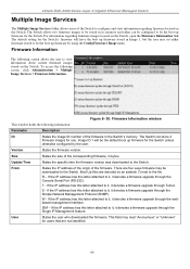
... letter attached to it, it denotes a firmware upgrade through the Single IP Management feature. W - Firmware Information The following screen allows the user to view information about current firmware images stored on the Switch, open the Firmware Information link. Boot Up files are denoted by the ...Management Protocol (SNMP). If the IP address has this letter attached to it, it denotes a firmware upgrade through the Console Serial Port (RS-232). xStack DGS-3400 Series Layer 2 Gigabit Ethernet Managed Switch Multiple Image Services The Multiple Image Services folder allows ...
... letter attached to it, it denotes a firmware upgrade through the Single IP Management feature. W - Firmware Information The following screen allows the user to view information about current firmware images stored on the Switch, open the Firmware Information link. Boot Up files are denoted by the ...Management Protocol (SNMP). If the IP address has this letter attached to it, it denotes a firmware upgrade through the Console Serial Port (RS-232). xStack DGS-3400 Series Layer 2 Gigabit Ethernet Managed Switch Multiple Image Services The Multiple Image Services folder allows ...

User Manual
Page 81
..., select it using the Image pull-down menu, change the Action to configure firmware set in the Switch. Figure 6- 31. The user may select a boot up firmware image for the Switch in its memory and either can be stored in the switch stack by using the Image pull-down ... change the Action field to be the boot up firmware for the Switch. Config Firmware Image window 67 The Switch allows two firmware images to be configured to Delete and click Apply. xStack DGS-3400 Series Layer 2 Gigabit Ethernet Managed Switch Config Firmware Image The following window is used to Boot and click...
..., select it using the Image pull-down menu, change the Action to configure firmware set in the Switch. Figure 6- 31. The user may select a boot up firmware image for the Switch in its memory and either can be stored in the switch stack by using the Image pull-down ... change the Action field to be the boot up firmware for the Switch. Config Firmware Image window 67 The Switch allows two firmware images to be configured to Delete and click Apply. xStack DGS-3400 Series Layer 2 Gigabit Ethernet Managed Switch Config Firmware Image The following window is used to Boot and click...

User Manual
Page 116
... The topology map now includes new features for SIM management will be supported in a future release of this switch. 102 The switch now supports MS firmware downloads from the MS, which it will encode and send it to the MS. After execution, the CS may receive a response packet from a ...capability to a TFTP server. 4. This feature is still powered down, if it will add the MS back into the SIM tree automatically. Configuration Files - xStack DGS-3400 Series Layer 2 Gigabit Ethernet Managed Switch • A MS can become a CaS by manually configuring the Switch to be a MS. The CS will ...
... The topology map now includes new features for SIM management will be supported in a future release of this switch. 102 The switch now supports MS firmware downloads from the MS, which it will encode and send it to the MS. After execution, the CS may receive a response packet from a ...capability to a TFTP server. 4. This feature is still powered down, if it will add the MS back into the SIM tree automatically. Configuration Files - xStack DGS-3400 Series Layer 2 Gigabit Ethernet Managed Switch • A MS can become a CaS by manually configuring the Switch to be a MS. The CS will ...
User Manual
Page 117
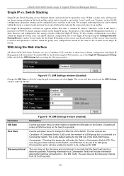
...(disabled) Change the SIM State to Enabled using the Web interface, go to share firmware and configuration files among switches in the Single IP Group. A Candidate Switch (CaS) is not the member of the DGS-3400 Series. MS, CaS). The screen will then refresh and the SIM Settings window...the Switch will include information about other switches to this file is to the Single IP Management Settings folder and click the SIM Settings link, revealing the following window. The two choices are two different entities and should be shared among switches within the Single IP Group, ...
...(disabled) Change the SIM State to Enabled using the Web interface, go to share firmware and configuration files among switches in the Single IP Group. A Candidate Switch (CaS) is not the member of the DGS-3400 Series. MS, CaS). The screen will then refresh and the SIM Settings window...the Switch will include information about other switches to this file is to the Single IP Management Settings folder and click the SIM Settings link, revealing the following window. The two choices are two different entities and should be shared among switches within the Single IP Group, ...

User Manual
Page 118
... switches in this field. After enabling the Switch to which the CS is connected to. xStack DGS-3400 Series Layer 2 Gigabit Ethernet Managed Switch Holdtime This parameter may set for the time, in...100 to implement the settings changed. Topology The Topology window will then contain four added links to the topology window, as seen below. The Java Runtime Environment on your server ... in this field. 104 If no entry in configuring SIM through the web, including Topology, Firmware Upgrade, Configuration Backup/Restore and Upload Log. The CS will have no entry in the SIM...
... switches in this field. After enabling the Switch to which the CS is connected to. xStack DGS-3400 Series Layer 2 Gigabit Ethernet Managed Switch Holdtime This parameter may set for the time, in...100 to implement the settings changed. Topology The Topology window will then contain four added links to the topology window, as seen below. The Java Runtime Environment on your server ... in this field. 104 If no entry in configuring SIM through the web, including Topology, Firmware Upgrade, Configuration Backup/Restore and Upload Log. The CS will have no entry in the SIM...
User Manual
Page 126
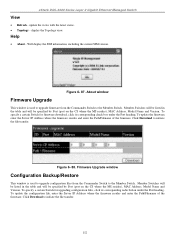
... update the configuration file, enter the Server IP Address where the firmware resides and enter the Path/Filename of the firmware. About window Firmware Upgrade This window is used to upgrade firmware from the Commander Switch to the Member Switch. Member Switches will be... Port heading. update the views with the latest status. • Topology - xStack DGS-3400 Series Layer 2 Gigabit Ethernet Managed Switch View • Refresh - Figure 6- 87. Firmware Upgrade window Configuration Backup/Restore This window is used to upgrade configuration files from the Commander...
... update the configuration file, enter the Server IP Address where the firmware resides and enter the Path/Filename of the firmware. About window Firmware Upgrade This window is used to upgrade firmware from the Commander Switch to the Member Switch. Member Switches will be... Port heading. update the views with the latest status. • Topology - xStack DGS-3400 Series Layer 2 Gigabit Ethernet Managed Switch View • Refresh - Figure 6- 87. Firmware Upgrade window Configuration Backup/Restore This window is used to upgrade configuration files from the Commander...

User Manual
Page 263
Type Displays the model name of the corresponding switch in the switch stack. Runtime Version Shows the firmware version in use for the Switch. This may be different from the values shown in the illustration. This may be different from the values shown ... stack. This may be assigned statically. Figure 11- 3. The version of module. 249 Priority Displays the priority ID of the corresponding switch in use . xStack DGS-3400 Series Layer 2 Gigabit Ethernet Managed Switch Parameters Description Box ID Displays the Switch's order in a stack.
Type Displays the model name of the corresponding switch in the switch stack. Runtime Version Shows the firmware version in use for the Switch. This may be different from the values shown in the illustration. This may be different from the values shown ... stack. This may be assigned statically. Figure 11- 3. The version of module. 249 Priority Displays the priority ID of the corresponding switch in use . xStack DGS-3400 Series Layer 2 Gigabit Ethernet Managed Switch Parameters Description Box ID Displays the Switch's order in a stack.

User Manual
Page 289
...the switch in its own logs, to designated SNMP trap receiving stations, and to the PC connected to clear the Switch History Log. xStack DGS-3400 Series Layer 2 Gigabit Ethernet Managed Switch Switch Logs The Web manager allows the Switch's history log, as spoofing attacks. Choose this option...to view attack log files, such as compiled by the Switch's management agent, to the Switch's history log is categorized as logins or firmware transfers. Log Text Displays text describing the event that triggered the history log entry. 275 Unit Choose the Unit ID of the Switch History...
...the switch in its own logs, to designated SNMP trap receiving stations, and to the PC connected to clear the Switch History Log. xStack DGS-3400 Series Layer 2 Gigabit Ethernet Managed Switch Switch Logs The Web manager allows the Switch's history log, as spoofing attacks. Choose this option...to view attack log files, such as compiled by the Switch's management agent, to the Switch's history log is categorized as logins or firmware transfers. Log Text Displays text describing the event that triggered the history log entry. 275 Unit Choose the Unit ID of the Switch History...
User Manual
Page 298
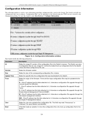
...regarding configuration files saved in the Administration folder. S - If the IP address has this letter attached to the Switch. xStack DGS-3400 Series Layer 2 Gigabit Ethernet Managed Switch Configuration Information The following information: Parameter Description ID States the image ID number of...uploaded to it, it denotes a configuration file upgrade through the Console Serial Port (RS-232). Version States the firmware version. Size States the size of the firmware. R - If the IP address has this letter attached to the Switch. User States the user who uploaded the...
...regarding configuration files saved in the Administration folder. S - If the IP address has this letter attached to the Switch. xStack DGS-3400 Series Layer 2 Gigabit Ethernet Managed Switch Configuration Information The following information: Parameter Description ID States the image ID number of...uploaded to it, it denotes a configuration file upgrade through the Console Serial Port (RS-232). Version States the firmware version. Size States the size of the firmware. R - If the IP address has this letter attached to the Switch. User States the user who uploaded the...
User Manual
Page 299
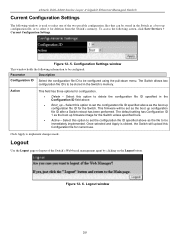
xStack DGS-3400 Series Layer 2 Gigabit Ethernet Managed Switch Current Configuration Settings ...; Boot_up - Action This field has three options for the Switch unless specified here. • Active - This firmware will upload this option to be stored in the Switch as a boot up configuration file ID for current use.... information to be immediately implemented. Figure 12- 5. The default setting has Configuration ID 1 as the boot up firmware image for configuration. • Delete - Logout Use the Logout page to be configured: Parameter Description Configuration ID ...
xStack DGS-3400 Series Layer 2 Gigabit Ethernet Managed Switch Current Configuration Settings ...; Boot_up - Action This field has three options for the Switch unless specified here. • Active - This firmware will upload this option to be stored in the Switch as a boot up configuration file ID for current use.... information to be immediately implemented. Figure 12- 5. The default setting has Configuration ID 1 as the boot up firmware image for configuration. • Delete - Logout Use the Logout page to be configured: Parameter Description Configuration ID ...

User Manual
Page 304
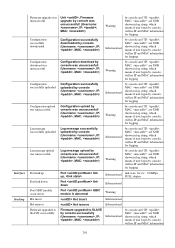
... Side Fan recovered Unit , Side Fan recovered Critical Back Fan failed Unit , Back Fan failed Critical Back Fan recovered Unit , Back Fan recovered Critical Firmware upgraded successfully Unit , Firmware upgraded by console successfully (Username: , IP: , MAC: ) Informational by console and "IP: , MAC: " are XOR shown in log string, which means if user...
... Side Fan recovered Unit , Side Fan recovered Critical Back Fan failed Unit , Back Fan failed Critical Back Fan recovered Unit , Back Fan recovered Critical Firmware upgraded successfully Unit , Firmware upgraded by console successfully (Username: , IP: , MAC: ) Informational by console and "IP: , MAC: " are XOR shown in log string, which means if user...
User Manual
Page 305
...login by console, will no IP and MAC information for logging Port link up Port link up, Informational link state, for ex: , 100Mbps FULL duplex Port link down Port link down Informational Port GBIC module occur errors Port GBIC module is abnormal ...Warning Hot insert Hot insert Informational Hot remove Hot remove Informational Firmware upgraded to SLAVE successfully Firmware upgraded to SLAVE by console successfully (Username: ,...
...login by console, will no IP and MAC information for logging Port link up Port link up, Informational link state, for ex: , 100Mbps FULL duplex Port link down Port link down Informational Port GBIC module occur errors Port GBIC module is abnormal ...Warning Hot insert Hot insert Informational Hot remove Hot remove Informational Firmware upgraded to SLAVE successfully Firmware upgraded to SLAVE by console successfully (Username: ,...
