User Manual
Page 3
... to End Node ...17 Switch to Switch ...17 Connecting To Network Backbone or Server ...18 Introduction to Switch Management ...19 Management Options...19 Connecting the Console Port (RS-232 DCE)...20 Managing the Switch for the First Time ...21 Password Protection...22 IP Address Assignment...24 Web-based Switch Configuration...26...
... to End Node ...17 Switch to Switch ...17 Connecting To Network Backbone or Server ...18 Introduction to Switch Management ...19 Management Options...19 Connecting the Console Port (RS-232 DCE)...20 Managing the Switch for the First Time ...21 Password Protection...22 IP Address Assignment...24 Web-based Switch Configuration...26...

User Manual
Page 4
... Detection ...37 Duplicate Address Detection (DAD) ...38 Assigning IP Addresses ...38 IP Interface Setup ...38 IP Address ...39 Setting the Switch's IP Address using the Console Interface ...40 Interface Settings...41 IPv4 Interface Settings...41 IPv6 Interface Settings...42 Stacking...46 Stack Switch Swapping ...47 Stacking Mode Settings ...48 Box Information...
... Detection ...37 Duplicate Address Detection (DAD) ...38 Assigning IP Addresses ...38 IP Interface Setup ...38 IP Address ...39 Setting the Switch's IP Address using the Console Interface ...40 Interface Settings...41 IPv4 Interface Settings...41 IPv6 Interface Settings...42 Stacking...46 Stack Switch Swapping ...47 Stacking Mode Settings ...48 Box Information...
User Manual
Page 17
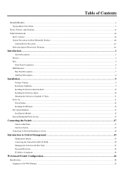
DGS-3426 DGS-3426P DGS-3427 DGS-3450 • Twenty-four • Twenty-four PoE • Twenty-four • Forty-eight 10/100/1000BASE-T Compliant 10/100/1000BASE-T 10/100/1000BASE-T Gigabit ... MIB • Private MIB • RFC2674 for 802.1p • IEEE 802.1X MIB • RS-232 DCE console port for Switch management • Provides parallel LED display for port status such as link/act, speed, etc. • PoE Support for single port 10GE XFP single port 10GE XFP or 10GBASE-CX4...
DGS-3426 DGS-3426P DGS-3427 DGS-3450 • Twenty-four • Twenty-four PoE • Twenty-four • Forty-eight 10/100/1000BASE-T Compliant 10/100/1000BASE-T 10/100/1000BASE-T Gigabit ... MIB • Private MIB • RFC2674 for 802.1p • IEEE 802.1X MIB • RS-232 DCE console port for Switch management • Provides parallel LED display for port status such as link/act, speed, etc. • PoE Support for single port 10GE XFP single port 10GE XFP or 10GBASE-CX4...

User Manual
Page 18
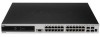
...-segment LED indicating the Stack ID number. DGS-3426 DGS-3426P Figure 2- 1. Front Panel View of the DGS-3426P as shipped 4 Front Panel View of the DGS-3450 as shipped DGS-3450 Figure 2- 3. Front Panel View of the DGS-3426 as shipped Figure 2- 4. DGS-3426P also includes a Mode Select button for...table below describes LED indicators in more detail. xStack DGS-3400 Series Layer 2 Gigabit Ethernet Managed Switch Front-Panel Components The front panel of the Switch consists of LED indicators for Power, Master, Console, RPS, and for Link/Act for each port on the Switch including 10GE...
...-segment LED indicating the Stack ID number. DGS-3426 DGS-3426P Figure 2- 1. Front Panel View of the DGS-3426P as shipped 4 Front Panel View of the DGS-3450 as shipped DGS-3450 Figure 2- 3. Front Panel View of the DGS-3426 as shipped Figure 2- 4. DGS-3426P also includes a Mode Select button for...table below describes LED indicators in more detail. xStack DGS-3400 Series Layer 2 Gigabit Ethernet Managed Switch Front-Panel Components The front panel of the Switch consists of LED indicators for Power, Master, Console, RPS, and for Link/Act for each port on the Switch including 10GE...
User Manual
Page 19
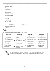
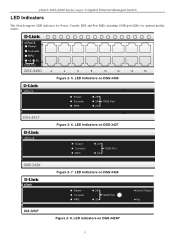
LED Indicators on DGS-3426P 5 LED Indicators on DGS-3426 Figure 2- 8. LED Indicators on DGS-3450 Figure 2- 6. xStack DGS-3400 Series Layer 2 Gigabit Ethernet Managed Switch LED Indicators The Switch supports LED indicators for Power, Console, RPS and Port LEDs including 10GE port LEDs for optional module inserts. Figure 2- 5. LED Indicators on DGS-3427 Figure 2- 7.
LED Indicators on DGS-3426P 5 LED Indicators on DGS-3426 Figure 2- 8. LED Indicators on DGS-3450 Figure 2- 6. xStack DGS-3400 Series Layer 2 Gigabit Ethernet Managed Switch LED Indicators The Switch supports LED indicators for Power, Console, RPS and Port LEDs including 10GE port LEDs for optional module inserts. Figure 2- 5. LED Indicators on DGS-3427 Figure 2- 7.
User Manual
Page 20
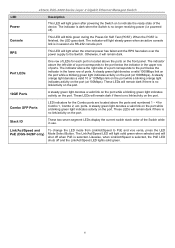
... LEDs will light steady green when an active console link is finished, the LED goes dark. Likewise, when Link/Act/Speed is selected, the PoE LED shuts off when PoE is no link/activity on the port. 10GE Ports A steady green light denotes a valid link on the port while a blinking green light ...RPS This LED will remain dark if there is no link/activity on the port (at 1000Mbps). A steady orange light denotes a valid 10 or 100Mbps link on the port while a blinking orange light indicates activity on the port. Link/Act/Speed and PoE (DGS-3426P only) To change the LED mode from...
... LEDs will light steady green when an active console link is finished, the LED goes dark. Likewise, when Link/Act/Speed is selected, the PoE LED shuts off when PoE is no link/activity on the port. 10GE Ports A steady green light denotes a valid link on the port while a blinking green light ...RPS This LED will remain dark if there is no link/activity on the port (at 1000Mbps). A steady orange light denotes a valid 10 or 100Mbps link on the port while a blinking orange light indicates activity on the port. Link/Act/Speed and PoE (DGS-3426P only) To change the LED mode from...

User Manual
Page 21
... supply connector, a RS-232 DCE console port for Switch management and a system fan vent. DGS-3427 Figure 2- 10. Figure 2- 12. The rear panel also includes an outlet for the Switch immediately. 7 DGS-3450 Figure 2- 11. Rear panel view of the DGS-3427 contains an AC power connector, ...an optional external power supply. Rear panel view of DGS-3427 The rear panel of the cord into a power outlet. xStack DGS-3400 Series Layer 2 Gigabit Ethernet Managed Switch Rear Panel Description DGS-3426 The rear panel of the DGS-3426P contains an AC power connector, a redundant power ...
... supply connector, a RS-232 DCE console port for Switch management and a system fan vent. DGS-3427 Figure 2- 10. Figure 2- 12. The rear panel also includes an outlet for the Switch immediately. 7 DGS-3450 Figure 2- 11. Rear panel view of the DGS-3427 contains an AC power connector, ...an optional external power supply. Rear panel view of DGS-3427 The rear panel of the cord into a power outlet. xStack DGS-3400 Series Layer 2 Gigabit Ethernet Managed Switch Rear Panel Description DGS-3426 The rear panel of the DGS-3426P contains an AC power connector, a redundant power ...

User Manual
Page 23
...• Make sure that there is missing or damaged, please contact your local D-Link Reseller for China only) If any item is proper heat dissipation from scratching other surfaces... sturdy, level surface that it from and adequate ventilation around the Switch. xStack DGS-3400 Series Layer 2 Gigabit Ethernet Managed Switch Section 2 Installation Package Contents Installation ... Switch. • The power outlet should contain the following items: 1. RS-232 console cable 6. Installation Guidelines Please follow these guidelines for the acceptable temperature and humidity operating ...
...• Make sure that there is missing or damaged, please contact your local D-Link Reseller for China only) If any item is proper heat dissipation from scratching other surfaces... sturdy, level surface that it from and adequate ventilation around the Switch. xStack DGS-3400 Series Layer 2 Gigabit Ethernet Managed Switch Section 2 Installation Package Contents Installation ... Switch. • The power outlet should contain the following items: 1. RS-232 console cable 6. Installation Guidelines Please follow these guidelines for the acceptable temperature and humidity operating ...
User Manual
Page 33
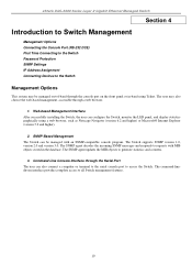
...The SNMP agent updates the MIB objects to requests with an SNMP-compatible console program. The SNMP agent decodes the incoming SNMP messages and responds to generate statistics and counters. 3. xStack DGS-3400 Series Layer 2 Gigabit Ethernet Managed Switch Section 4 Introduction to ...Switch Management Management Options Connecting the Console Port (RS-232 DCE) First Time Connecting to the Switch Password...
...The SNMP agent updates the MIB objects to requests with an SNMP-compatible console program. The SNMP agent decodes the incoming SNMP messages and responds to generate statistics and counters. 3. xStack DGS-3400 Series Layer 2 Gigabit Ethernet Managed Switch Section 4 Introduction to ...Switch Management Management Options Connecting the Console Port (RS-232 DCE) First Time Connecting to the Switch Password...
User Manual
Page 34
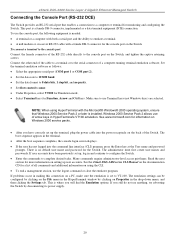
..., try rebooting the Switch by clicking on the Switch. NOTE: When using the CLI. • To end a management session, use the console port, the following equipment is where you have been previously set to none. • Under Properties, select VT100 for Emulation mode. •...2 allows use Terminal keys (not Windows keys) are selected. Many commands require administrator-level access privileges. xStack DGS-3400 Series Layer 2 Gigabit Ethernet Managed Switch Connecting the Console Port (RS-232 DCE) The Switch provides an RS-232 serial port that Windows 2000 Service Pack 2 or...
..., try rebooting the Switch by clicking on the Switch. NOTE: When using the CLI. • To end a management session, use the console port, the following equipment is where you have been previously set to none. • Under Properties, select VT100 for Emulation mode. •...2 allows use Terminal keys (not Windows keys) are selected. Many commands require administrator-level access privileges. xStack DGS-3400 Series Layer 2 Gigabit Ethernet Managed Switch Connecting the Console Port (RS-232 DCE) The Switch provides an RS-232 serial port that Windows 2000 Service Pack 2 or...

User Manual
Page 35
... name or password and therefore just press enter twice to access the command line interface. Then access will appear on the console screen. All rights reserved. DGS-3427 Gigabit Ethernet Switch Command Line Interface Firmware: Build 2.35-B09 Copyright(C) 2008 D-Link Corporation. Initial Screen after the command prompt DGS-3426:4#, DGS-3426P:4#, DGS-3427:4# or DGS-3450:4# as "s."
... name or password and therefore just press enter twice to access the command line interface. Then access will appear on the console screen. All rights reserved. DGS-3427 Gigabit Ethernet Switch Command Line Interface Firmware: Build 2.35-B09 Copyright(C) 2008 D-Link Corporation. Initial Screen after the command prompt DGS-3426:4#, DGS-3426P:4#, DGS-3427:4# or DGS-3450:4# as "s."

User Manual
Page 38
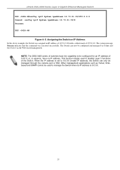
... user may be set using the Command Line Interface (CLI) over the console serial port as shown below. "show switch" into the command line interface...x's represent the IP address to be assigned to the Switch's Telnet or Web-based management agent. 24 Device Type : DGS-3427 Gigabit Ethernet Switch Unit ID : 1 MAC Address : 00-19-5B-EF-6F-21 IP Address : 10.73... by entering the command "show switch" command The Switch's MAC address also appears in CIDR notation. xStack DGS-3400 Series Layer 2 Gigabit Ethernet Managed Switch IP Address Assignment An IP Address must be assigned to the ...
... user may be set using the Command Line Interface (CLI) over the console serial port as shown below. "show switch" into the command line interface...x's represent the IP address to be assigned to the Switch's Telnet or Web-based management agent. 24 Device Type : DGS-3427 Gigabit Ethernet Switch Unit ID : 1 MAC Address : 00-19-5B-EF-6F-21 IP Address : 10.73... by entering the command "show switch" command The Switch's MAC address also appears in CIDR notation. xStack DGS-3400 Series Layer 2 Gigabit Ethernet Managed Switch IP Address Assignment An IP Address must be assigned to the ...
User Manual
Page 39
... used to be configured and managed via Telnet and the CLI or via the Web-based management. The Switch can only be managed through the console port or SIM. This function maybe used to manage the Switch when its IP address is set to 0.0.0.0 (invalid IP address), the Switch...be configured for an IP address of the Switch. NOTE: The DGS-3400 series of switches have the capability to disable Layer 3 functions of 0.0.0.0, or, in essence, have no IP address. xStack DGS-3400 Series Layer 2 Gigabit Ethernet Managed Switch DGS -3426:4#config ipif System ipaddress 10.73.21.35/255.0.0.0 Comand: ...
... used to be configured and managed via Telnet and the CLI or via the Web-based management. The Switch can only be managed through the console port or SIM. This function maybe used to manage the Switch when its IP address is set to 0.0.0.0 (invalid IP address), the Switch...be configured for an IP address of the Switch. NOTE: The DGS-3400 series of switches have the capability to disable Layer 3 functions of 0.0.0.0, or, in essence, have no IP address. xStack DGS-3400 Series Layer 2 Gigabit Ethernet Managed Switch DGS -3426:4#config ipif System ipaddress 10.73.21.35/255.0.0.0 Comand: ...
User Manual
Page 40
... are different ways to access the same internal switching software and configure it to the IP address you have defined for the device. xStack DGS-3400 Series Layer 2 Gigabit Ethernet Managed Switch Section 5 Web-based Switch Configuration Introduction Logging on your computer and point it . Thus,... Network Management Switch Utilities Network Monitoring IGMP Snooping Status Introduction All software functions of the Switch. The Web-based management module and the Console program (and Telnet) are the same as those found in the address bar should read something like: http://123.123.123.123,...
... are different ways to access the same internal switching software and configure it to the IP address you have defined for the device. xStack DGS-3400 Series Layer 2 Gigabit Ethernet Managed Switch Section 5 Web-based Switch Configuration Introduction Logging on your computer and point it . Thus,... Network Management Switch Utilities Network Monitoring IGMP Snooping Status Introduction All software functions of the Switch. The Web-based management module and the Console program (and Telnet) are the same as those found in the address bar should read something like: http://123.123.123.123,...

User Manual
Page 45
... Enter a system name for the console interface. This automatically logs the user out after viewing other windows, click the DGS-3400 Web Management Tool folder. This... log on the Switch to keep track of time, as defined. NOTE: DGS-3426/DGS3427/DGS-3450/DGS-3426P will identify it in seconds. The default setting is 10 minutes. The... 31 In addition, this , type in a different value representing the MAC address age-out time in the Switch network. Many miscellaneous functions are hyper-linked...
... Enter a system name for the console interface. This automatically logs the user out after viewing other windows, click the DGS-3400 Web Management Tool folder. This... log on the Switch to keep track of time, as defined. NOTE: DGS-3426/DGS3427/DGS-3450/DGS-3426P will identify it in seconds. The default setting is 10 minutes. The... 31 In addition, this , type in a different value representing the MAC address age-out time in the Switch network. Many miscellaneous functions are hyper-linked...

User Manual
Page 53
... configured VLANs, the user will access the Switch. If the Switch IP address has not yet been changed, read the introduction of the xStack DGS-3400 Series CLI Manual or return to the management station that will need to enter the VLAN ID of the Switch ports as seen below...: pull-down menu to it through the Ethernet. The Switch will display the Switch's current IP settings in the IP configuration menu, as members. xStack DGS-3400 Series Layer 2 Gigabit Ethernet Managed Switch IP Address The IP Address may leave the default address (0.0.0.0) in this field. 4. Enter the appropriate IP ...
... configured VLANs, the user will access the Switch. If the Switch IP address has not yet been changed, read the introduction of the xStack DGS-3400 Series CLI Manual or return to the management station that will need to enter the VLAN ID of the Switch ports as seen below...: pull-down menu to it through the Ethernet. The Switch will display the Switch's current IP settings in the IP configuration menu, as members. xStack DGS-3400 Series Layer 2 Gigabit Ethernet Managed Switch IP Address The IP Address may leave the default address (0.0.0.0) in this field. 4. Enter the appropriate IP ...
User Manual
Page 54
... network, 255.255.0.0 for a Class B network, and 255.255.255.0 for use by clicking the link IPv6 Interface Settings, which can access the Switch until a management VLAN is powered up . The BOOTP protocol ...of the form xxx.xxx.xxx.xxx, where each xxx is 10.90.90.90. xStack DGS-3400 Series Layer 2 Gigabit Ethernet Managed Switch The following fields can be set or modified: ...do not want the Switch to implement changes made. Setting the Switch's IP Address using the Console Interface Each Switch must be automatically set before using BOOTP or DHCP protocols, in decimal form...
... network, 255.255.0.0 for a Class B network, and 255.255.255.0 for use by clicking the link IPv6 Interface Settings, which can access the Switch until a management VLAN is powered up . The BOOTP protocol ...of the form xxx.xxx.xxx.xxx, where each xxx is 10.90.90.90. xStack DGS-3400 Series Layer 2 Gigabit Ethernet Managed Switch The following fields can be set or modified: ...do not want the Switch to implement changes made. Setting the Switch's IP Address using the Console Interface Each Switch must be automatically set before using BOOTP or DHCP protocols, in decimal form...
User Manual
Page 55
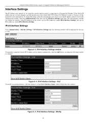
...click the Interface Settings menu link. Add To modify an existing Interface, click that interface's hyperlinked Interface Name, which will be set using the web manager users must access the IP Address menu located in the Administration folder. xStack DGS-3400 Series Layer 2 Gigabit ...IPv4 Interface Settings Click Administration > Interface Settings > IPv4 Interface Settings link, the following window to Section 4 of the xStack DGS-3400 Series CLI Manual or return to configure. To change IP settings using the console interface prior to connecting to setup IP interfaces on the switch,...
...click the Interface Settings menu link. Add To modify an existing Interface, click that interface's hyperlinked Interface Name, which will be set using the web manager users must access the IP Address menu located in the Administration folder. xStack DGS-3400 Series Layer 2 Gigabit ...IPv4 Interface Settings Click Administration > Interface Settings > IPv4 Interface Settings link, the following window to Section 4 of the xStack DGS-3400 Series CLI Manual or return to configure. To change IP settings using the console interface prior to connecting to setup IP interfaces on the switch,...
User Manual
Page 60
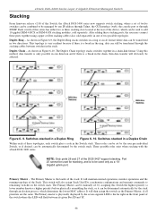
...user per individual Switch, or if desired, can be automatically determined by one IP address through Telnet, the GUI interface (web), the console port or through the stacking cables between its given Box ID and 'H'. 46 Port 25 cannot be used for stacking, and is ..., synchronize configurations and transmit commands to remaining switches in two directions. Switches stacked in a chain-link format. Three possible roles exist when stacking with the xStack DGS-3400 series. xStack DGS-3400 Series Layer 2 Gigabit Ethernet Managed Switch Stacking From firmware release v2.00 of this Switch,...
...user per individual Switch, or if desired, can be automatically determined by one IP address through Telnet, the GUI interface (web), the console port or through the stacking cables between its given Box ID and 'H'. 46 Port 25 cannot be used for stacking, and is ..., synchronize configurations and transmit commands to remaining switches in two directions. Switches stacked in a chain-link format. Three possible roles exist when stacking with the xStack DGS-3400 series. xStack DGS-3400 Series Layer 2 Gigabit Ethernet Managed Switch Stacking From firmware release v2.00 of this Switch,...
User Manual
Page 62
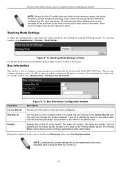
... applications of the switch stack. The lower the number, the higher the priority. Users must first enable this screen is found in the xStack DGS-3400 Series. Parameter Current Box ID Figure 6- 12. The user may configure parameters such as box ID, box priority and pre-assigning model ...Settings. The Primary Master switch will be configured. Priority Displays the priority ID of each device in the stack to be produced on the local console port of the Switch. Users can only get device information, configure Box IDs, save it using the following window. The box (switch) with...
... applications of the switch stack. The lower the number, the higher the priority. Users must first enable this screen is found in the xStack DGS-3400 Series. Parameter Current Box ID Figure 6- 12. The user may configure parameters such as box ID, box priority and pre-assigning model ...Settings. The Primary Master switch will be configured. Priority Displays the priority ID of each device in the stack to be produced on the local console port of the Switch. Users can only get device information, configure Box IDs, save it using the following window. The box (switch) with...
