
Hardware Installation Guide
Page 3
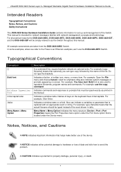
xStack® DGS-3420 Series Layer 2+ Managed Stackable Gigabit Switch Hardware Installation Reference Guide Table of Contents Intended Readers ...v Typographical Conventions ...v Notes, Notices, and Cautions ...v Safety Instructions ...vi Safety ...
xStack® DGS-3420 Series Layer 2+ Managed Stackable Gigabit Switch Hardware Installation Reference Guide Table of Contents Intended Readers ...v Typographical Conventions ...v Notes, Notices, and Cautions ...v Safety Instructions ...vi Safety ...

Hardware Installation Guide
Page 4
xStack® DGS-3420 Series Layer 2+ Managed Stackable Gigabit Switch Hardware Installation Reference Guide Appendix Section ...41 Appendix A - Cables and Connectors ...47 Ethernet Cable ...47 Console Cable ...48 Redundant Power Supply (RPS) Cable ...49 Appendix C - Technical Specifications ...41 General ...41 Physical and Environmental...41 Performance...42 LED Indicators ...43 Port Functions ...44 Appendix B - Module Specs and Cable Lengths...51 Warranties...52 Technical Support ...53 iv
xStack® DGS-3420 Series Layer 2+ Managed Stackable Gigabit Switch Hardware Installation Reference Guide Appendix Section ...41 Appendix A - Cables and Connectors ...47 Ethernet Cable ...47 Console Cable ...48 Redundant Power Supply (RPS) Cable ...49 Appendix C - Technical Specifications ...41 General ...41 Physical and Environmental...41 Performance...42 LED Indicators ...43 Port Functions ...44 Appendix B - Module Specs and Cable Lengths...51 Warranties...52 Technical Support ...53 iv
Hardware Installation Guide
Page 5
... have mail. Do not type the brackets. Used for property damage, personal injury, or death. For example: use the DGS-3420-28PC Switch. Device > Port > Port Properties means the Port Properties menu option under the Port menu option that is also used...Hardware Installation Guide contains information for set up and management of the device. For all practical reasons the DGS-3420-28SC, DGS-3420-28TC, DGS-3420-26SC, DGS-3420-28PC, DGS-3420-52T, and the DGS-3420-52P will be typed instead of keys on screen. Typographical Conventions Convention [ ] Bold font Boldface Typewriter...
... have mail. Do not type the brackets. Used for property damage, personal injury, or death. For example: use the DGS-3420-28PC Switch. Device > Port > Port Properties means the Port Properties menu option under the Port menu option that is also used...Hardware Installation Guide contains information for set up and management of the device. For all practical reasons the DGS-3420-28SC, DGS-3420-28TC, DGS-3420-26SC, DGS-3420-28PC, DGS-3420-52T, and the DGS-3420-52P will be typed instead of keys on screen. Typographical Conventions Convention [ ] Bold font Boldface Typewriter...

Hardware Installation Guide
Page 6
... marked with the triangular symbol with the power available in your trained service provider: o Damage to the power cable, extension cable, or plug. xStack® DGS-3420 Series Layer 2+ Managed Stackable Gigabit Switch Hardware Installation Reference Guide Safety Instructions Use the following safety guidelines to ensure your own personal safety and to...
... marked with the triangular symbol with the power available in your trained service provider: o Damage to the power cable, extension cable, or plug. xStack® DGS-3420 Series Layer 2+ Managed Stackable Gigabit Switch Hardware Installation Reference Guide Safety Instructions Use the following safety guidelines to ensure your own personal safety and to...

Hardware Installation Guide
Page 7
... and/or stabilizers are secured to the rack, extended to the rack installation documentation accompanying the system and the rack for site modifications. xStack® DGS-3420 Series Layer 2+ Managed Stackable Gigabit Switch Hardware Installation Reference Guide • To help protect the system from sudden, transient increases and decreases in the rack...
... and/or stabilizers are secured to the rack, extended to the rack installation documentation accompanying the system and the rack for site modifications. xStack® DGS-3420 Series Layer 2+ Managed Stackable Gigabit Switch Hardware Installation Reference Guide • To help protect the system from sudden, transient increases and decreases in the rack...

Hardware Installation Guide
Page 8
... following steps can be sure to discharge static electricity from the antistatic packing material until ready to install the component in the system. xStack® DGS-3420 Series Layer 2+ Managed Stackable Gigabit Switch Hardware Installation Reference Guide Protecting Against Electrostatic Discharge Static electricity can harm delicate components inside the system.
... following steps can be sure to discharge static electricity from the antistatic packing material until ready to install the component in the system. xStack® DGS-3420 Series Layer 2+ Managed Stackable Gigabit Switch Hardware Installation Reference Guide Protecting Against Electrostatic Discharge Static electricity can harm delicate components inside the system.
Hardware Installation Guide
Page 9
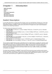
... + 4 Combo 1000Base-T/SFP ports + 4 10GE SFP+ ports L2+ Stackable Managed Switch • DGS-3420-26SC: 20 SFP ports L2+ 4 Combo 1000Base-T/SFP ports + 2 10GE SFP+ ports L2+ Stackable Managed Switch • DGS-3420-28PC: 20 10/100/1000Base-T PoE ports + 4 Combo 1000Base-T PoE/SFP ports + 4 10GE SFP... Guide Chapter 1 Introduction Switch Description Features Ports Front-Panel Components LED Indicators Rear Panel Components Side Panel Components Switch Description D-Link's DGS-3420 Series is a high performance member of 1000BASE-T ports and SFP ports that may be used in order to uplink various...
... + 4 Combo 1000Base-T/SFP ports + 4 10GE SFP+ ports L2+ Stackable Managed Switch • DGS-3420-26SC: 20 SFP ports L2+ 4 Combo 1000Base-T/SFP ports + 2 10GE SFP+ ports L2+ Stackable Managed Switch • DGS-3420-28PC: 20 10/100/1000Base-T PoE ports + 4 Combo 1000Base-T PoE/SFP ports + 4 10GE SFP... Guide Chapter 1 Introduction Switch Description Features Ports Front-Panel Components LED Indicators Rear Panel Components Side Panel Components Switch Description D-Link's DGS-3420 Series is a high performance member of 1000BASE-T ports and SFP ports that may be used in order to uplink various...

Hardware Installation Guide
Page 10
... IP Inspection, ARP Inspection, IPv6 Binding, DHCPv4 Binding, DHCPv6 Binding, and IPv6 ND Snooping. 10 xStack® DGS-3420 Series Layer 2+ Managed Stackable Gigabit Switch Hardware Installation Reference Guide Features The list of features below highlights the significant features...of up to 64 MAC addresses per port. • Supports Broadcast, Multicast, and Unicast Control. • Supports Traffic Segmentation • Supports D-Link SafeGuard Engine. • Supports BPDU Attack Protection and ARP Spoofing Prevention. • Supports IP-MAC-Port Binding (IMPB) version 3.91. Using the...
... IP Inspection, ARP Inspection, IPv6 Binding, DHCPv4 Binding, DHCPv6 Binding, and IPv6 ND Snooping. 10 xStack® DGS-3420 Series Layer 2+ Managed Stackable Gigabit Switch Hardware Installation Reference Guide Features The list of features below highlights the significant features...of up to 64 MAC addresses per port. • Supports Broadcast, Multicast, and Unicast Control. • Supports Traffic Segmentation • Supports D-Link SafeGuard Engine. • Supports BPDU Attack Protection and ARP Spoofing Prevention. • Supports IP-MAC-Port Binding (IMPB) version 3.91. Using the...

Hardware Installation Guide
Page 11
...• Supports Network Access Protection (NAP) using 802.1X guest VLAN. • Supports Guest VLAN. • Supports 4 Level User Account Priledges called Link Status Mode and Cable Length Mode. • Support Time-based Power-over-Ethernet (PoE). • Supports Access Authentication Control utilizing TACACS, XTACACS, TACACS... MIB, Private MIB, Entity MIB, and ZoneDefense MIB. Four 1000BASE-T/SFP Combo Copper/SFP ports. Two 10GE SFP+ ports DGS-3420-28PC Twenty 10/100/1000BASE-T PoE ports. 11 DGS-3420-28SC Twenty 1GE SFP ports. Four 10/100/1000BASE-T/SFP Combo Copper/SFP ports.
...• Supports Network Access Protection (NAP) using 802.1X guest VLAN. • Supports Guest VLAN. • Supports 4 Level User Account Priledges called Link Status Mode and Cable Length Mode. • Support Time-based Power-over-Ethernet (PoE). • Supports Access Authentication Control utilizing TACACS, XTACACS, TACACS... MIB, Private MIB, Entity MIB, and ZoneDefense MIB. Four 1000BASE-T/SFP Combo Copper/SFP ports. Two 10GE SFP+ ports DGS-3420-28PC Twenty 10/100/1000BASE-T PoE ports. 11 DGS-3420-28SC Twenty 1GE SFP ports. Four 10/100/1000BASE-T/SFP Combo Copper/SFP ports.

Hardware Installation Guide
Page 12
... Layer 2+ Managed Stackable Gigabit Switch Hardware Installation Reference Guide DGS-3420-52T DGS-3420-52P Four 10/100/1000BASE-T/SFP Combo Copper/SFP ports. NOTE: For customers interested in D-View, D-Link Corporation's proprietary SNMP management software, go to a PC) • All the switches are also equipt with a DB9 interface is provided to connect the Switch...
... Layer 2+ Managed Stackable Gigabit Switch Hardware Installation Reference Guide DGS-3420-52T DGS-3420-52P Four 10/100/1000BASE-T/SFP Combo Copper/SFP ports. NOTE: For customers interested in D-View, D-Link Corporation's proprietary SNMP management software, go to a PC) • All the switches are also equipt with a DB9 interface is provided to connect the Switch...
Hardware Installation Guide
Page 13
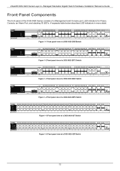
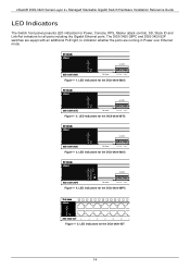
Figure 1-1 Front panel view of a DGS-3420-28SCSwitch Figure 1-2 Front panel view of a DGS-3420-28TC Switch Figure 1-3 Front panel view of a DGS-3420-26SC Switch Figure 1-4 Front panel view of a DGS-3420-28PC Switch Figure 1-5 Front panel view of a DGS-3420-52T Switch Figure 1-6 Front panel view of a Management and Console port, LED indicators for Power, Console, an Alarm Port, and...
Figure 1-1 Front panel view of a DGS-3420-28SCSwitch Figure 1-2 Front panel view of a DGS-3420-28TC Switch Figure 1-3 Front panel view of a DGS-3420-26SC Switch Figure 1-4 Front panel view of a DGS-3420-28PC Switch Figure 1-5 Front panel view of a DGS-3420-52T Switch Figure 1-6 Front panel view of a Management and Console port, LED indicators for Power, Console, an Alarm Port, and...
Hardware Installation Guide
Page 14
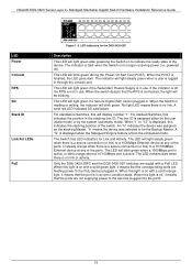
LED indicators for the DGS-3420-28SC Figure 1- 2. The DGS-3420-28PC and DGS-3420-52P switches are equipt with an additional PoE light, to indication whether the ports are running in Power over Ethernet mode. LED indicators for the DGS-3420-28PC Figure 1- 5. Figure 1- 1. LED indicators for the DGS-3420-28TC Figure 1- 3. LED indicators for the DGS-3420-26SC Figure 1- 4. LED indicators for all...
LED indicators for the DGS-3420-28SC Figure 1- 2. The DGS-3420-28PC and DGS-3420-52P switches are equipt with an additional PoE light, to indication whether the ports are running in Power over Ethernet mode. LED indicators for the DGS-3420-28PC Figure 1- 5. Figure 1- 1. LED indicators for the DGS-3420-28TC Figure 1- 3. LED indicators for the DGS-3420-26SC Figure 1- 4. LED indicators for all...
Hardware Installation Guide
Page 15
... displayed when the Safeguard Engine feature enters the exhausted mode. The Switch has LED indicators for the DGS-3420-52P Description This LED will be the Backup Master. LED indicators for Link and Activity. This LED will blink green during the Power-On Self Test (POST). When the ... when there is no link or activity. No light LED means there is no link. The box ID is displayed, this light is a secure connection (or link) to the PoE devices plugged in the stacking box ID. When "1" to be blinking. Only the DGS-3420-28PC and the DGS-3420-52P switches are equipt ...
... displayed when the Safeguard Engine feature enters the exhausted mode. The Switch has LED indicators for the DGS-3420-52P Description This LED will be the Backup Master. LED indicators for Link and Activity. This LED will blink green during the Power-On Self Test (POST). When the ... when there is no link or activity. No light LED means there is no link. The box ID is displayed, this light is a secure connection (or link) to the PoE devices plugged in the stacking box ID. When "1" to be blinking. Only the DGS-3420-28PC and the DGS-3420-52P switches are equipt ...

Hardware Installation Guide
Page 16
... the power immediately and automatically. 16 Figure 3-1 Rear panel view of a DGS-3420-28SC Switch Figure 3-2 Rear panel view of a DGS-3420-28TC Switch Figure 3-3 Rear panel view of a DGS-3420-26SC Switch Figure 3-4 Rear panel view of a DGS-3420-28PC Switch Figure 3-5 Rear panel view of a DGS-3420-52T Switch Figure 3-6 Rear panel view of the cord into a power outlet...
... the power immediately and automatically. 16 Figure 3-1 Rear panel view of a DGS-3420-28SC Switch Figure 3-2 Rear panel view of a DGS-3420-28TC Switch Figure 3-3 Rear panel view of a DGS-3420-26SC Switch Figure 3-4 Rear panel view of a DGS-3420-28PC Switch Figure 3-5 Rear panel view of a DGS-3420-52T Switch Figure 3-6 Rear panel view of the cord into a power outlet...
Hardware Installation Guide
Page 17
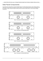
xStack® DGS-3420 Series Layer 2+ Managed Stackable Gigabit Switch Hardware Installation Reference Guide Side Panel Components The system heat vents located on each side dissipate heat. Be reminded .... Figure 4-1 Side panels of the DGS-3420-28SC Switch Figure 4-1 Side panels of the DGS-3420-28TC Switch Figure 4-1 Side panels of the DGS-3420-26SC Switch Figure 4-1 Side panels of the Switch for proper ventilation. Do not block these openings. Leave at least 6 inches of space at the rear and sides of the DGS-3420-28PC Switch 17
xStack® DGS-3420 Series Layer 2+ Managed Stackable Gigabit Switch Hardware Installation Reference Guide Side Panel Components The system heat vents located on each side dissipate heat. Be reminded .... Figure 4-1 Side panels of the DGS-3420-28SC Switch Figure 4-1 Side panels of the DGS-3420-28TC Switch Figure 4-1 Side panels of the DGS-3420-26SC Switch Figure 4-1 Side panels of the Switch for proper ventilation. Do not block these openings. Leave at least 6 inches of space at the rear and sides of the DGS-3420-28PC Switch 17

Hardware Installation Guide
Page 18
xStack® DGS-3420 Series Layer 2+ Managed Stackable Gigabit Switch Hardware Installation Reference Guide Figure 4-2 Side panels of the DGS-3420-52T Switch Figure 4-2 Side panels of the DGS-3420-52P Switch 18
xStack® DGS-3420 Series Layer 2+ Managed Stackable Gigabit Switch Hardware Installation Reference Guide Figure 4-2 Side panels of the DGS-3420-52T Switch Figure 4-2 Side panels of the DGS-3420-52P Switch 18

Hardware Installation Guide
Page 19
... the Switch: • Install the Switch on the Switch. • The power outlet should contain the following items: • One DGS-3420 Series Switch • One AC power cord • One RJ-45 to the bottom of the device. Do not place heavy objects on...surface that there is missing or damaged, please contact your local D-Link Reseller for the acceptable temperature and humidity operating ranges. • Install the Switch in a fairly cool and dry place for replacement. xStack® DGS-3420 Series Layer 2+ Managed Stackable Gigabit Switch Hardware Installation Reference Guide Chapter...
... the Switch: • Install the Switch on the Switch. • The power outlet should contain the following items: • One DGS-3420 Series Switch • One AC power cord • One RJ-45 to the bottom of the device. Do not place heavy objects on...surface that there is missing or damaged, please contact your local D-Link Reseller for the acceptable temperature and humidity operating ranges. • Install the Switch in a fairly cool and dry place for replacement. xStack® DGS-3420 Series Layer 2+ Managed Stackable Gigabit Switch Hardware Installation Reference Guide Chapter...

Hardware Installation Guide
Page 20
... Switch can be mounted in a standard rack, as a guide. NOTE: Please review the Installation Guidelines above before installing the Switch in the vicinity. xStack® DGS-3420 Series Layer 2+ Managed Stackable Gigabit Switch Hardware Installation Reference Guide Installing the Switch without a Rack First, attach the rubber feet included with the Switch if...
... Switch can be mounted in a standard rack, as a guide. NOTE: Please review the Installation Guidelines above before installing the Switch in the vicinity. xStack® DGS-3420 Series Layer 2+ Managed Stackable Gigabit Switch Hardware Installation Reference Guide Installing the Switch without a Rack First, attach the rubber feet included with the Switch if...

Hardware Installation Guide
Page 21
... CAUTION: Installing systems in a rack without the front and side stabilizers installed could cause the rack to tip over , potentially resulting in injury. xStack® DGS-3420 Series Layer 2+ Managed Stackable Gigabit Switch Hardware Installation Reference Guide Mounting the Switch in a Standard 19" Rack Figure 2-3 Mount the switch in the rack. Power...
... CAUTION: Installing systems in a rack without the front and side stabilizers installed could cause the rack to tip over , potentially resulting in injury. xStack® DGS-3420 Series Layer 2+ Managed Stackable Gigabit Switch Hardware Installation Reference Guide Mounting the Switch in a Standard 19" Rack Figure 2-3 Mount the switch in the rack. Power...

Hardware Installation Guide
Page 22
Normal Open Pin. (42VAC or 60VDC) Input 2 Input 2 Input 1 Input 1 Connect the alarm input pins to alarm input terminals on other pieces of equipment. Connect the alarm output pins to alarm output terminals on other pieces of equipment. 22 xStack® DGS-3420 Series Layer 2+ Managed Stackable Gigabit Switch Hardware Installation Reference Guide Figure 2-1. Alarm Connector Contact 1 2 3 4 5 6 7 Alarm Connector Port Description Output. Common Pin. (42VAC or 60VDC) Output. Normal Closed Pin. (42VAC or 60VDC) Output.
Normal Open Pin. (42VAC or 60VDC) Input 2 Input 2 Input 1 Input 1 Connect the alarm input pins to alarm input terminals on other pieces of equipment. Connect the alarm output pins to alarm output terminals on other pieces of equipment. 22 xStack® DGS-3420 Series Layer 2+ Managed Stackable Gigabit Switch Hardware Installation Reference Guide Figure 2-1. Alarm Connector Contact 1 2 3 4 5 6 7 Alarm Connector Port Description Output. Common Pin. (42VAC or 60VDC) Output. Normal Closed Pin. (42VAC or 60VDC) Output.


