
Hardware Installation Guide
Page 3
xStack® DGS-3420 Series Layer 2+ Managed Stackable Gigabit Switch Hardware Installation Reference Guide Table of Contents Intended Readers ...v Typographical Conventions ...v Notes, Notices, and Cautions ...v Safety Instructions ...vi Safety Cautions...vi General Precautions for Rack-Mountable Products vii Protecting Against Electrostatic Discharge...viii Chapter 1 Introduction...9 Switch Description ...9 Features...10 Ports ...11 Front-Panel Components ...13 LED Indicators ...14 Rear Panel Components ...16 Side Panel Components...17 Chapter 2 Installation...19...
xStack® DGS-3420 Series Layer 2+ Managed Stackable Gigabit Switch Hardware Installation Reference Guide Table of Contents Intended Readers ...v Typographical Conventions ...v Notes, Notices, and Cautions ...v Safety Instructions ...vi Safety Cautions...vi General Precautions for Rack-Mountable Products vii Protecting Against Electrostatic Discharge...viii Chapter 1 Introduction...9 Switch Description ...9 Features...10 Ports ...11 Front-Panel Components ...13 LED Indicators ...14 Rear Panel Components ...16 Side Panel Components...17 Chapter 2 Installation...19...
Hardware Installation Guide
Page 5
... Switch throughout this manual. A CAUTION indicates a potential for emphasis. For all practical reasons the DGS-3420-28SC, DGS-3420-28TC, DGS-3420-26SC, DGS-3420-28PC, DGS-3420-52T, and the DGS-3420-52P will be typed instead of the file. Menu Name > Menu Option Indicates the menu structure. xStack® DGS-3420 Series Layer 2+ Managed Stackable Gigabit Switch Hardware Installation Reference Guide Intended Readers Typographical Conventions Notes, Notices, and Cautions Safety Instructions The DGS-3420 Series Hardware Installation Guide contains information for set up and management...
... Switch throughout this manual. A CAUTION indicates a potential for emphasis. For all practical reasons the DGS-3420-28SC, DGS-3420-28TC, DGS-3420-26SC, DGS-3420-28PC, DGS-3420-52T, and the DGS-3420-52P will be typed instead of the file. Menu Name > Menu Option Indicates the menu structure. xStack® DGS-3420 Series Layer 2+ Managed Stackable Gigabit Switch Hardware Installation Reference Guide Intended Readers Typographical Conventions Notes, Notices, and Cautions Safety Instructions The DGS-3420 Series Hardware Installation Guide contains information for set up and management...
Hardware Installation Guide
Page 9
...) combo ports are used in full-duplex mode. A unique D-Link Safeguard Engine protects the DGS-3420 Series from the threat of worms and viruses, thereby increasing overall reliability, serviceability, and availability The Switch has a combination of 1000BASE-T ports and SFP ports that may be used with a user-friendly management interface for the networking professional. The dedicated stacking ports offer up to high speed Gigabit connections. The Series features the following list of the D-Link xStack®...
...) combo ports are used in full-duplex mode. A unique D-Link Safeguard Engine protects the DGS-3420 Series from the threat of worms and viruses, thereby increasing overall reliability, serviceability, and availability The Switch has a combination of 1000BASE-T ports and SFP ports that may be used with a user-friendly management interface for the networking professional. The dedicated stacking ports offer up to high speed Gigabit connections. The Series features the following list of the D-Link xStack®...

Hardware Installation Guide
Page 10
...; Supports Access Control List (ACL) with Ingress ACL, Egress ACL, Time-based ACL, ACL Statistics, and CPU Interface Filtering. • Supports Secure Shell (SSHv2) with IPv4/IPv6 access. • Supports Secure Sockets Layer (SSL) versions 1, 2, and 3 with IPv4/IPv6 access. • Supports Port Security of the Switch. • Supports Virtual Stacking. This feature includes IP Inspection, ARP Inspection, IPv6 Binding, DHCPv4 Binding, DHCPv6 Binding, and IPv6 ND Snooping. 10 xStack® DGS-3420 Series Layer 2+ Managed Stackable Gigabit Switch Hardware Installation Reference Guide Features...
...; Supports Access Control List (ACL) with Ingress ACL, Egress ACL, Time-based ACL, ACL Statistics, and CPU Interface Filtering. • Supports Secure Shell (SSHv2) with IPv4/IPv6 access. • Supports Secure Sockets Layer (SSL) versions 1, 2, and 3 with IPv4/IPv6 access. • Supports Port Security of the Switch. • Supports Virtual Stacking. This feature includes IP Inspection, ARP Inspection, IPv6 Binding, DHCPv4 Binding, DHCPv6 Binding, and IPv6 ND Snooping. 10 xStack® DGS-3420 Series Layer 2+ Managed Stackable Gigabit Switch Hardware Installation Reference Guide Features...

Hardware Installation Guide
Page 11
... called Link Status Mode and Cable Length Mode. • Support Time-based Power-over-Ethernet (PoE). • Supports Access Authentication Control utilizing TACACS, XTACACS, TACACS+, and RADIUS protocols • Supports MIBs like MIBII, Bridge MIB, SNMPv2 MIB, RMON MIB, RMONv2 MIB, Ether-like the Command Line Interface (CLI), Web-based Graphical User Interface (Web-based GUI), and more. • Supports Telnet Server and Client from IPv4 and IPv6. • Supports Trivial File Transfer Protocol (TFTP) Client. • Supports Simple Network Management Protocol (SNMP) version...
... called Link Status Mode and Cable Length Mode. • Support Time-based Power-over-Ethernet (PoE). • Supports Access Authentication Control utilizing TACACS, XTACACS, TACACS+, and RADIUS protocols • Supports MIBs like MIBII, Bridge MIB, SNMPv2 MIB, RMON MIB, RMONv2 MIB, Ether-like the Command Line Interface (CLI), Web-based Graphical User Interface (Web-based GUI), and more. • Supports Telnet Server and Client from IPv4 and IPv6. • Supports Trivial File Transfer Protocol (TFTP) Client. • Supports Simple Network Management Protocol (SNMP) version...
Hardware Installation Guide
Page 14
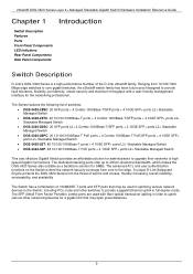
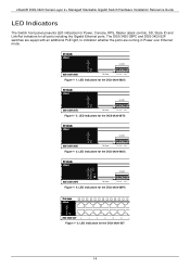
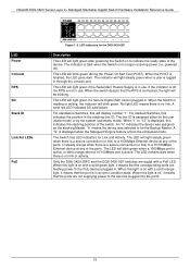
...the DGS-3420-28SC Figure 1- 2. LED indicators for the DGS-3420-52T 14 xStack® DGS-3420 Series Layer 2+ Managed Stackable Gigabit Switch Hardware Installation Reference Guide LED Indicators The Switch front panel presents LED indicators for Power, Console, RPS, Master (stack control), SD, Stack ID and Link/Act indicators for the DGS-3420-28PC Figure 1- 5. LED indicators for all ports including the Gigabit Ethernet ports. The DGS-3420-28PC and DGS-3420-52P switches are equipt with an additional PoE light, to indication whether the ports are running in Power over Ethernet mode.
...the DGS-3420-28SC Figure 1- 2. LED indicators for the DGS-3420-52T 14 xStack® DGS-3420 Series Layer 2+ Managed Stackable Gigabit Switch Hardware Installation Reference Guide LED Indicators The Switch front panel presents LED indicators for Power, Console, RPS, Master (stack control), SD, Stack ID and Link/Act indicators for the DGS-3420-28PC Figure 1- 5. LED indicators for all ports including the Gigabit Ethernet ports. The DGS-3420-28PC and DGS-3420-52P switches are equipt with an additional PoE light, to indication whether the ports are running in Power over Ethernet mode.
Hardware Installation Guide
Page 15
... the user (static mode) or by the system (automatic mode). This LED will be the Backup Master. For standalone Switches, this light is finished, the LED goes dark. When "1" to a 10/100Mbps Ethernet device at any of the device. The Switch has LED indicators for the DGS-3420-52P Description This LED will blink green. xStack® DGS-3420 Series Layer 2+ Managed Stackable Gigabit Switch Hardware Installation Reference Guide LED Power Console RPS SD Stack ID Link/Act LEDs PoE Figure 1- 6. This LED will display number "1". If...
... the user (static mode) or by the system (automatic mode). This LED will be the Backup Master. For standalone Switches, this light is finished, the LED goes dark. When "1" to a 10/100Mbps Ethernet device at any of the device. The Switch has LED indicators for the DGS-3420-52P Description This LED will blink green. xStack® DGS-3420 Series Layer 2+ Managed Stackable Gigabit Switch Hardware Installation Reference Guide LED Power Console RPS SD Stack ID Link/Act LEDs PoE Figure 1- 6. This LED will display number "1". If...

Hardware Installation Guide
Page 19
... kit for CLI reference guide/Web UI reference guide/Hardware Installation Guide/D-View module If any item is missing or damaged, please contact your local D-Link Reseller for replacement. This is without PoE functionality) of the device. Leave at least 10 cm (4 inches) of space at least 6.6 lb. (3kg - xStack® DGS-3420 Series Layer 2+ Managed Stackable Gigabit Switch Hardware Installation Reference Guide Chapter 2 Installation Package Contents Installation Guidelines Power On (AC Power) Alarm Connector Installing SFP and SFP+ Ports Connecting to a Redundant Power Supply External...
... kit for CLI reference guide/Web UI reference guide/Hardware Installation Guide/D-View module If any item is missing or damaged, please contact your local D-Link Reseller for replacement. This is without PoE functionality) of the device. Leave at least 10 cm (4 inches) of space at least 6.6 lb. (3kg - xStack® DGS-3420 Series Layer 2+ Managed Stackable Gigabit Switch Hardware Installation Reference Guide Chapter 2 Installation Package Contents Installation Guidelines Power On (AC Power) Alarm Connector Installing SFP and SFP+ Ports Connecting to a Redundant Power Supply External...
Hardware Installation Guide
Page 25
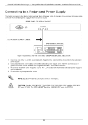
...and 52T) 1. xStack® DGS-3420 Series Layer 2+ Managed Stackable Gigabit Switch Hardware Installation Reference Guide Connecting to a Redundant Power Supply The Switch connects to the main power source. NOTE: See the DPS-500 documentation for more information. The DGS-3420-28PC and the DGS-3420-52P uses the DPS700. 25 A standard, three-pronged AC power cable connects the redundant power supply to the Master Switch using a 14-pin DC power cable. Using a standard AC power cable, connect the redundant power supply to indicate a successful connection. 3. A green LED on the front of...
...and 52T) 1. xStack® DGS-3420 Series Layer 2+ Managed Stackable Gigabit Switch Hardware Installation Reference Guide Connecting to a Redundant Power Supply The Switch connects to the main power source. NOTE: See the DPS-500 documentation for more information. The DGS-3420-28PC and the DGS-3420-52P uses the DPS700. 25 A standard, three-pronged AC power cable connects the redundant power supply to the Master Switch using a 14-pin DC power cable. Using a standard AC power cable, connect the redundant power supply to indicate a successful connection. 3. A green LED on the front of...

Hardware Installation Guide
Page 29
...; DGS-3420 Series Layer 2+ Managed Stackable Gigabit Switch Hardware Installation Reference Guide Chapter 3 Connecting the Switch Switch to End Node Switch to Switch Connecting To Network Backbone or Server Switch to an end node NOTE: All high-performance N-Way Ethernet ports can support both MDI-II and MDI-X connections. The Link/Act LEDs for more information. 29 Figure 3-1 Connect a DGS-3420 Series Switch to End Node End nodes include PCs outfitted with a 10/100/1000 Mbps RJ-45 Ethernet Network Interface Card (NIC) and routers. Switch...
...; DGS-3420 Series Layer 2+ Managed Stackable Gigabit Switch Hardware Installation Reference Guide Chapter 3 Connecting the Switch Switch to End Node Switch to Switch Connecting To Network Backbone or Server Switch to an end node NOTE: All high-performance N-Way Ethernet ports can support both MDI-II and MDI-X connections. The Link/Act LEDs for more information. 29 Figure 3-1 Connect a DGS-3420 Series Switch to End Node End nodes include PCs outfitted with a 10/100/1000 Mbps RJ-45 Ethernet Network Interface Card (NIC) and routers. Switch...

Hardware Installation Guide
Page 30
...; DGS-3420 Series Layer 2+ Managed Stackable Gigabit Switch Hardware Installation Reference Guide Figure 3-2 Connect the Switch to a port on the type of 10/100/1000Mbps in full duplex mode. The Link LED turns green when a connection is made. You can operate at a speed of port. The fiber-optic ports can connect to the Gigabit Ethernet ports using a fiber-optic cable or a Category 5E copper cable, depending on a switch with a straight or crossover cable Connect to a Network Backbone or Server The combo SFP ports and the 1000BASE-T ports are ideal for uplinking to a server 30...
...; DGS-3420 Series Layer 2+ Managed Stackable Gigabit Switch Hardware Installation Reference Guide Figure 3-2 Connect the Switch to a port on the type of 10/100/1000Mbps in full duplex mode. The Link LED turns green when a connection is made. You can operate at a speed of port. The fiber-optic ports can connect to the Gigabit Ethernet ports using a fiber-optic cable or a Category 5E copper cable, depending on a switch with a straight or crossover cable Connect to a Network Backbone or Server The combo SFP ports and the 1000BASE-T ports are ideal for uplinking to a server 30...

Hardware Installation Guide
Page 31
... The user can configure the Switch, monitor the LED panel, and display statistics graphically using Telnet. xStack® DGS-3420 Series Layer 2+ Managed Stackable Gigabit Switch Hardware Installation Reference Guide Chapter 4 Introduction to Switch Management Management Options Connecting the Console Port Connecting to the Switch for example) to establish the physical connection. The user may be included with MIB objects stored in -band using a Web browser, such as follows: • Select the appropriate serial port (COM port 1 or COM port 2). • Set the data rate to...
... The user can configure the Switch, monitor the LED panel, and display statistics graphically using Telnet. xStack® DGS-3420 Series Layer 2+ Managed Stackable Gigabit Switch Hardware Installation Reference Guide Chapter 4 Introduction to Switch Management Management Options Connecting the Console Port Connecting to the Switch for example) to establish the physical connection. The user may be included with MIB objects stored in -band using a Web browser, such as follows: • Select the appropriate serial port (COM port 1 or COM port 2). • Set the data rate to...

Hardware Installation Guide
Page 32
... configure the Switch. • Enter the commands to perform all commands and additional information on Windows 2000 service packs. • After you have been previously set to VT-100. Click Properties from the drop-down menu 3. The administrator must first create user names and passwords. See the DGS-3420 Series CLI Reference Guide on the documentation CD for more information on setting up the terminal, plug the power cable into the command line interface (CLI...
... configure the Switch. • Enter the commands to perform all commands and additional information on Windows 2000 service packs. • After you have been previously set to VT-100. Click Properties from the drop-down menu 3. The administrator must first create user names and passwords. See the DGS-3420 Series CLI Reference Guide on the documentation CD for more information on setting up the terminal, plug the power cable into the command line interface (CLI...

Hardware Installation Guide
Page 33
... be created for the out-of 255.255.255.0. The default IP address of the Management port is 192.168.0.1, and a subnet mask of -band Management port in the web interface, use the command: show out_band_ipif To change settings for the Switch. To change the configuration of the Management port, use the command: config out_band_ipif {ipaddress | state [enable | disable] | gateway } To view the status or IP settings, use the following screen appears: UserName: DGS-3420-28SC Gigabit Ethernet Switch Command Line Interface Firmware: Build 1.00.017 Copyright(C) 2011 D-Link...
... be created for the out-of 255.255.255.0. The default IP address of the Management port is 192.168.0.1, and a subnet mask of -band Management port in the web interface, use the command: show out_band_ipif To change settings for the Switch. To change the configuration of the Management port, use the command: config out_band_ipif {ipaddress | state [enable | disable] | gateway } To view the status or IP settings, use the following screen appears: UserName: DGS-3420-28SC Gigabit Ethernet Switch Command Line Interface Firmware: Build 1.00.017 Copyright(C) 2011 D-Link...

Hardware Installation Guide
Page 34
... CLI login prompt, enter create account admin followed by the and press the Enter key. 2. Once entered, the Switch will then prompt the user to the Switch's management software. The sample below . 34 After the initial login, define new passwords for both default user names to prevent unauthorized access to the startup configuration. Assigning IP Addresses Each Switch must use the save all your networking address scheme. Logging in length. xStack® DGS-3420 Series Layer 2+ Managed Stackable Gigabit Switch Hardware Installation Reference Guide Password...
... CLI login prompt, enter create account admin followed by the and press the Enter key. 2. Once entered, the Switch will then prompt the user to the Switch's management software. The sample below . 34 After the initial login, define new passwords for both default user names to prevent unauthorized access to the startup configuration. Assigning IP Addresses Each Switch must use the save all your networking address scheme. Logging in length. xStack® DGS-3420 Series Layer 2+ Managed Stackable Gigabit Switch Hardware Installation Reference Guide Password...

Hardware Installation Guide
Page 35
... must be set using the Command Line Interface (CLI) over the console serial port as follows: Starting at the command line prompt, enter the commands config ipif System ipaddress xxx.xxx.xxx.xxx/yyy.yyy.yyy.yyy Where the x's represent the IP address to be used to connect a management station to be managed with the Web-based manager. xStack® DGS-3420 Series Layer 2+ Managed Stackable Gigabit Switch Hardware Installation Reference Guide DGS-3420-28SC:admin# show switch Command: show switch Device Type : DGS-3420-28SC Gigabit Ethernet Switch Unit ID : 1 MAC Address : 00-01...
... must be set using the Command Line Interface (CLI) over the console serial port as follows: Starting at the command line prompt, enter the commands config ipif System ipaddress xxx.xxx.xxx.xxx/yyy.yyy.yyy.yyy Where the x's represent the IP address to be used to connect a management station to be managed with the Web-based manager. xStack® DGS-3420 Series Layer 2+ Managed Stackable Gigabit Switch Hardware Installation Reference Guide DGS-3420-28SC:admin# show switch Command: show switch Device Type : DGS-3420-28SC Gigabit Ethernet Switch Unit ID : 1 MAC Address : 00-01...

Hardware Installation Guide
Page 36
... like passwords. Use SNMP to retrieve MIB objects. • private - Allows authorized management stations to be listed and configured with a shared set the address (10.90.90.91/8). The first part is maintained by the on the device. The Switch allows groups of users to retrieve and modify MIB objects. Traps Traps are defined using SNMP v3. xStack® DGS-3420 Series Layer 2+ Managed Stackable Gigabit Switch Hardware Installation Reference Guide Figure 4-5 Assigning the Switch...
... like passwords. Use SNMP to retrieve MIB objects. • private - Allows authorized management stations to be listed and configured with a shared set the address (10.90.90.91/8). The first part is maintained by the on the device. The Switch allows groups of users to retrieve and modify MIB objects. Traps Traps are defined using SNMP v3. xStack® DGS-3420 Series Layer 2+ Managed Stackable Gigabit Switch Hardware Installation Reference Guide Figure 4-5 Assigning the Switch...

Hardware Installation Guide
Page 38
... numbers 123 represent the IP address of the Switch can communicate directly with the Switch using the HTTP protocol. The browser acts as seen below . 38 The URL in the console program. Manage the Switch from remote stations anywhere on your computer and point it to access the same internal switching software and configure it. xStack® DGS-3420 Series Layer 2+ Managed Stackable Gigabit Switch Hardware Installation Reference Guide Chapter 5 Web-based Switch Configuration Introduction Logging onto the Web Manager Web...
... numbers 123 represent the IP address of the Switch can communicate directly with the Switch using the HTTP protocol. The browser acts as seen below . 38 The URL in the console program. Manage the Switch from remote stations anywhere on your computer and point it to access the same internal switching software and configure it. xStack® DGS-3420 Series Layer 2+ Managed Stackable Gigabit Switch Hardware Installation Reference Guide Chapter 5 Web-based Switch Configuration Introduction Logging onto the Web Manager Web...
Hardware Installation Guide
Page 43
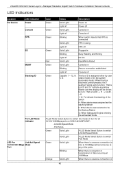
... entering the exhausted mode. xStack® DGS-3420 Series Layer 2+ Managed Stackable Gigabit Switch Hardware Installation Reference Guide LED Indicators Location Per Device LED Indicative Power Console RPS SD MGMT Stacking ID Port LED Mode Indicator LED Per Link/Act/Speed 10/100/1000 Mbps Mode Port Color Status Description Green Solid Light Power on Light off Power off Green Solid Light Console on Light off Console off Green Blinking When switch detects that RPS is connected Solid Light RPS in using Light off RPS off Green Solid Light Plugged in turn .
... entering the exhausted mode. xStack® DGS-3420 Series Layer 2+ Managed Stackable Gigabit Switch Hardware Installation Reference Guide LED Indicators Location Per Device LED Indicative Power Console RPS SD MGMT Stacking ID Port LED Mode Indicator LED Per Link/Act/Speed 10/100/1000 Mbps Mode Port Color Status Description Green Solid Light Power on Light off Power off Green Solid Light Console on Light off Console off Green Blinking When switch detects that RPS is connected Solid Light RPS in using Light off RPS off Green Solid Light Plugged in turn .

Hardware Installation Guide
Page 44
... out-of the ports. xStack® DGS-3420 Series Layer 2+ Managed Stackable Gigabit Switch Hardware Installation Reference Guide PoE Mode LED per SFP Port Link/Act LED per SFP+ Port Link/Act Off Green Orange Off Green Orange Off Green Orange Off Blinking Light off Solid Light Solid Light Light Off Solid Light Blinking Solid Light Blinking Light off Solid Light Blinking Solid Light Blinking Light off link) to 10/100Mbps Ethernet device at 1000Mbps. Error Condition. When there is a secure connection (or link) to 1000Mbps Ethernet device at any of -band CLI configuration 10/100...
... out-of the ports. xStack® DGS-3420 Series Layer 2+ Managed Stackable Gigabit Switch Hardware Installation Reference Guide PoE Mode LED per SFP Port Link/Act LED per SFP+ Port Link/Act Off Green Orange Off Green Orange Off Green Orange Off Blinking Light off Solid Light Solid Light Light Off Solid Light Blinking Solid Light Blinking Light off Solid Light Blinking Solid Light Blinking Light off link) to 10/100Mbps Ethernet device at 1000Mbps. Error Condition. When there is a secure connection (or link) to 1000Mbps Ethernet device at any of -band CLI configuration 10/100...


