Product Manual
Page 2
... Cord...3 Power Failure ...3 Getting Started...4 Management Options...4 Using Web-based Management Utility...4 Supported Web Browsers ...4 Connecting to the Switch...4 Login Web-based Management Utility ...5 Smart Wizard ...5 Web-based Management Utility...5 SmartConsole Utility...5 Product Introduction ...7 DGS-1216T ...7 Front Panel ...7 Rear Panel...8 DGS-1224T ...8 Front Panel ...8 Rear Panel...9 DGS-1224TP...9 Front Panel ...9 Rear Panel...10 DGS-1248T ...10 Front Panel ...10 Rear Panel...11...
... Cord...3 Power Failure ...3 Getting Started...4 Management Options...4 Using Web-based Management Utility...4 Supported Web Browsers ...4 Connecting to the Switch...4 Login Web-based Management Utility ...5 Smart Wizard ...5 Web-based Management Utility...5 SmartConsole Utility...5 Product Introduction ...7 DGS-1216T ...7 Front Panel ...7 Rear Panel...8 DGS-1224T ...8 Front Panel ...8 Rear Panel...9 DGS-1224TP...9 Front Panel ...9 Rear Panel...10 DGS-1248T ...10 Front Panel ...10 Rear Panel...11...
Product Manual
Page 3
... ...3 L2 Features ...3 VLAN ...3 ii Ethernet Technology...1 Gigabit Ethernet Technology ...1 Fast Ethernet Technology...1 Switching Technology ...1 Power over Ethernet (PoE) > PoE System Settings (Only for DGS-1224TP 36 QoS > 802.1p/DSCP Priority Settings...37 Security > Trusted Host...38 Security > Safeguard Engine...> Statistics ...42 Monitoring > Cable Diagnostics ...42 Appendix A - Table of Contents D-Link Web Smart Switch User Manual SNMP Settings ...20 System Settings...21 Identifying the Web-based Management Utility 22 Tool Menu ...22 Reset ...22 Configure Backup & Restore...23 ...
... ...3 L2 Features ...3 VLAN ...3 ii Ethernet Technology...1 Gigabit Ethernet Technology ...1 Fast Ethernet Technology...1 Switching Technology ...1 Power over Ethernet (PoE) > PoE System Settings (Only for DGS-1224TP 36 QoS > 802.1p/DSCP Priority Settings...37 Security > Trusted Host...38 Security > Safeguard Engine...> Statistics ...42 Monitoring > Cable Diagnostics ...42 Appendix A - Table of Contents D-Link Web Smart Switch User Manual SNMP Settings ...20 System Settings...21 Identifying the Web-based Management Utility 22 Tool Menu ...22 Reset ...22 Configure Backup & Restore...23 ...
Product Manual
Page 13
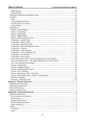
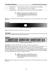
...is connected to connect the AC power cord. 3 Product Introduction Rear Panel D-Link Web Smart Switch User Manual Figure 11 - DGS-1224TP Front Panel Power LED: The Power LED flashes when the Switch is sending or receiving on corresponding port at 1000Mbps 9 CPU LED: When the...Link/Act Off The corresponding port is link down Solid Green The corresponding port is link up at 1000Mbps Blinking Green Data is sending or receiving on corresponding port at 1000Mbps Solid Orange The corresponding port is selected. DGS-1224T Rear Panel Reset: By pressing the Reset button the Switch...
...is connected to connect the AC power cord. 3 Product Introduction Rear Panel D-Link Web Smart Switch User Manual Figure 11 - DGS-1224TP Front Panel Power LED: The Power LED flashes when the Switch is sending or receiving on corresponding port at 1000Mbps 9 CPU LED: When the...Link/Act Off The corresponding port is link down Solid Green The corresponding port is link up at 1000Mbps Blinking Green Data is sending or receiving on corresponding port at 1000Mbps Solid Orange The corresponding port is selected. DGS-1224T Rear Panel Reset: By pressing the Reset button the Switch...
Product Manual
Page 14
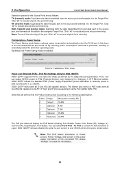
...up at 100Mbps Data is sending or receiving on corresponding port at 100Mbps NOTE: On DGS-1224TP, the MiniGBIC ports 21F to 24F are shared with 4 Combo SFP Smart Switch Front Panel Figure 14 - DGS-1248T 48 Port 10/100/1000BaseT with normal RJ-45 ports 45T to 48F are ...AC power cord. When MiniGBIC port is used, the RJ-45 port cannot be used . NOTE: On DGS-1248T, the MiniGBIC ports 45F to 48T. 3 Product Introduction D-Link Web Smart Switch User Manual Blinking Green Solid Orange Blinking Orange Data is sending or receiving on corresponding port at 1000Mbps The ...
...up at 100Mbps Data is sending or receiving on corresponding port at 100Mbps NOTE: On DGS-1224TP, the MiniGBIC ports 21F to 24F are shared with 4 Combo SFP Smart Switch Front Panel Figure 14 - DGS-1248T 48 Port 10/100/1000BaseT with normal RJ-45 ports 45T to 48F are ...AC power cord. When MiniGBIC port is used, the RJ-45 port cannot be used . NOTE: On DGS-1248T, the MiniGBIC ports 45F to 48T. 3 Product Introduction D-Link Web Smart Switch User Manual Blinking Green Solid Orange Blinking Orange Data is sending or receiving on corresponding port at 1000Mbps The ...
Product Manual
Page 39
...Click "all" to remove all the data to the Target Port. DGS-1224TP follows the standard PSE (Power Supply Equipment) pinout Alternative A, whereby power is produced, resulting in PoE mode with all D-Link 802.3af capable devices. please "Refresh" to the Target Port. Figure...sent to the source and forwards it to renew the information. 35 The Switch also works in extended product life and lower operating costs. 5 Configuration D-Link Web Smart Switch User Manual Selection options for DGS-1224TP) DGS-1224TP supports Power over Ethernet (PoE) as follows: TX (transmit) mode: ...
...Click "all" to remove all the data to the Target Port. DGS-1224TP follows the standard PSE (Power Supply Equipment) pinout Alternative A, whereby power is produced, resulting in PoE mode with all D-Link 802.3af capable devices. please "Refresh" to the Target Port. Figure...sent to the source and forwards it to renew the information. 35 The Switch also works in extended product life and lower operating costs. 5 Configuration D-Link Web Smart Switch User Manual Selection options for DGS-1224TP) DGS-1224TP supports Power over Ethernet (PoE) as follows: TX (transmit) mode: ...
Product Manual
Page 40
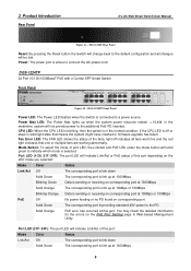
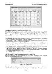
5 Configuration D-Link Web Smart Switch User Manual Figure 62 - PoE > PoE System Setting System Power Threshold: When the ratio of diagnostic messages Normal: There is no PD is larger ... - PoE > PoE Port Setting PoE Enable: Select to check the status of the cable and define the distance of corresponding PoE port; To protect the DGS-1224TP and the connected devices, the power limit function will display the PoE status including System Budget Power, Support Total Power, Remainder Power, and The ratio...
5 Configuration D-Link Web Smart Switch User Manual Figure 62 - PoE > PoE System Setting System Power Threshold: When the ratio of diagnostic messages Normal: There is no PD is larger ... - PoE > PoE Port Setting PoE Enable: Select to check the status of the cable and define the distance of corresponding PoE port; To protect the DGS-1224TP and the connected devices, the power limit function will display the PoE status including System Budget Power, Support Total Power, Remainder Power, and The ratio...
Product Manual
Page 50
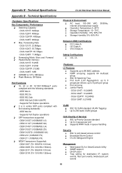
Technical Specifications D-Link Web Smart Switch User Manual Appendix B - DGS-1224TP: 48Gbps - IEEE 802.3 - IEEE 802.3af (DGS-1224TP) - IEEE 802.3z - DEM-312GT2 (1000BASE-SX) - DEM-330T (TX-1550/RX-1310nm) - DEM-331T (TX-1550/RX-1310nm) - DGS-1224T: 10,240KB - DGS-1224TP: 35.7Mpps - DGS-1216T: 512KB - DGS-1224TP: 512KB - IEEE 802.3u - IEEE 802.3ab - DEM-310GT (1000BASE-LX) - DEM-311GT (1000BASE-SX...
Technical Specifications D-Link Web Smart Switch User Manual Appendix B - DGS-1224TP: 48Gbps - IEEE 802.3 - IEEE 802.3af (DGS-1224TP) - IEEE 802.3z - DEM-312GT2 (1000BASE-SX) - DEM-330T (TX-1550/RX-1310nm) - DEM-331T (TX-1550/RX-1310nm) - DGS-1224T: 10,240KB - DGS-1224TP: 35.7Mpps - DGS-1216T: 512KB - DGS-1224TP: 512KB - IEEE 802.3u - IEEE 802.3ab - DEM-310GT (1000BASE-LX) - DEM-311GT (1000BASE-SX...


