
Hardware Installation Guide
Page 6
... PC 2-17 Connecting the Power Supply 2-18 Mounting Your Router 2-18 Mounting on a Table 2-18 Mounting on a Wall 2-19 Verifying Installation 2-20 Where to Go from Here 2-22 Troubleshooting 3-1 Problems During First Startup 3-2 Problems After First Startup 3-3 Problems After Router Is Running 3-5 When Contacting Your Cisco Reseller 3-7 ISDN and IDSL Concepts A-1 Specifications and Cables B-1 System Specifications B-1 Port Connector Pinouts B-2 Cabling Specifications B-6 Ethernet Cable Specifications B-7 Maximum Cable Distances B-7 Cisco 800 Series Routers Hardware Installation Guide vi 78-5373...
... PC 2-17 Connecting the Power Supply 2-18 Mounting Your Router 2-18 Mounting on a Table 2-18 Mounting on a Wall 2-19 Verifying Installation 2-20 Where to Go from Here 2-22 Troubleshooting 3-1 Problems During First Startup 3-2 Problems After First Startup 3-3 Problems After Router Is Running 3-5 When Contacting Your Cisco Reseller 3-7 ISDN and IDSL Concepts A-1 Specifications and Cables B-1 System Specifications B-1 Port Connector Pinouts B-2 Cabling Specifications B-6 Ethernet Cable Specifications B-7 Maximum Cable Distances B-7 Cisco 800 Series Routers Hardware Installation Guide vi 78-5373...
Hardware Installation Guide
Page 7
... or references to the network as quickly as installing, mounting, and verifying the connections to your router. • Troubleshooting-Describes how to identify and solve problems with your router. • ISDN and IDSL Concepts-Describes how ISDN is to connect the router to additional information and material. 78-5373-04 Cisco 800 Series Routers Hardware Installation Guide vii Where relevant, this guide explains how the router is intended for service technicians...
... or references to the network as quickly as installing, mounting, and verifying the connections to your router. • Troubleshooting-Describes how to identify and solve problems with your router. • ISDN and IDSL Concepts-Describes how ISDN is to connect the router to additional information and material. 78-5373-04 Cisco 800 Series Routers Hardware Installation Guide vii Where relevant, this guide explains how the router is intended for service technicians...
Hardware Installation Guide
Page 10
... bug-doc@cisco.com. We test our products internally before we release them, and we strive to the following address: Cisco Systems Attn: Customer Document Ordering 170 West Tasman Drive San Jose, CA 95134-9883 We appreciate your comments. psirt@cisco.com Cisco 800 Series Routers Hardware Installation Guide x 78-5373-04 security-alert@cisco.com • Nonemergencies - Cisco Product Security Overview Cisco provides a free online Security Vulnerability Policy...
... bug-doc@cisco.com. We test our products internally before we release them, and we strive to the following address: Cisco Systems Attn: Customer Document Ordering 170 West Tasman Drive San Jose, CA 95134-9883 We appreciate your comments. psirt@cisco.com Cisco 800 Series Routers Hardware Installation Guide x 78-5373-04 security-alert@cisco.com • Nonemergencies - Cisco Product Security Overview Cisco provides a free online Security Vulnerability Policy...
Hardware Installation Guide
Page 11
... at this URL: http://tools.cisco.com/RPF/register/register.do not have a user ID or password, you have a valid service contract but do Note Use the Cisco Product Identification (CPI) tool to use a revoked or an expired encryption key. by copying and pasting show an illustration of your product serial number before placing a service call. 78-5373-04 Cisco 800 Series Routers Hardware Installation Guide xi
... at this URL: http://tools.cisco.com/RPF/register/register.do not have a user ID or password, you have a valid service contract but do Note Use the Cisco Product Identification (CPI) tool to use a revoked or an expired encryption key. by copying and pasting show an illustration of your product serial number before placing a service call. 78-5373-04 Cisco 800 Series Routers Hardware Installation Guide xi
Hardware Installation Guide
Page 16
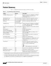
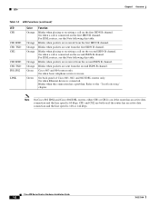
.... The Cisco product number for basic configurations. Supports Cisco IOS software. Cisco 800 Series Routers Hardware Installation Guide 1-2 78-5373-04 Compatible with 10/100-Mbps devices. Cable lock All Provides a way to IDSL network. Provides connection to physically secure the router. Table 1-1 Cisco 800 Series Feature Summary Feature 10BASE-T Ethernet port(s) ISDN BRI S/T port ISDN BRI U port IDSL port Telephone ports Internal Network Termination 1 (NT1) Flash memory Dynamic RAM (DRAM) Easily distinguishable ISDN B-channel LEDs Ease of DRAM can order upgrade kits and...
.... The Cisco product number for basic configurations. Supports Cisco IOS software. Cisco 800 Series Routers Hardware Installation Guide 1-2 78-5373-04 Compatible with 10/100-Mbps devices. Cable lock All Provides a way to IDSL network. Provides connection to physically secure the router. Table 1-1 Cisco 800 Series Feature Summary Feature 10BASE-T Ethernet port(s) ISDN BRI S/T port ISDN BRI U port IDSL port Telephone ports Internal Network Termination 1 (NT1) Flash memory Dynamic RAM (DRAM) Easily distinguishable ISDN B-channel LEDs Ease of DRAM can order upgrade kits and...

Hardware Installation Guide
Page 18
... port directly to a public network that follows the European Union standards. device connection. Connecting the port to a public network that follows the European Union standards. Locking power connector Connect power supply. Power switch l = On. = Standby or no power output. 11666 LINK HUB NO HUB ETHERNET 10 BASE T Cisco 801 CONSOLE ISDN S/T Cable lock Use cable lock to external NT1 or ISDN wall jack. Cisco 800 Series Routers Hardware Installation Guide 1-4 78-5373-04 Ethernet port Connect Ethernet network device. Figure 1-4 Cisco 801 Router Back Panel Link LED...
... port directly to a public network that follows the European Union standards. device connection. Connecting the port to a public network that follows the European Union standards. Locking power connector Connect power supply. Power switch l = On. = Standby or no power output. 11666 LINK HUB NO HUB ETHERNET 10 BASE T Cisco 801 CONSOLE ISDN S/T Cable lock Use cable lock to external NT1 or ISDN wall jack. Cisco 800 Series Routers Hardware Installation Guide 1-4 78-5373-04 Ethernet port Connect Ethernet network device. Figure 1-4 Cisco 801 Router Back Panel Link LED...

Hardware Installation Guide
Page 19
... Installation Guide 1-5 Locking power connector Connect power supply. 11667 Figure 1-6 Cisco 803 Router Back Panel Ethernet ports Connect Ethernet network devices. HUB NO HUB ETHERNET 10 BASE T 0 1 2 3 Cisco 803 CONSOLE ISDN S/T HUB/NO HUB button (for Ethernet port 0) Determines cable type for Ethernet device connection. ISDN BRI S/T port Connect to physically secure router. Telephone ports Connect to physically secure router. Power switch l = On. = Standby or no power output. Chapter 1 Overview Back Panels Figure 1-5 Cisco 802 Router Back Panel Link LED...
... Installation Guide 1-5 Locking power connector Connect power supply. 11667 Figure 1-6 Cisco 803 Router Back Panel Ethernet ports Connect Ethernet network devices. HUB NO HUB ETHERNET 10 BASE T 0 1 2 3 Cisco 803 CONSOLE ISDN S/T HUB/NO HUB button (for Ethernet port 0) Determines cable type for Ethernet device connection. ISDN BRI S/T port Connect to physically secure router. Telephone ports Connect to physically secure router. Power switch l = On. = Standby or no power output. Chapter 1 Overview Back Panels Figure 1-5 Cisco 802 Router Back Panel Link LED...

Hardware Installation Guide
Page 20
... Ethernet port) Determines cable type for Ethernet device connection. Locking power connector Connect power supply. 30771 Cisco 800 Series Routers Hardware Installation Guide 1-6 78-5373-04 HUB NO HUB ETHERNET 10 BASE T 0 1 2 3 HUB/NO HUB button (for Ethernet port 0) Determines cable type for Ethernet device connection. LINK TO TO HUB PC ETHERNET 10 BASE T CONSOLE Cisco 802 IDSL IDSL Cable lock Use cable lock to ISDN wall jack. Console port Connect PC or terminal. Figure 1-8 Cisco 802 IDSL Router Back Panel Link LED Indicates state of Ethernet port. Cisco 804 CONSOLE...
... Ethernet port) Determines cable type for Ethernet device connection. Locking power connector Connect power supply. 30771 Cisco 800 Series Routers Hardware Installation Guide 1-6 78-5373-04 HUB NO HUB ETHERNET 10 BASE T 0 1 2 3 HUB/NO HUB button (for Ethernet port 0) Determines cable type for Ethernet device connection. LINK TO TO HUB PC ETHERNET 10 BASE T CONSOLE Cisco 802 IDSL IDSL Cable lock Use cable lock to ISDN wall jack. Console port Connect PC or terminal. Figure 1-8 Cisco 802 IDSL Router Back Panel Link LED Indicates state of Ethernet port. Cisco 804 CONSOLE...

Hardware Installation Guide
Page 21
... device are synchronized. See the "Troubleshooting" chapter. 78-5373-04 Cisco 800 Series Routers Hardware Installation Guide 1-7 Locking power connector Connect power supply. LEDs Table 1-3 summarizes the function of each LED. On when packets are attempting to the router and when the router completes the self-test procedure and begins operating. Blinks when an Ethernet port sends a packet. TO TO HUB PC ETHERNET 10 BASE T 1 2 3 4 TO HUB/TO PC (for Ethernet port 1) Determines cable type for Cisco...
... device are synchronized. See the "Troubleshooting" chapter. 78-5373-04 Cisco 800 Series Routers Hardware Installation Guide 1-7 Locking power connector Connect power supply. LEDs Table 1-3 summarizes the function of each LED. On when packets are attempting to the router and when the router completes the self-test procedure and begins operating. Blinks when an Ethernet port sends a packet. TO TO HUB PC ETHERNET 10 BASE T 1 2 3 4 TO HUB/TO PC (for Ethernet port 1) Determines cable type for Cisco...
Hardware Installation Guide
Page 22
... ISDN B channel. On when a call on if the router has an active data connection and the line speed is 64 kbps. On when basic telephone service is connected. Note On Cisco 802 IDSL and Cisco 804 IDSL routers, either CH1 or CH2 is on the first ISDN B channel. Blinks when packets are received from the second ISDN B channel. Blinks when the connection has a problem. Cisco 800 Series Routers Hardware Installation Guide 1-8 78...
... ISDN B channel. On when a call on if the router has an active data connection and the line speed is 64 kbps. On when basic telephone service is connected. Note On Cisco 802 IDSL and Cisco 804 IDSL routers, either CH1 or CH2 is on the first ISDN B channel. Blinks when packets are received from the second ISDN B channel. Blinks when the connection has a problem. Cisco 800 Series Routers Hardware Installation Guide 1-8 78...

Hardware Installation Guide
Page 23
Installation CH A P T E R 2 This chapter provides information on the following topics: • Safety • European Union Statements • Preventing Electrostatic Discharge Damage • Preventing Router Damage • Unpacking Your Router • Preinstallation Activities • Installing Your Router • Mounting Your Router • Verifying Installation • Where to Go from Here 78-5373-04 Cisco 800 Series Routers Hardware Installation Guide 2-1
Installation CH A P T E R 2 This chapter provides information on the following topics: • Safety • European Union Statements • Preventing Electrostatic Discharge Damage • Preventing Router Damage • Unpacking Your Router • Preinstallation Activities • Installing Your Router • Mounting Your Router • Verifying Installation • Where to Go from Here 78-5373-04 Cisco 800 Series Routers Hardware Installation Guide 2-1
Hardware Installation Guide
Page 24
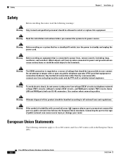
... equipment. Use caution when connecting cables. Cisco 800 Series Routers Hardware Installation Guide 2-2 78-5373-04 Warning Before working on a system that is regarded as a source of this product should be inaccessible to install or replace this type of suitability with or open any public telephone operator (PTO)-provided equipment or connection hardware. Any hardwired connection (other than by PTO staff or suitably trained engineers. LAN ports contain SELV...
... equipment. Use caution when connecting cables. Cisco 800 Series Routers Hardware Installation Guide 2-2 78-5373-04 Warning Before working on a system that is regarded as a source of this product should be inaccessible to install or replace this type of suitability with or open any public telephone operator (PTO)-provided equipment or connection hardware. Any hardwired connection (other than by PTO staff or suitably trained engineers. LAN ports contain SELV...

Hardware Installation Guide
Page 26
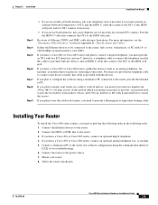
... a Cisco 801 or Cisco 803 router, do the following: Cisco 800 Series Routers Hardware Installation Guide 2-4 78-5373-04 Connecting the port to this appendix does not provide specifications for use with your customer service representative. If any of public network can connect the port directly to the Cisco 800 Series Routers Software Configuration Guide. For more information, refer to a public network that come with light blue console cable • ISDN ST cable (orange) (Cisco 801 and 803 routers) • Ethernet cable (yellow...
... a Cisco 801 or Cisco 803 router, do the following: Cisco 800 Series Routers Hardware Installation Guide 2-4 78-5373-04 Connecting the port to this appendix does not provide specifications for use with your customer service representative. If any of public network can connect the port directly to the Cisco 800 Series Routers Software Configuration Guide. For more information, refer to a public network that come with light blue console cable • ISDN ST cable (orange) (Cisco 801 and 803 routers) • Ethernet cable (yellow...
Hardware Installation Guide
Page 27
... cable. Verify the router installation. 78-5373-04 Cisco 800 Series Routers Hardware Installation Guide 2-5 Connect a terminal or PC to the router, provide the terminal or PC. Connect the ISDN or IDSL line to the router. Mount your telephone service provider for troubleshooting). 6. For more information, see the "Maximum Cable Distances" section in . (M3.5 x 20 mm) screws. or 10/100-Mbps network interface card (NIC). If you have a Cisco 801 or Cisco 803 router...
... cable. Verify the router installation. 78-5373-04 Cisco 800 Series Routers Hardware Installation Guide 2-5 Connect a terminal or PC to the router, provide the terminal or PC. Connect the ISDN or IDSL line to the router. Mount your telephone service provider for troubleshooting). 6. For more information, see the "Maximum Cable Distances" section in . (M3.5 x 20 mm) screws. or 10/100-Mbps network interface card (NIC). If you have a Cisco 801 or Cisco 803 router...
Hardware Installation Guide
Page 28
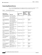
.../TO Ethernet port PC button Cisco 804 IDSL router: Ethernet port 1 Hub without equivalent Cisco 803 and 804 to router HUB/NO routers: HUB button Ethernet ports 1, 2, 3 Hub without equivalent Cisco 804 IDSL router: to the router, connections for each device, and the settings of the router HUB/NO HUB or TO HUB/TO PC button (the default setting is IN). Installing Your Router Chapter 2 Installation Connecting Ethernet Devices Table 2-2 lists the Ethernet devices you can connect to router TO HUB/TO Ethernet ports 2, 3, 4 PC button Ethernet Cable Type1 Router HUB...
.../TO Ethernet port PC button Cisco 804 IDSL router: Ethernet port 1 Hub without equivalent Cisco 803 and 804 to router HUB/NO routers: HUB button Ethernet ports 1, 2, 3 Hub without equivalent Cisco 804 IDSL router: to the router, connections for each device, and the settings of the router HUB/NO HUB or TO HUB/TO PC button (the default setting is IN). Installing Your Router Chapter 2 Installation Connecting Ethernet Devices Table 2-2 lists the Ethernet devices you can connect to router TO HUB/TO Ethernet ports 2, 3, 4 PC button Ethernet Cable Type1 Router HUB...
Hardware Installation Guide
Page 30
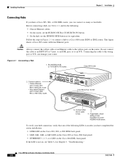
... 101S00PBBEaasEseeDTTX LED SOLID BLINK 1 5 2 6 3 7 4 8 2X ETHERNET 3X 4X 6X 7X 8X MDI MDI-X 3. Connect other end of router HUB/NO HUB button. Follow the steps in Chapter 3, "Troubleshooting." Connecting the cable to : • Yellow Ethernet port on Cisco 801, 802 or 802 IDSL router. • Any yellow Ethernet port on the router. Figure 2-1 Connecting a Hub 1. Connect cable to the wrong port or NT1 can connect as many as four hubs. Cisco 800 Series Routers Hardware Installation Guide...
... 101S00PBBEaasEseeDTTX LED SOLID BLINK 1 5 2 6 3 7 4 8 2X ETHERNET 3X 4X 6X 7X 8X MDI MDI-X 3. Connect other end of router HUB/NO HUB button. Follow the steps in Chapter 3, "Troubleshooting." Connecting the cable to : • Yellow Ethernet port on Cisco 801, 802 or 802 IDSL router. • Any yellow Ethernet port on the router. Figure 2-1 Connecting a Hub 1. Connect cable to the wrong port or NT1 can connect as many as four hubs. Cisco 800 Series Routers Hardware Installation Guide...
Hardware Installation Guide
Page 31
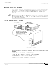
... HUB ETHERNET 10 BASE T 0 1 2 3 Cisco 803 CONSOLE ISDN S/T PHONE 1 2 2. Chapter 2 Installation Installing Your Router Connecting a Server, PC, or Workstation Before connecting the server, PC, or workstation, refer to Table 2-2 to determine how to an NT1. To connect one of cable to the wrong port or NT1 can damage your device has a 10- or 10/100-Mbps NIC. Connecting the cable to server, PC, or workstation. PC ETH SER 0 OK LAN 11675...
... HUB ETHERNET 10 BASE T 0 1 2 3 Cisco 803 CONSOLE ISDN S/T PHONE 1 2 2. Chapter 2 Installation Installing Your Router Connecting a Server, PC, or Workstation Before connecting the server, PC, or workstation, refer to Table 2-2 to determine how to an NT1. To connect one of cable to the wrong port or NT1 can damage your device has a 10- or 10/100-Mbps NIC. Connecting the cable to server, PC, or workstation. PC ETH SER 0 OK LAN 11675...
Hardware Installation Guide
Page 42
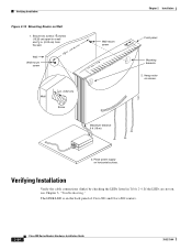
... horizontal surface. Place power supply on screws. 3. Verifying Installation Verify the cable connections (links) by checking the LEDs listed in . (0.32 cm) Screw Maximum distance 6 ft (18 m) 11672 Chapter 2 Installation Front panel Mounting brackets 2. The LINK LED is on , see Chapter 3, "Troubleshooting." If the LEDs are not on the back panel of Cisco 801 and Cisco 802 routers. 2-20 Cisco 800 Series Routers Hardware Installation Guide 78-5373-04 Secure two screws 7 5 8 inches (19.35 cm) apart...
... horizontal surface. Place power supply on screws. 3. Verifying Installation Verify the cable connections (links) by checking the LEDs listed in . (0.32 cm) Screw Maximum distance 6 ft (18 m) 11672 Chapter 2 Installation Front panel Mounting brackets 2. The LINK LED is on , see Chapter 3, "Troubleshooting." If the LEDs are not on the back panel of Cisco 801 and Cisco 802 routers. 2-20 Cisco 800 Series Routers Hardware Installation Guide 78-5373-04 Secure two screws 7 5 8 inches (19.35 cm) apart...

Hardware Installation Guide
Page 47
... in parts of Europe, you are using the right type of North America, contact your own cable, make sure it . • Improperly set buttons correctly, see Table 2-2 in Appendix B, "Specifications and Cables," to an Ethernet device. (On Cisco 801, Cisco 802, and 802 IDSL routers, the LINK LED on server, PC, or workstation. • Run the NIC diagnostic supplied by the vendor to ISDN or IDSL network. (NT1, LINE, CH1...
... in parts of Europe, you are using the right type of North America, contact your own cable, make sure it . • Improperly set buttons correctly, see Table 2-2 in Appendix B, "Specifications and Cables," to an Ethernet device. (On Cisco 801, Cisco 802, and 802 IDSL routers, the LINK LED on server, PC, or workstation. • Run the NIC diagnostic supplied by the vendor to ISDN or IDSL network. (NT1, LINE, CH1...

Hardware Installation Guide
Page 69
... router 2-4, ?? Index S S/T interface A-1 safety warnings 2-2 server, connecting 2-9 settings, network devices 2-6 to 2-7 specifications cabling B-6 system B-1 startup problems 3-2 T table mounting 2-18 telephone connecting 2-14, 2-15 ports described 1-2 illustrated 1-5, 1-6 temperature specifications B-1 terminal, connecting 2-17 TO HUB/TO PC button illustrated 1-6 to 1-7 settings 2-6 to 2-20 warnings, installation 2-2 weight specifications B-1 workstation, connecting 2-9 U U interface A-1 United Kingdom master sockets 2-16 78-5373-04 Cisco 800 Series Routers Hardware Installation Guide...
... router 2-4, ?? Index S S/T interface A-1 safety warnings 2-2 server, connecting 2-9 settings, network devices 2-6 to 2-7 specifications cabling B-6 system B-1 startup problems 3-2 T table mounting 2-18 telephone connecting 2-14, 2-15 ports described 1-2 illustrated 1-5, 1-6 temperature specifications B-1 terminal, connecting 2-17 TO HUB/TO PC button illustrated 1-6 to 1-7 settings 2-6 to 2-20 warnings, installation 2-2 weight specifications B-1 workstation, connecting 2-9 U U interface A-1 United Kingdom master sockets 2-16 78-5373-04 Cisco 800 Series Routers Hardware Installation Guide...


