Hardware Installation Guide
Page 6
... PC 2-17 Connecting the Power Supply 2-18 Mounting Your Router 2-18 Mounting on a Table 2-18 Mounting on a Wall 2-19 Verifying Installation 2-20 Where to Go from Here 2-22 Troubleshooting 3-1 Problems During First Startup 3-2 Problems After First Startup 3-3 Problems After Router Is Running 3-5 When Contacting Your Cisco Reseller 3-7 ISDN and IDSL Concepts A-1 Specifications and Cables B-1 System Specifications B-1 Port Connector Pinouts B-2 Cabling Specifications B-6 Ethernet Cable Specifications B-7 Maximum Cable Distances B-7 Cisco 800 Series Routers Hardware Installation Guide vi 78-5373...
... PC 2-17 Connecting the Power Supply 2-18 Mounting Your Router 2-18 Mounting on a Table 2-18 Mounting on a Wall 2-19 Verifying Installation 2-20 Where to Go from Here 2-22 Troubleshooting 3-1 Problems During First Startup 3-2 Problems After First Startup 3-3 Problems After Router Is Running 3-5 When Contacting Your Cisco Reseller 3-7 ISDN and IDSL Concepts A-1 Specifications and Cables B-1 System Specifications B-1 Port Connector Pinouts B-2 Cabling Specifications B-6 Ethernet Cable Specifications B-7 Maximum Cable Distances B-7 Cisco 800 Series Routers Hardware Installation Guide vi 78-5373...
Hardware Installation Guide
Page 7
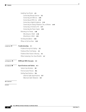
.... 78-5373-04 Cisco 800 Series Routers Hardware Installation Guide vii Conventions This section describes the conventions used in this guide. Where relevant, this guide explains how the router is usually in a separate section or appendix so that technicians who are not interested can skip this guide, and how to access related documentation. • Overview-Contains router features and a description of router LEDs, ports, and other components...
.... 78-5373-04 Cisco 800 Series Routers Hardware Installation Guide vii Conventions This section describes the conventions used in this guide. Where relevant, this guide explains how the router is usually in a separate section or appendix so that technicians who are not interested can skip this guide, and how to access related documentation. • Overview-Contains router features and a description of router LEDs, ports, and other components...
Hardware Installation Guide
Page 10
... order Cisco documentation in these tasks: • Report security vulnerabilities in Cisco products. • Obtain assistance with security incidents that you think that involve Cisco products. • Register to receive security information from Cisco. psirt@cisco.com Cisco 800 Series Routers Hardware Installation Guide x 78-5373-04 A current list of your comments. Cisco Product Security Overview Cisco provides a free online Security Vulnerability Policy portal at this URL: http://www.cisco.com/en/US...
... order Cisco documentation in these tasks: • Report security vulnerabilities in Cisco products. • Obtain assistance with security incidents that you think that involve Cisco products. • Register to receive security information from Cisco. psirt@cisco.com Cisco 800 Series Routers Hardware Installation Guide x 78-5373-04 A current list of your comments. Cisco Product Security Overview Cisco provides a free online Security Vulnerability Policy portal at this URL: http://www.cisco.com/en/US...
Hardware Installation Guide
Page 11
... send to locate your product serial number before placing a service call. 78-5373-04 Cisco 800 Series Routers Hardware Installation Guide xi Never use in this URL: http://tools.cisco.com/RPF/register/register.do not have a valid service contract but do Note Use the Cisco Product Identification (CPI) tool to Cisco. Locate the serial number label on Cisco.com features extensive online support resources. PSIRT can also reach...
... send to locate your product serial number before placing a service call. 78-5373-04 Cisco 800 Series Routers Hardware Installation Guide xi Never use in this URL: http://tools.cisco.com/RPF/register/register.do not have a valid service contract but do Note Use the Cisco Product Identification (CPI) tool to Cisco. Locate the serial number label on Cisco.com features extensive online support resources. PSIRT can also reach...
Hardware Installation Guide
Page 16
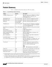
... factory or later. Cisco 800 Series Routers Hardware Installation Guide 1-2 78-5373-04 Cable lock All Provides a way to Cisco 802 and Cisco 804 routers. 2. Locking power connector All Locks power connector in a different color from other LEDs. An additional 8 MB of Flash memory and 4 or 8 MB of DRAM.2 ISDN B-channel LEDs in place. The Cisco product number for the 8-MB Flash memory upgrade kit is a service port. Supports Cisco IOS software. You cannot connect S/T devices to physically secure the router. Provide connection...
... factory or later. Cisco 800 Series Routers Hardware Installation Guide 1-2 78-5373-04 Cable lock All Provides a way to Cisco 802 and Cisco 804 routers. 2. Locking power connector All Locks power connector in a different color from other LEDs. An additional 8 MB of Flash memory and 4 or 8 MB of DRAM.2 ISDN B-channel LEDs in place. The Cisco product number for the 8-MB Flash memory upgrade kit is a service port. Supports Cisco IOS software. You cannot connect S/T devices to physically secure the router. Provide connection...

Hardware Installation Guide
Page 18
Ethernet port Connect Ethernet network device. Power switch l = On. = Standby or no power output. 11666 LINK HUB NO HUB ETHERNET 10 BASE T Cisco 801 CONSOLE ISDN S/T Cable lock Use cable lock to external NT1 or ISDN wall jack. device connection. Connecting the port to this section show the back panel of each of the Cisco 800 series routers. HUB/NO HUB button (for Ethernet port) Console port Determines cable Connect PC or type for Ethernet terminal. Locking power connector Connect power supply. Back Panels Figure 1-3 Cisco 804 IDSL Front Panel IDSL...
Ethernet port Connect Ethernet network device. Power switch l = On. = Standby or no power output. 11666 LINK HUB NO HUB ETHERNET 10 BASE T Cisco 801 CONSOLE ISDN S/T Cable lock Use cable lock to external NT1 or ISDN wall jack. device connection. Connecting the port to this section show the back panel of each of the Cisco 800 series routers. HUB/NO HUB button (for Ethernet port) Console port Determines cable Connect PC or type for Ethernet terminal. Locking power connector Connect power supply. Back Panels Figure 1-3 Cisco 804 IDSL Front Panel IDSL...

Hardware Installation Guide
Page 19
... power connector Connect power supply. 78-5373-04 Cisco 800 Series Routers Hardware Installation Guide 1-5 Ethernet port Connect Ethernet network device. Console port Connect PC or terminal. HUB NO HUB ETHERNET 10 BASE T 0 1 2 3 Cisco 803 CONSOLE ISDN S/T HUB/NO HUB button (for Ethernet port 0) Determines cable type for Ethernet device connection. Power switch l = On. = Standby or no power output. 11668 Cable lock Use cable lock to physically secure router. Chapter 1 Overview Back Panels Figure 1-5 Cisco 802 Router Back Panel Link LED Indicates state of Ethernet...
... power connector Connect power supply. 78-5373-04 Cisco 800 Series Routers Hardware Installation Guide 1-5 Ethernet port Connect Ethernet network device. Console port Connect PC or terminal. HUB NO HUB ETHERNET 10 BASE T 0 1 2 3 Cisco 803 CONSOLE ISDN S/T HUB/NO HUB button (for Ethernet port 0) Determines cable type for Ethernet device connection. Power switch l = On. = Standby or no power output. 11668 Cable lock Use cable lock to physically secure router. Chapter 1 Overview Back Panels Figure 1-5 Cisco 802 Router Back Panel Link LED Indicates state of Ethernet...

Hardware Installation Guide
Page 20
IDSL port Connect to physically secure router. Locking power connector Connect power supply. 30771 Cisco 800 Series Routers Hardware Installation Guide 1-6 78-5373-04 Cisco 804 CONSOLE ISDN U Console port Connect PC or terminal. PHONE 1 2 Locking power connector Connect power supply. LINK TO TO HUB PC ETHERNET 10 BASE T CONSOLE Cisco 802 IDSL IDSL Cable lock Use cable lock to IDSL wall jack. HUB NO HUB ETHERNET 10 BASE T 0 1 2 3 HUB/NO HUB button (for Ethernet port 0) Determines cable type for Ethernet device connection. Telephone ports Connect to ISDN wall ...
IDSL port Connect to physically secure router. Locking power connector Connect power supply. 30771 Cisco 800 Series Routers Hardware Installation Guide 1-6 78-5373-04 Cisco 804 CONSOLE ISDN U Console port Connect PC or terminal. PHONE 1 2 Locking power connector Connect power supply. LINK TO TO HUB PC ETHERNET 10 BASE T CONSOLE Cisco 802 IDSL IDSL Cable lock Use cable lock to IDSL wall jack. HUB NO HUB ETHERNET 10 BASE T 0 1 2 3 HUB/NO HUB button (for Ethernet port 0) Determines cable type for Ethernet device connection. Telephone ports Connect to ISDN wall ...

Hardware Installation Guide
Page 21
... ISDN switch are sent to physically secure router. See the "Troubleshooting" chapter. 78-5373-04 Cisco 800 Series Routers Hardware Installation Guide 1-7 Blinks when the connection has a problem. LEDs Table 1-3 summarizes the function of each LED. Off when the Ethernet device is not connected. Chapter 1 Overview LEDs Figure 1-9 Cisco 804 IDSL Router Back Panel Ethernet ports Connect Ethernet network devices. Off when the Ethernet device is not connected. TO TO HUB PC ETHERNET 10 BASE T 1 2 3 4 TO HUB/TO PC (for Ethernet port 1) Determines cable type for Cisco 801...
... ISDN switch are sent to physically secure router. See the "Troubleshooting" chapter. 78-5373-04 Cisco 800 Series Routers Hardware Installation Guide 1-7 Blinks when the connection has a problem. LEDs Table 1-3 summarizes the function of each LED. Off when the Ethernet device is not connected. Chapter 1 Overview LEDs Figure 1-9 Cisco 804 IDSL Router Back Panel Ethernet ports Connect Ethernet network devices. Off when the Ethernet device is not connected. TO TO HUB PC ETHERNET 10 BASE T 1 2 3 4 TO HUB/TO PC (for Ethernet port 1) Determines cable type for Cisco 801...
Hardware Installation Guide
Page 22
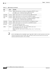
... this table. On back panel of Cisco 801, 802, and 802 IDSL routers only. Blinks when the connection has a problem. Refer to the "Troubleshooting" chapter. Cisco 800 Series Routers Hardware Installation Guide 1-8 78-5373-04 For IDSL routers, see the Note following this table. Blinks when packets are received from the first ISDN B channel. Blinks when packets are sent from the second ISDN B channel. Note On Cisco 802 IDSL and Cisco 804 IDSL routers...
... this table. On back panel of Cisco 801, 802, and 802 IDSL routers only. Blinks when the connection has a problem. Refer to the "Troubleshooting" chapter. Cisco 800 Series Routers Hardware Installation Guide 1-8 78-5373-04 For IDSL routers, see the Note following this table. Blinks when packets are received from the first ISDN B channel. Blinks when packets are sent from the second ISDN B channel. Note On Cisco 802 IDSL and Cisco 804 IDSL routers...

Hardware Installation Guide
Page 23
Installation CH A P T E R 2 This chapter provides information on the following topics: • Safety • European Union Statements • Preventing Electrostatic Discharge Damage • Preventing Router Damage • Unpacking Your Router • Preinstallation Activities • Installing Your Router • Mounting Your Router • Verifying Installation • Where to Go from Here 78-5373-04 Cisco 800 Series Routers Hardware Installation Guide 2-1
Installation CH A P T E R 2 This chapter provides information on the following topics: • Safety • European Union Statements • Preventing Electrostatic Discharge Damage • Preventing Router Damage • Unpacking Your Router • Preinstallation Activities • Installing Your Router • Mounting Your Router • Verifying Installation • Where to Go from Here 78-5373-04 Cisco 800 Series Routers Hardware Installation Guide 2-1
Hardware Installation Guide
Page 24
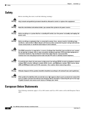
... installation instructions before you must be inaccessible to user contact. LAN ports contain SELV circuits, and WAN ports contain TNV circuits. Safety Chapter 2 Installation Safety Before installing the router, read the following statements apply to Cisco 801 routers and Cisco 803 routers sold in the European Union (EU). Warning Before working on equipment that has a standby/off switch, turn the power to telephone-network voltage (TNV) circuits. Use caution when connecting cables...
... installation instructions before you must be inaccessible to user contact. LAN ports contain SELV circuits, and WAN ports contain TNV circuits. Safety Chapter 2 Installation Safety Before installing the router, read the following statements apply to Cisco 801 routers and Cisco 803 routers sold in the European Union (EU). Warning Before working on equipment that has a standby/off switch, turn the power to telephone-network voltage (TNV) circuits. Use caution when connecting cables...

Hardware Installation Guide
Page 26
... this appendix does not provide specifications for use with your router came in Appendix B, "Specifications and Cables." If you must not connect the port to -RJ-11 adapter cable for a particular cable, we strongly recommend ordering the cable from your Cisco 800 series router, perform the following : Cisco 800 Series Routers Hardware Installation Guide 2-4 78-5373-04 If this type of suitability ( ) appears above a port, you must supply your router. Connecting the port to the Cisco 800 Series Routers Software Configuration Guide.
... this appendix does not provide specifications for use with your router came in Appendix B, "Specifications and Cables." If you must not connect the port to -RJ-11 adapter cable for a particular cable, we strongly recommend ordering the cable from your Cisco 800 series router, perform the following : Cisco 800 Series Routers Hardware Installation Guide 2-4 78-5373-04 If this type of suitability ( ) appears above a port, you must supply your router. Connecting the port to the Cisco 800 Series Routers Software Configuration Guide.
Hardware Installation Guide
Page 27
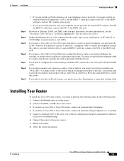
... router. 2. with the device), and an ISDN U cable that connects the NT1 to connect the telephone (usually this cable is provided with 5/16-in Appendix B, "Specifications and Cables." Mount your router. 8. Gather the Ethernet devices to be connected to the router: hub, server, workstation, or PC with 8-mm drill bit) to the router. 3. Connect the ISDN or IDSL line to secure the screws. Verify the router installation. 78-5373-04 Cisco 800 Series Routers Hardware Installation Guide...
... router. 2. with the device), and an ISDN U cable that connects the NT1 to connect the telephone (usually this cable is provided with 5/16-in Appendix B, "Specifications and Cables." Mount your router. 8. Gather the Ethernet devices to be connected to the router: hub, server, workstation, or PC with 8-mm drill bit) to the router. 3. Connect the ISDN or IDSL line to secure the screws. Verify the router installation. 78-5373-04 Cisco 800 Series Routers Hardware Installation Guide...
Hardware Installation Guide
Page 28
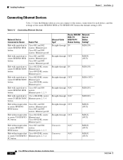
.../TO Ethernet port PC button Cisco 804 IDSL router: Ethernet port 1 Hub without equivalent Cisco 803 and 804 to router HUB/NO routers: HUB button Ethernet ports 1, 2, 3 Hub without equivalent Cisco 804 IDSL router: to the router, connections for each device, and the settings of the router HUB/NO HUB or TO HUB/TO PC button (the default setting is IN). Installing Your Router Chapter 2 Installation Connecting Ethernet Devices Table 2-2 lists the Ethernet devices you can connect to router TO HUB/TO Ethernet ports 2, 3, 4 PC button Ethernet Cable Type1 Router HUB...
.../TO Ethernet port PC button Cisco 804 IDSL router: Ethernet port 1 Hub without equivalent Cisco 803 and 804 to router HUB/NO routers: HUB button Ethernet ports 1, 2, 3 Hub without equivalent Cisco 804 IDSL router: to the router, connections for each device, and the settings of the router HUB/NO HUB or TO HUB/TO PC button (the default setting is IN). Installing Your Router Chapter 2 Installation Connecting Ethernet Devices Table 2-2 lists the Ethernet devices you can connect to router TO HUB/TO Ethernet ports 2, 3, 4 PC button Ethernet Cable Type1 Router HUB...
Hardware Installation Guide
Page 30
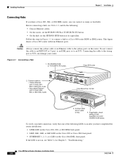
... LK3 LED on the Cisco 803 or Cisco 804 front panel. • ETHERNET 1, 2, 3, or 4 LED on the router. Cisco 800 Series Routers Hardware Installation Guide 2-8 78-5373-04 Set HUB/NO HUB or TO HUB/TO PC button. If applicable, check setting of hub equivalent of cable to the yellow ports on the Cisco 804 IDSL front panel. This figure shows a Cisco 803 router with four Ethernet ports. Caution Always connect the yellow cable or an Ethernet cable to...
... LK3 LED on the Cisco 803 or Cisco 804 front panel. • ETHERNET 1, 2, 3, or 4 LED on the router. Cisco 800 Series Routers Hardware Installation Guide 2-8 78-5373-04 Set HUB/NO HUB or TO HUB/TO PC button. If applicable, check setting of hub equivalent of cable to the yellow ports on the Cisco 804 IDSL front panel. This figure shows a Cisco 803 router with four Ethernet ports. Caution Always connect the yellow cable or an Ethernet cable to...
Hardware Installation Guide
Page 31
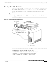
... the Cisco 803 or Cisco 804 front panel. • ETHERNET 1, 2, 3, or 4 LED on the router. To connect one of cable to a Cisco 800 series ISDN or IDSL router, follow the steps in Chapter 3, "Troubleshooting." 78-5373-04 Cisco 800 Series Routers Hardware Installation Guide 2-9 Chapter 2 Installation Installing Your Router Connecting a Server, PC, or Workstation Before connecting the server, PC, or workstation, refer to Table 2-2 to determine how to an NT1. Do not connect the cable to an ISDN S/T or U port...
... the Cisco 803 or Cisco 804 front panel. • ETHERNET 1, 2, 3, or 4 LED on the router. To connect one of cable to a Cisco 800 series ISDN or IDSL router, follow the steps in Chapter 3, "Troubleshooting." 78-5373-04 Cisco 800 Series Routers Hardware Installation Guide 2-9 Chapter 2 Installation Installing Your Router Connecting a Server, PC, or Workstation Before connecting the server, PC, or workstation, refer to Table 2-2 to determine how to an NT1. Do not connect the cable to an ISDN S/T or U port...
Hardware Installation Guide
Page 42
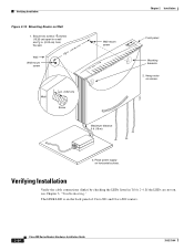
... 1 8 in Table 2-4. Hang router on the back panel of Cisco 801 and Cisco 802 routers. 2-20 Cisco 800 Series Routers Hardware Installation Guide 78-5373-04 The LINK LED is on screws. 3. Verifying Installation Verify the cable connections (links) by checking the LEDs listed in . (0.32 cm) Screw Maximum distance 6 ft (18 m) 11672 Chapter 2 Installation Front panel Mounting brackets 2. If the LEDs are not on horizontal surface. Place power supply on , see Chapter 3, "Troubleshooting." Verifying Installation Figure 2-12 Mounting Router on...
... 1 8 in Table 2-4. Hang router on the back panel of Cisco 801 and Cisco 802 routers. 2-20 Cisco 800 Series Routers Hardware Installation Guide 78-5373-04 The LINK LED is on screws. 3. Verifying Installation Verify the cable connections (links) by checking the LEDs listed in . (0.32 cm) Screw Maximum distance 6 ft (18 m) 11672 Chapter 2 Installation Front panel Mounting brackets 2. If the LEDs are not on horizontal surface. Place power supply on , see Chapter 3, "Troubleshooting." Verifying Installation Figure 2-12 Mounting Router on...

Hardware Installation Guide
Page 47
... No link to an Ethernet device. (On Cisco 801, Cisco 802, and 802 IDSL routers, the LINK LED on server, PC, or workstation. • Run the NIC diagnostic supplied by the vendor to make sure it . • If the problem continues, call your Cisco reseller. Wrong cable. - Improperly connected cable. - Check the cable information in Table 2-2 in Chapter 2, "Installation." • Check specifications in Table B-13 and Table B-14 in Chapter 2, "Installation." • Improperly functioning network interface card...
... No link to an Ethernet device. (On Cisco 801, Cisco 802, and 802 IDSL routers, the LINK LED on server, PC, or workstation. • Run the NIC diagnostic supplied by the vendor to make sure it . • If the problem continues, call your Cisco reseller. Wrong cable. - Improperly connected cable. - Check the cable information in Table 2-2 in Chapter 2, "Installation." • Check specifications in Table B-13 and Table B-14 in Chapter 2, "Installation." • Improperly functioning network interface card...

Hardware Installation Guide
Page 69
Index S S/T interface A-1 safety warnings 2-2 server, connecting 2-9 settings, network devices 2-6 to 2-7 specifications cabling B-6 system B-1 startup problems 3-2 T table mounting 2-18 telephone connecting 2-14, 2-15 ports described 1-2 illustrated 1-5, 1-6 temperature specifications B-1 terminal, connecting 2-17 TO HUB/TO PC button illustrated 1-6 to 1-7 settings 2-6 to 2-20 warnings, installation 2-2 weight specifications B-1 workstation, connecting 2-9 U U interface A-1 United Kingdom master sockets 2-16 78-5373-04 Cisco 800 Series Routers Hardware Installation Guide IN-3 to 2-4 V ...
Index S S/T interface A-1 safety warnings 2-2 server, connecting 2-9 settings, network devices 2-6 to 2-7 specifications cabling B-6 system B-1 startup problems 3-2 T table mounting 2-18 telephone connecting 2-14, 2-15 ports described 1-2 illustrated 1-5, 1-6 temperature specifications B-1 terminal, connecting 2-17 TO HUB/TO PC button illustrated 1-6 to 1-7 settings 2-6 to 2-20 warnings, installation 2-2 weight specifications B-1 workstation, connecting 2-9 U U interface A-1 United Kingdom master sockets 2-16 78-5373-04 Cisco 800 Series Routers Hardware Installation Guide IN-3 to 2-4 V ...


