
Hardware Installation Guide
Page 6
... DC Power Connector 1-21 Cisco RPS Connector 1-22 Console Port 1-23 2 C H A P T E R Installation 2-1 Preparing for Installation 2-1 Warnings 2-1 EMC Regulatory Statements 2-4 U.S.A. 2-4 Taiwan 2-4 Japan 2-5 Korea 2-5 Hungary 2-6 Installation Guidelines 2-6 Verifying Package Contents 2-7 Installing the Switch on a Table or Shelf 2-9 Installing the Switch in a Rack 2-9 Removing Screws from the Switch 2-11 Attaching the Brackets to a Catalyst 2912 XL, 2924C XL...
... DC Power Connector 1-21 Cisco RPS Connector 1-22 Console Port 1-23 2 C H A P T E R Installation 2-1 Preparing for Installation 2-1 Warnings 2-1 EMC Regulatory Statements 2-4 U.S.A. 2-4 Taiwan 2-4 Japan 2-5 Korea 2-5 Hungary 2-6 Installation Guidelines 2-6 Verifying Package Contents 2-7 Installing the Switch on a Table or Shelf 2-9 Installing the Switch in a Rack 2-9 Removing Screws from the Switch 2-11 Attaching the Brackets to a Catalyst 2912 XL, 2924C XL...

Hardware Installation Guide
Page 7
...18 Attaching the Optional Cable Guide 2-19 Installing the Switch on a Wall 2-20 Attaching the Brackets to the Switch 2-21 Mounting the Switch to a Wall 2-22 Powering On the Switch and Running POST 2-24 Connecting to DC Power 2-25 Preparing for Installation 2-25 Grounding the Switch 2-26 Wiring the DC-Input Power Source 2-29... Correcting Module POST Failures 3-2 Diagnosing Problems 3-3 Technical Specifications A-1 Connectors and Cable Specifications B-1 Connector Specifications B-1 10/100 Ports B-1 100BASE-FX Ports B-2 Contents 78-6461-04 Catalyst 2900 Series XL Hardware Installation Guide vii
...18 Attaching the Optional Cable Guide 2-19 Installing the Switch on a Wall 2-20 Attaching the Brackets to the Switch 2-21 Mounting the Switch to a Wall 2-22 Powering On the Switch and Running POST 2-24 Connecting to DC Power 2-25 Preparing for Installation 2-25 Grounding the Switch 2-26 Wiring the DC-Input Power Source 2-29... Correcting Module POST Failures 3-2 Diagnosing Problems 3-3 Technical Specifications A-1 Connectors and Cable Specifications B-1 Connector Specifications B-1 10/100 Ports B-1 100BASE-FX Ports B-2 Contents 78-6461-04 Catalyst 2900 Series XL Hardware Installation Guide vii

Hardware Installation Guide
Page 9
INDEX Class 1 Laser Product Warning C-22 Laser Beam Exposure Warning C-23 No On/Off Switch Warning C-24 Chassis Warning-Rack-Mounting and Servicing C-25 Reinforced Insulation Warning C-29 LAN Connections Only Warning C-30 No Field-Replaceable Units Warning C-31 Installation ... Equipment Warning C-36 Ground Connection Warning C-37 Qualified Personnel Warning C-38 DC Power Disconnection Warning C-39 Exposed Wire Lead Warning C-41 Contents 78-6461-04 Catalyst 2900 Series XL Hardware Installation Guide ix
INDEX Class 1 Laser Product Warning C-22 Laser Beam Exposure Warning C-23 No On/Off Switch Warning C-24 Chassis Warning-Rack-Mounting and Servicing C-25 Reinforced Insulation Warning C-29 LAN Connections Only Warning C-30 No Field-Replaceable Units Warning C-31 Installation ... Equipment Warning C-36 Ground Connection Warning C-37 Qualified Personnel Warning C-38 DC Power Disconnection Warning C-39 Exposed Wire Lead Warning C-41 Contents 78-6461-04 Catalyst 2900 Series XL Hardware Installation Guide ix

Hardware Installation Guide
Page 11
... the networking or computer technician responsible for installing a switch in a rack, on a desk, or on a wall. It describes the physical and performance characteristics of Catalyst 2900 series XL switches. Purpose The Catalyst 2900 Series XL Hardware Installation Guide documents the hardware ...features of the switches, explains how to identify and resolve some of Ethernet and local area ...
... the networking or computer technician responsible for installing a switch in a rack, on a desk, or on a wall. It describes the physical and performance characteristics of Catalyst 2900 series XL switches. Purpose The Catalyst 2900 Series XL Hardware Installation Guide documents the hardware ...features of the switches, explains how to identify and resolve some of Ethernet and local area ...

Hardware Installation Guide
Page 12
Notes, cautions, and warnings use these conventions: • Commands and keywords are in boldface. • Arguments for the switches and the regulatory agency approvals. Notes contain helpful suggestions or references to materials not contained in this guide. Appendix B, "Connectors and Cable Specifications," ..."Technical Specifications," lists the physical and environmental specifications for which you might do something that can be careful. Examples use the following conventions to the switch. Catalyst 2900 Series XL Hardware Installation Guide xii 78-6461-04
Notes, cautions, and warnings use these conventions: • Commands and keywords are in boldface. • Arguments for the switches and the regulatory agency approvals. Notes contain helpful suggestions or references to materials not contained in this guide. Appendix B, "Connectors and Cable Specifications," ..."Technical Specifications," lists the physical and environmental specifications for which you might do something that can be careful. Examples use the following conventions to the switch. Catalyst 2900 Series XL Hardware Installation Guide xii 78-6461-04

Hardware Installation Guide
Page 15
... only in the "Obtaining Documentation" section on page xvi. • Release Notes for the Catalyst 2900 Series XL and Catalyst 3500 Series XL Switches (not orderable but is available on Cisco.com for the latest information. 78-6461-04 Catalyst 2900 Series XL Hardware Installation Guide xv Preface Related Publications ¡Advertencia! Se förklaringar...
... only in the "Obtaining Documentation" section on page xvi. • Release Notes for the Catalyst 2900 Series XL and Catalyst 3500 Series XL Switches (not orderable but is available on Cisco.com for the latest information. 78-6461-04 Catalyst 2900 Series XL Hardware Installation Guide xv Preface Related Publications ¡Advertencia! Se förklaringar...

Hardware Installation Guide
Page 16
... online help (available only from the switch CMS software) • Catalyst 2900 Series XL Hardware Installation Guide (order number DOC-786461=) • Catalyst 3500 Series XL Hardware Installation Guide (order number DOC-786456=) • Catalyst 2900 Series XL Modules Installation Guide (order...1000BASE-T Gigabit Interface Converter Installation Note (not orderable but is available on Cisco.com) • Catalyst GigaStack Gigabit Interface Converter Hardware Installation Guide (order number DOC-786460=) • Cisco LRE CPE Hardware Installation Guide (order number DOC-7811469=) • ...
... online help (available only from the switch CMS software) • Catalyst 2900 Series XL Hardware Installation Guide (order number DOC-786461=) • Catalyst 3500 Series XL Hardware Installation Guide (order number DOC-786456=) • Catalyst 2900 Series XL Modules Installation Guide (order...1000BASE-T Gigabit Interface Converter Installation Note (not orderable but is available on Cisco.com) • Catalyst GigaStack Gigabit Interface Converter Hardware Installation Guide (order number DOC-786460=) • Cisco LRE CPE Hardware Installation Guide (order number DOC-7811469=) • ...

Hardware Installation Guide
Page 21
...switches can connect workstations, Cisco IP Phones, and other network devices such as backbone switches, aggregating 10/100 and Gigabit Ethernet traffic from other switches. The Catalyst 2900 XL switches have these topics that allows an Ethernet network to reach distances up to 4921 feet (1500 meters). The 2900 XL LRE switches... employ Long-Reach Ethernet (LRE), a very-high-data-rate digital subscriber line (VDSL)-based technology that describe the Catalyst 2900 series XL switches, hereafter referred to as the switches. • Switch features, including management ...
...switches can connect workstations, Cisco IP Phones, and other network devices such as backbone switches, aggregating 10/100 and Gigabit Ethernet traffic from other switches. The Catalyst 2900 XL switches have these topics that allows an Ethernet network to reach distances up to 4921 feet (1500 meters). The 2900 XL LRE switches... employ Long-Reach Ethernet (LRE), a very-high-data-rate digital subscriber line (VDSL)-based technology that describe the Catalyst 2900 series XL switches, hereafter referred to as the switches. • Switch features, including management ...

Hardware Installation Guide
Page 22
... • On the Catalyst 2912 LRE XL and 2924 LRE XL switches, up to 24 LRE ports through one RJ-21 connector and hot swapping capability with the Cisco LRE customer premises equipment (CPE) devices • Supports up to 2048 MAC addresses on the Catalyst 2924 XL, 2924C XL..., and 2912 XL switches • Supports up to 8192 MAC addresses on the Catalyst 2924M XL, Catalyst 2924M XL DC and Catalyst 2912MF XL switches Figure 1-1 shows the switch models. Catalyst ...
... • On the Catalyst 2912 LRE XL and 2924 LRE XL switches, up to 24 LRE ports through one RJ-21 connector and hot swapping capability with the Cisco LRE customer premises equipment (CPE) devices • Supports up to 2048 MAC addresses on the Catalyst 2924 XL, 2924C XL..., and 2912 XL switches • Supports up to 8192 MAC addresses on the Catalyst 2924M XL, Catalyst 2924M XL DC and Catalyst 2912MF XL switches Figure 1-1 shows the switch models. Catalyst ...

Hardware Installation Guide
Page 23
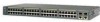
Chapter 1 Product Overview Figure 1-1 Catalyst 2900 Series XL Switches Version Number Description WS-C2912-LRE-XL 4 fixed autosensing 10/100 ports INPUT OUTPUT PWR PWR RESET TEMP FAN 9X 10X 11X 12X 12 LRE ports Cisco RPS 300 WS-C2924-LRE-XL 4 fixed autosensing 10/100 ports 24 LRE ports INPUT OUTPUT PWR PWR... 4 5 100BASE-FX 6 7 8 9 10 11 12 WS-C2924M-XL WS-C2924M-XLEM-DC 24 fixed autosensing 10/100 ports 2 expansion slots 12 MODE 1X 2X 3X Catalyst 2900 SERIES XL 4X 5X 6X 7X 8X 9X 10X 11X 100BaseFX 12X 13X 14X 15X 16X 17X 18X 19X 20X 21X 22X 23X 24X...
Chapter 1 Product Overview Figure 1-1 Catalyst 2900 Series XL Switches Version Number Description WS-C2912-LRE-XL 4 fixed autosensing 10/100 ports INPUT OUTPUT PWR PWR RESET TEMP FAN 9X 10X 11X 12X 12 LRE ports Cisco RPS 300 WS-C2924-LRE-XL 4 fixed autosensing 10/100 ports 24 LRE ports INPUT OUTPUT PWR PWR... 4 5 100BASE-FX 6 7 8 9 10 11 12 WS-C2924M-XL WS-C2924M-XLEM-DC 24 fixed autosensing 10/100 ports 2 expansion slots 12 MODE 1X 2X 3X Catalyst 2900 SERIES XL 4X 5X 6X 7X 8X 9X 10X 11X 100BaseFX 12X 13X 14X 15X 16X 17X 18X 19X 20X 21X 22X 23X 24X...

Hardware Installation Guide
Page 24
... members from the CLI. You can also display network topologies to gather link information and to display switch images to the Catalyst 2900 Series XL and Catalyst 3500 Series XL Software Configuration Guide. You can manage switch configuration settings, performance, security, and collect statistics by using SNMP management applications such as HP OpenView or...
... members from the CLI. You can also display network topologies to gather link information and to display switch images to the Catalyst 2900 Series XL and Catalyst 3500 Series XL Software Configuration Guide. You can manage switch configuration settings, performance, security, and collect statistics by using SNMP management applications such as HP OpenView or...

Hardware Installation Guide
Page 26
...device and advertises its own capabilities. Catalyst 2900 Series XL Hardware Installation Guide 1-6 78-6461-04 The 10/100 ports on the Catalyst 3524-PWR XL switch, refer to the Catalyst 3500 Series XL Hardware Installation Guide. Cisco IP Phones-connected to switches or hubs, use Category 3 and ...4 cables. Unlike the 3524-PWR XL switch, the Catalyst 2900 XL switches do not provide inline power. A ...
...device and advertises its own capabilities. Catalyst 2900 Series XL Hardware Installation Guide 1-6 78-6461-04 The 10/100 ports on the Catalyst 3524-PWR XL switch, refer to the Catalyst 3500 Series XL Hardware Installation Guide. Cisco IP Phones-connected to switches or hubs, use Category 3 and ...4 cables. Unlike the 3524-PWR XL switch, the Catalyst 2900 XL switches do not provide inline power. A ...

Hardware Installation Guide
Page 27
... the patch panel through a private branch exchange (PBX) switch, a Cisco LRE 48 POTS Splitter can hot swap the CPE devices without powering down the switch or disrupting the other switch ports. For information about the Cisco LRE CPE devices, refer to the Catalyst 2900 Series XL and Catalyst 3500 Series XL Software Configuration Guide. For more information...
... the patch panel through a private branch exchange (PBX) switch, a Cisco LRE 48 POTS Splitter can hot swap the CPE devices without powering down the switch or disrupting the other switch ports. For information about the Cisco LRE CPE devices, refer to the Catalyst 2900 Series XL and Catalyst 3500 Series XL Software Configuration Guide. For more information...

Hardware Installation Guide
Page 28
...X2914-XL WS-X2914-XL-V WS-X2922-XL WS-X2922-XL-V WS-X2924-XL-V Catalyst 2900 Series XL Hardware Installation Guide 1-8 78-6461-04 Due to the proprietary nature of digital PBX switches, some digital PBX switch services use the 0 to the PSTN. Module Slots The module slots (see Figure 1-2)...Panel Description Chapter 1 Product Overview (PSTN). For more information about the Cisco LRE 48 POTS Splitter (PS-1M-LRE-48), refer to other switch ports and is not needed, and the switch can connect directly to digital PBX switches that use frequencies above 700 kHz do not work when sharing a line ...
...X2914-XL WS-X2914-XL-V WS-X2922-XL WS-X2922-XL-V WS-X2924-XL-V Catalyst 2900 Series XL Hardware Installation Guide 1-8 78-6461-04 Due to the proprietary nature of digital PBX switches, some digital PBX switch services use the 0 to the PSTN. Module Slots The module slots (see Figure 1-2)...Panel Description Chapter 1 Product Overview (PSTN). For more information about the Cisco LRE 48 POTS Splitter (PS-1M-LRE-48), refer to other switch ports and is not needed, and the switch can connect directly to digital PBX switches that use frequencies above 700 kHz do not work when sharing a line ...

Hardware Installation Guide
Page 29
...the information provided by restarting that you use the switch LEDs to the Release Notes for Catalyst 2900 series XL switches. For a complete list and the minimum software release required, refer to monitor switch activity and its performance. These modules automatically configure ...addresses. A power-on expansion modules for the Catalyst 2900 Series XL and Catalyst 3500 Series XL Switches. If you insert them in a 2924M XL or Catalyst 2912MF XL switch (both supporting 8192 MAC addresses), the module fails POST. Catalyst 2900 Series XL Hardware Installation Guide 1-9 Figure ...
...the information provided by restarting that you use the switch LEDs to the Release Notes for Catalyst 2900 series XL switches. For a complete list and the minimum software release required, refer to monitor switch activity and its performance. These modules automatically configure ...addresses. A power-on expansion modules for the Catalyst 2900 Series XL and Catalyst 3500 Series XL Switches. If you insert them in a 2924M XL or Catalyst 2912MF XL switch (both supporting 8192 MAC addresses), the module fails POST. Catalyst 2900 Series XL Hardware Installation Guide 1-9 Figure ...

Hardware Installation Guide
Page 30
...Mode RPS button LED 47288 1-10 Catalyst 2900 Series XL Hardware Installation Guide 78-6461-04 The Catalyst 2900 Series XL and Catalyst 3500 Series XL Software Configuration Guide describes how to use CMS to manage standalone or individual switches and how to use cluster management... software to manage switch clusters]. Front-Panel Description Chapter 1 Product...
...Mode RPS button LED 47288 1-10 Catalyst 2900 Series XL Hardware Installation Guide 78-6461-04 The Catalyst 2900 Series XL and Catalyst 3500 Series XL Software Configuration Guide describes how to use CMS to manage standalone or individual switches and how to use cluster management... software to manage switch clusters]. Front-Panel Description Chapter 1 Product...

Hardware Installation Guide
Page 32
System is receiving power but is receiving power and functioning properly. Front-Panel Description Figure 1-7 Catalyst 2912 LRE XL and 2924 LRE XL LEDs 10/100 port LEDs Chapter 1 Product Overview SYSTEM RPS MODE LRE STAT DUPLX SPEED Mode button 1X ... 1-2 lists the LED colors and their meanings. For information on the System LED colors during POST, see the "Powering On the Switch and Running POST" section on page 2-24. 1-12 Catalyst 2900 Series XL Hardware Installation Guide 78-6461-04 Table 1-2 System LED Color Off Green Amber System Status System is operating...
System is receiving power but is receiving power and functioning properly. Front-Panel Description Figure 1-7 Catalyst 2912 LRE XL and 2924 LRE XL LEDs 10/100 port LEDs Chapter 1 Product Overview SYSTEM RPS MODE LRE STAT DUPLX SPEED Mode button 1X ... 1-2 lists the LED colors and their meanings. For information on the System LED colors during POST, see the "Powering On the Switch and Running POST" section on page 2-24. 1-12 Catalyst 2900 Series XL Hardware Installation Guide 78-6461-04 Table 1-2 System LED Color Off Green Amber System Status System is operating...

Hardware Installation Guide
Page 33
...could have failed. • The fan in standby mode. Chapter 1 Product Overview Front-Panel Description RPS LED The Catalyst 2912 LRE XL and Catalyst 2924 LRE XL switches use the Cisco RPS 600 (model PWR600-AC-RPS). Figure 1-8 RPS LED on the RPS puts it is off or is not...RPS is providing power to another device (redundancy has been allocated to the appropriate switch documentation for redundant power system (RPS) descriptions specific for the switch. All other Catalyst 2900 XL and Catalyst 3500 XL switches use the Cisco RPS 300 (model PWR300-AC-RPS-N1). Table 1-3 RPS LED on page ...
...could have failed. • The fan in standby mode. Chapter 1 Product Overview Front-Panel Description RPS LED The Catalyst 2912 LRE XL and Catalyst 2924 LRE XL switches use the Cisco RPS 600 (model PWR600-AC-RPS). Figure 1-8 RPS LED on the RPS puts it is off or is not...RPS is providing power to another device (redundancy has been allocated to the appropriate switch documentation for redundant power system (RPS) descriptions specific for the switch. All other Catalyst 2900 XL and Catalyst 3500 XL switches use the Cisco RPS 300 (model PWR300-AC-RPS-N1). Table 1-3 RPS LED on page ...

Hardware Installation Guide
Page 34
...the RPS fan could have a port LED. When you change a mode, press the Mode button until the desired mode is the default mode. Contact Cisco Systems. The internal power supply in a fault condition. Port LEDs and Modes Each of the 10/100, 100BASE-FX, and LRE ports and module slots... 1 Product Overview Table 1-3 RPS LED on the Catalyst 2912 LRE XL and 2924 LRE XL Switches (continued) Color Solid amber Blinking amber RPS Status The RPS is in standby mode or in a switch has failed, and the RPS is providing power to the switch (redundancy has been allocated to this device). The ...
...the RPS fan could have a port LED. When you change a mode, press the Mode button until the desired mode is the default mode. Contact Cisco Systems. The internal power supply in a fault condition. Port LEDs and Modes Each of the 10/100, 100BASE-FX, and LRE ports and module slots... 1 Product Overview Table 1-3 RPS LED on the Catalyst 2912 LRE XL and 2924 LRE XL Switches (continued) Color Solid amber Blinking amber RPS Status The RPS is in standby mode or in a switch has failed, and the RPS is providing power to the switch (redundancy has been allocated to this device). The ...

Hardware Installation Guide
Page 35
... the remote CPE. Note When the LRE mode is active, the 10/100 switch ports on all Catalyst 2900 XL and Catalyst 3500 XL switches except the Catalyst 2912 LRE XL and Catalyst 2924 LRE XL switches. Ethernet link status of the LRE ports on these switches only. The default setting is half duplex. Default mode on the...
... the remote CPE. Note When the LRE mode is active, the 10/100 switch ports on all Catalyst 2900 XL and Catalyst 3500 XL switches except the Catalyst 2912 LRE XL and Catalyst 2924 LRE XL switches. Ethernet link status of the LRE ports on these switches only. The default setting is half duplex. Default mode on the...


