
Hardware Installation Guide
Page 6
... DC Power Connector 1-21 Cisco RPS Connector 1-22 Console Port 1-23 2 C H A P T E R Installation 2-1 Preparing for Installation 2-1 Warnings 2-1 EMC Regulatory Statements 2-4 U.S.A. 2-4 Taiwan 2-4 Japan 2-5 Korea 2-5 Hungary 2-6 Installation Guidelines 2-6 Verifying Package Contents 2-7 Installing the Switch on a Table or Shelf 2-9 Installing the Switch in a Rack 2-9 Removing Screws from the Switch 2-11 Attaching the Brackets to a Catalyst 2912 XL, 2924C XL...
... DC Power Connector 1-21 Cisco RPS Connector 1-22 Console Port 1-23 2 C H A P T E R Installation 2-1 Preparing for Installation 2-1 Warnings 2-1 EMC Regulatory Statements 2-4 U.S.A. 2-4 Taiwan 2-4 Japan 2-5 Korea 2-5 Hungary 2-6 Installation Guidelines 2-6 Verifying Package Contents 2-7 Installing the Switch on a Table or Shelf 2-9 Installing the Switch in a Rack 2-9 Removing Screws from the Switch 2-11 Attaching the Brackets to a Catalyst 2912 XL, 2924C XL...

Hardware Installation Guide
Page 7
...18 Attaching the Optional Cable Guide 2-19 Installing the Switch on a Wall 2-20 Attaching the Brackets to the Switch 2-21 Mounting the Switch to a Wall 2-22 Powering On the Switch and Running POST 2-24 Connecting to DC Power 2-25 Preparing for Installation 2-25 Grounding the Switch 2-26 Wiring the DC-Input Power Source 2-29 ...Correcting Module POST Failures 3-2 Diagnosing Problems 3-3 Technical Specifications A-1 Connectors and Cable Specifications B-1 Connector Specifications B-1 10/100 Ports B-1 100BASE-FX Ports B-2 Contents 78-6461-04 Catalyst 2900 Series XL Hardware Installation Guide vii
...18 Attaching the Optional Cable Guide 2-19 Installing the Switch on a Wall 2-20 Attaching the Brackets to the Switch 2-21 Mounting the Switch to a Wall 2-22 Powering On the Switch and Running POST 2-24 Connecting to DC Power 2-25 Preparing for Installation 2-25 Grounding the Switch 2-26 Wiring the DC-Input Power Source 2-29 ...Correcting Module POST Failures 3-2 Diagnosing Problems 3-3 Technical Specifications A-1 Connectors and Cable Specifications B-1 Connector Specifications B-1 10/100 Ports B-1 100BASE-FX Ports B-2 Contents 78-6461-04 Catalyst 2900 Series XL Hardware Installation Guide vii

Hardware Installation Guide
Page 9
INDEX Class 1 Laser Product Warning C-22 Laser Beam Exposure Warning C-23 No On/Off Switch Warning C-24 Chassis Warning-Rack-Mounting and Servicing C-25 Reinforced Insulation Warning C-29 LAN Connections Only Warning C-30 No Field-Replaceable Units Warning C-31 Installation Warning C-32 ... Equipment Warning C-36 Ground Connection Warning C-37 Qualified Personnel Warning C-38 DC Power Disconnection Warning C-39 Exposed Wire Lead Warning C-41 Contents 78-6461-04 Catalyst 2900 Series XL Hardware Installation Guide ix
INDEX Class 1 Laser Product Warning C-22 Laser Beam Exposure Warning C-23 No On/Off Switch Warning C-24 Chassis Warning-Rack-Mounting and Servicing C-25 Reinforced Insulation Warning C-29 LAN Connections Only Warning C-30 No Field-Replaceable Units Warning C-31 Installation Warning C-32 ... Equipment Warning C-36 Ground Connection Warning C-37 Qualified Personnel Warning C-38 DC Power Disconnection Warning C-39 Exposed Wire Lead Warning C-41 Contents 78-6461-04 Catalyst 2900 Series XL Hardware Installation Guide ix

Hardware Installation Guide
Page 11
...and terminology of Catalyst 2900 series XL switches. Chapter 2, "Installation," provides the procedures for installing and configuring a Catalyst 2900 series XL switch. Preface Audience This guide is organized into the following chapters: Chapter 1, "Product Overview," summarizes the switch features and ...describes the ports, the standards they support, and the LEDs. Purpose The Catalyst 2900 Series XL Hardware Installation Guide documents the hardware features of Ethernet and...
...and terminology of Catalyst 2900 series XL switches. Chapter 2, "Installation," provides the procedures for installing and configuring a Catalyst 2900 series XL switch. Preface Audience This guide is organized into the following chapters: Chapter 1, "Product Overview," summarizes the switch features and ...describes the ports, the standards they support, and the LEDs. Purpose The Catalyst 2900 Series XL Hardware Installation Guide documents the hardware features of Ethernet and...

Hardware Installation Guide
Page 12
... and information: Command descriptions use these conventions: • Commands and keywords are in boldface. • Arguments for the switches and the regulatory agency approvals. Catalyst 2900 Series XL Hardware Installation Guide xii 78-6461-04 In this manual. Examples use these conventions: • Terminal sessions...; Nonprinting characters, such as passwords or tabs, are in angle brackets (< >). Notes contain helpful suggestions or references to the switch. Caution Means reader be used to connect to materials not contained in various languages of data.
... and information: Command descriptions use these conventions: • Commands and keywords are in boldface. • Arguments for the switches and the regulatory agency approvals. Catalyst 2900 Series XL Hardware Installation Guide xii 78-6461-04 In this manual. Examples use these conventions: • Terminal sessions...; Nonprinting characters, such as passwords or tabs, are in angle brackets (< >). Notes contain helpful suggestions or references to the switch. Caution Means reader be used to connect to materials not contained in various languages of data.

Hardware Installation Guide
Page 15
...som kan leda till personskada. Before installing, configuring, or upgrading the switch, refer to the release notes on Cisco.com) Note Switch requirements and procedures for the latest information. 78-6461-04 Catalyst 2900 Series XL Hardware Installation Guide xv Denna varningssymbol signalerar fara. Innan...the "Obtaining Documentation" section on page xvi. • Release Notes for the Catalyst 2900 Series XL and Catalyst 3500 Series XL Switches (not orderable but is available on Cisco.com for initial configurations and software upgrades tend to change and therefore appear only ...
...som kan leda till personskada. Before installing, configuring, or upgrading the switch, refer to the release notes on Cisco.com) Note Switch requirements and procedures for the latest information. 78-6461-04 Catalyst 2900 Series XL Hardware Installation Guide xv Denna varningssymbol signalerar fara. Innan...the "Obtaining Documentation" section on page xvi. • Release Notes for the Catalyst 2900 Series XL and Catalyst 3500 Series XL Switches (not orderable but is available on Cisco.com for initial configurations and software upgrades tend to change and therefore appear only ...

Hardware Installation Guide
Page 16
... online help (available only from the switch CMS software) • Catalyst 2900 Series XL Hardware Installation Guide (order number DOC-786461=) • Catalyst 3500 Series XL Hardware Installation Guide (order number DOC-786456=) • Catalyst 2900 Series XL Modules Installation Guide (order...1000BASE-T Gigabit Interface Converter Installation Note (not orderable but is available on Cisco.com) • Catalyst GigaStack Gigabit Interface Converter Hardware Installation Guide (order number DOC-786460=) • Cisco LRE CPE Hardware Installation Guide (order number DOC-7811469=) • ...
... online help (available only from the switch CMS software) • Catalyst 2900 Series XL Hardware Installation Guide (order number DOC-786461=) • Catalyst 3500 Series XL Hardware Installation Guide (order number DOC-786456=) • Catalyst 2900 Series XL Modules Installation Guide (order...1000BASE-T Gigabit Interface Converter Installation Note (not orderable but is available on Cisco.com) • Catalyst GigaStack Gigabit Interface Converter Hardware Installation Guide (order number DOC-786460=) • Cisco LRE CPE Hardware Installation Guide (order number DOC-7811469=) • ...

Hardware Installation Guide
Page 21
...; Descriptions of the front and rear panels • Descriptions of the LEDs Features The switches are stackable 10/100 Ethernet switches to the destination port 78-6461-04 Catalyst 2900 Series XL Hardware Installation Guide 1-1 The switches can connect workstations, Cisco IP Phones, and other network devices such as servers, routers, and other network devices...
...; Descriptions of the front and rear panels • Descriptions of the LEDs Features The switches are stackable 10/100 Ethernet switches to the destination port 78-6461-04 Catalyst 2900 Series XL Hardware Installation Guide 1-1 The switches can connect workstations, Cisco IP Phones, and other network devices such as servers, routers, and other network devices...

Hardware Installation Guide
Page 22
...transfer mode (ATM) modules • On the Catalyst 2924M XL DC switch, a direct current (DC) power converter • On the Catalyst 2912 LRE XL and 2924 LRE XL switches, up to 24 LRE ports through one RJ-21 connector and hot swapping capability with the Cisco LRE customer premises equipment (CPE) devices •...; Supports up to 2048 MAC addresses on the Catalyst 2924 XL, 2924C XL, and 2912 XL switches • Supports up to...
...transfer mode (ATM) modules • On the Catalyst 2924M XL DC switch, a direct current (DC) power converter • On the Catalyst 2912 LRE XL and 2924 LRE XL switches, up to 24 LRE ports through one RJ-21 connector and hot swapping capability with the Cisco LRE customer premises equipment (CPE) devices •...; Supports up to 2048 MAC addresses on the Catalyst 2924 XL, 2924C XL, and 2912 XL switches • Supports up to...

Hardware Installation Guide
Page 23
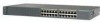
Chapter 1 Product Overview Figure 1-1 Catalyst 2900 Series XL Switches Version Number Description WS-C2912-LRE-XL 4 fixed autosensing 10/100 ports INPUT OUTPUT PWR PWR RESET TEMP FAN 9X 10X 11X 12X 12 LRE ports Cisco RPS 300 WS-C2924-LRE-XL 4 fixed autosensing 10/100 ports 24 LRE ports INPUT OUTPUT PWR PWR ...RESET TEMP FAN 9X 10X 11X 12X Cisco RPS 300 WS-C2912-XL 12 fixed autosensing 10/100 ports MODE 1X 2X 3X 4X 5X 6X 7X 8X 9X 10X 10BaseT/100BASE-TX 11X 12X Catalyst 2900 SERIES XL WS-C2924C...
Chapter 1 Product Overview Figure 1-1 Catalyst 2900 Series XL Switches Version Number Description WS-C2912-LRE-XL 4 fixed autosensing 10/100 ports INPUT OUTPUT PWR PWR RESET TEMP FAN 9X 10X 11X 12X 12 LRE ports Cisco RPS 300 WS-C2924-LRE-XL 4 fixed autosensing 10/100 ports 24 LRE ports INPUT OUTPUT PWR PWR ...RESET TEMP FAN 9X 10X 11X 12X Cisco RPS 300 WS-C2912-XL 12 fixed autosensing 10/100 ports MODE 1X 2X 3X 4X 5X 6X 7X 8X 9X 10X 10BaseT/100BASE-TX 11X 12X Catalyst 2900 SERIES XL WS-C2924C...

Hardware Installation Guide
Page 24
... management applications such as HP OpenView or SunNet Manager. CMS is enhanced to the Catalyst 2900 Series XL and Catalyst 3500 Series XL Software Configuration Guide. For more information about CMS, the CLI, and SNMP refer to support desktop-switching features. Using CMS, you can also display network topologies to gather link information...
... management applications such as HP OpenView or SunNet Manager. CMS is enhanced to the Catalyst 2900 Series XL and Catalyst 3500 Series XL Software Configuration Guide. For more information about CMS, the CLI, and SNMP refer to support desktop-switching features. Using CMS, you can also display network topologies to gather link information...

Hardware Installation Guide
Page 26
... 5 cabling Note A Category 5 cable is required for Cisco IP Phones and per-port priority override. The 10/100 ports on the Catalyst 3524-PWR XL switch, refer to the Catalyst 2900 Series XL and Catalyst 3500 Series XL Software Configuration Guide for more info on the Catalyst 2900 XL switches provide protocol support for 100BASE-TX traffic...
... 5 cabling Note A Category 5 cable is required for Cisco IP Phones and per-port priority override. The 10/100 ports on the Catalyst 3524-PWR XL switch, refer to the Catalyst 2900 Series XL and Catalyst 3500 Series XL Software Configuration Guide for more info on the Catalyst 2900 XL switches provide protocol support for 100BASE-TX traffic...

Hardware Installation Guide
Page 27
... patch panel through a private branch exchange (PBX) switch, a Cisco LRE 48 POTS Splitter can be over distances of up to 1352 feet (412 meters). • If the switch port and the port on the same Catalyst 2900 LRE XL switch, and you can hot swap the CPE devices without...4921 feet (1500 meters). The PBX routes voice traffic to the switch and private branch exchange (PBX) switch or Public-Switched Telephone Network (PSTN). The link between the switch and the attached device can be up to 24 Cisco LRE customer premises equipment (CPE) devices though structured or unstructured wiring,...
... patch panel through a private branch exchange (PBX) switch, a Cisco LRE 48 POTS Splitter can be over distances of up to 1352 feet (412 meters). • If the switch port and the port on the same Catalyst 2900 LRE XL switch, and you can hot swap the CPE devices without...4921 feet (1500 meters). The PBX routes voice traffic to the switch and private branch exchange (PBX) switch or Public-Switched Telephone Network (PSTN). The link between the switch and the attached device can be up to 24 Cisco LRE customer premises equipment (CPE) devices though structured or unstructured wiring,...

Hardware Installation Guide
Page 28
...share lines with LRE signals. Each module port is internally switched to other switch ports and is not needed, and the switch can connect directly to the PSTN. For more information about homologated POTS splitters, contact your Cisco sales representative. Table 1-1 lists the modules that use ... For more information about the Cisco LRE 48 POTS Splitter (PS-1M-LRE-48), refer to a telephone network is not required, a splitter is managed through the switch management interfaces. Note If a connection to the Installation Notes for the Catalyst 2900 XL hot-swappable modules...
...share lines with LRE signals. Each module port is internally switched to other switch ports and is not needed, and the switch can connect directly to the PSTN. For more information about homologated POTS splitters, contact your Cisco sales representative. Table 1-1 lists the modules that use ... For more information about the Cisco LRE 48 POTS Splitter (PS-1M-LRE-48), refer to a telephone network is not required, a splitter is managed through the switch management interfaces. Note If a connection to the Installation Notes for the Catalyst 2900 XL hot-swappable modules...

Hardware Installation Guide
Page 29
... when you install one of the LEDs and the Mode button that the module is reduced to the Release Notes for the Catalyst 2900 Series XL and Catalyst 3500 Series XL Switches. Note Modules WS-X2914-XL and WS-X2922-XL support 2048 MAC addresses. After the restart, the...WS-X2971-XL WS-X2972-XL WS-X2951-XL WS-X2961-XL 1. You can use to monitor switch activity and its performance. The Ethernet Gigabit module supports several Gigabit Interface Converter (GBIC) devices. Catalyst 2900 Series XL Hardware Installation Guide 1-9 For a complete list and the minimum software release required, ...
... when you install one of the LEDs and the Mode button that the module is reduced to the Release Notes for the Catalyst 2900 Series XL and Catalyst 3500 Series XL Switches. Note Modules WS-X2914-XL and WS-X2922-XL support 2048 MAC addresses. After the restart, the...WS-X2971-XL WS-X2972-XL WS-X2951-XL WS-X2961-XL 1. You can use to monitor switch activity and its performance. The Ethernet Gigabit module supports several Gigabit Interface Converter (GBIC) devices. Catalyst 2900 Series XL Hardware Installation Guide 1-9 For a complete list and the minimum software release required, ...

Hardware Installation Guide
Page 30
... the utilization meter (UTL) are visible on the Cluster Management Suite (CMS) window and, if the switch is a cluster member, on the CMS Cluster Manager window. The Catalyst 2900 Series XL and Catalyst 3500 Series XL Software Configuration Guide describes how to use CMS to manage standalone or individual... switches and how to use cluster management software to manage switch clusters]. Figure 1-5 Catalyst 2912 XL, 2924 XL, and 2924C XL LEDs 10/100 port LEDs System LED Port mode LEDs MODE 1X 2X...
... the utilization meter (UTL) are visible on the Cluster Management Suite (CMS) window and, if the switch is a cluster member, on the CMS Cluster Manager window. The Catalyst 2900 Series XL and Catalyst 3500 Series XL Software Configuration Guide describes how to use CMS to manage standalone or individual... switches and how to use cluster management software to manage switch clusters]. Figure 1-5 Catalyst 2912 XL, 2924 XL, and 2924C XL LEDs 10/100 port LEDs System LED Port mode LEDs MODE 1X 2X...

Hardware Installation Guide
Page 32
For information on the System LED colors during POST, see the "Powering On the Switch and Running POST" section on page 2-24. 1-12 Catalyst 2900 Series XL Hardware Installation Guide 78-6461-04 Table 1-2 System LED Color Off Green Amber System Status System is operating normally. System is not ...
For information on the System LED colors during POST, see the "Powering On the Switch and Running POST" section on page 2-24. 1-12 Catalyst 2900 Series XL Hardware Installation Guide 78-6461-04 Table 1-2 System LED Color Off Green Amber System Status System is operating normally. System is not ...

Hardware Installation Guide
Page 33
... button on page 1-22. RPS is connected and ready to the appropriate switch documentation for redundant power system (RPS) descriptions specific for the switch. All other Catalyst 2900 XL and Catalyst 3500 XL switches use the Cisco RPS 300 (model PWR300-AC-RPS-N1). For more information see the... "Cisco RPS Connector" section on the RPS puts it restarts. If the switch power supply fails, the switch powers down and after...
... button on page 1-22. RPS is connected and ready to the appropriate switch documentation for redundant power system (RPS) descriptions specific for the switch. All other Catalyst 2900 XL and Catalyst 3500 XL switches use the Cisco RPS 300 (model PWR300-AC-RPS-N1). For more information see the... "Cisco RPS Connector" section on the RPS puts it restarts. If the switch power supply fails, the switch powers down and after...

Hardware Installation Guide
Page 34
...Cisco Systems. The internal power supply in use by the switch. (See Figure 1-8.) The port duplex mode: full duplex or half duplex, and default modes: • 10/100 ports: auto • 100BaseFX ports: auto • Gigabit ports: auto The port operating speed: 10 or 100 Mbps. 1-14 Catalyst ...2900 Series XL Hardware Installation Guide 78-6461-04 These port LEDs, as a group or individually, display information about the switch and about the individual ports. The port modes (Table 1-4 and Table 1-5) determine ...
...Cisco Systems. The internal power supply in use by the switch. (See Figure 1-8.) The port duplex mode: full duplex or half duplex, and default modes: • 10/100 ports: auto • 100BaseFX ports: auto • Gigabit ports: auto The port operating speed: 10 or 100 Mbps. 1-14 Catalyst ...2900 Series XL Hardware Installation Guide 78-6461-04 These port LEDs, as a group or individually, display information about the switch and about the individual ports. The port modes (Table 1-4 and Table 1-5) determine ...

Hardware Installation Guide
Page 35
... LRE XL continue to show Ethernet link status. Default mode on all Catalyst 2900 XL and Catalyst 3500 XL switches except the Catalyst 2912 LRE XL and Catalyst 2924 LRE XL switches. Default mode on these switches only. Note When the LRE mode is half duplex. The port duplex mode: full duplex or... half duplex. The default setting is active, the 10/100 switch ports on the Catalyst 2912 LRE XL and Catalyst 2924 LRE XL switches. The default setting is auto. 78-6461-04 Catalyst 2900 Series XL Hardware Installation Guide 1-15 The port operating speed: 10 or 100 Mbps...
... LRE XL continue to show Ethernet link status. Default mode on all Catalyst 2900 XL and Catalyst 3500 XL switches except the Catalyst 2912 LRE XL and Catalyst 2924 LRE XL switches. Default mode on these switches only. Note When the LRE mode is half duplex. The port duplex mode: full duplex or... half duplex. The default setting is active, the 10/100 switch ports on the Catalyst 2912 LRE XL and Catalyst 2924 LRE XL switches. The default setting is auto. 78-6461-04 Catalyst 2900 Series XL Hardware Installation Guide 1-15 The port operating speed: 10 or 100 Mbps...


