
User Guide
Page 2
...Cisco 2501 and CPA2501 routers. Figure 1-1 to Figure 1-7 show the rear panels of the publication, one model number will apply to the interfaces listed in Table 1-1, the routers include the following hardware features: • Dynamic random-access memory (DRAM) for main memory and shared memory • Nonvolatile random-access memory (NVRAM) for storing configuration... Features Note Throughout the remainder of the router models discussed in this publication. 1-2 Router Installation and Configuration Guide For example, references to the model 2501 router will be used in text references.
...Cisco 2501 and CPA2501 routers. Figure 1-1 to Figure 1-7 show the rear panels of the publication, one model number will apply to the interfaces listed in Table 1-1, the routers include the following hardware features: • Dynamic random-access memory (DRAM) for main memory and shared memory • Nonvolatile random-access memory (NVRAM) for storing configuration... Features Note Throughout the remainder of the router models discussed in this publication. 1-2 Router Installation and Configuration Guide For example, references to the model 2501 router will be used in text references.

User Guide
Page 4
...) Synchronous serial ports (DB-60) Console port (RJ-45) On/off Power switch ISDN BRI port (RJ-45) Auxiliary port (RJ-45) Figure 1-4 Model 2504 Router Rear Panel Token Ring Synchronous ISDN System LED serial LEDs BRI LED OK LED Token Ring port (DB-9) Synchronous serial ports (DB-60) Console port...
...) Synchronous serial ports (DB-60) Console port (RJ-45) On/off Power switch ISDN BRI port (RJ-45) Auxiliary port (RJ-45) Figure 1-4 Model 2504 Router Rear Panel Token Ring Synchronous ISDN System LED serial LEDs BRI LED OK LED Token Ring port (DB-9) Synchronous serial ports (DB-60) Console port...

User Guide
Page 6
... Synchronous serial ports (DB-60) Console port (RJ-45) On/off Power switch Auxiliary port (RJ-45) System Specifications The system specifications of the routers are listed in . (4.44 x 44.45 x 26.82 cm), one rack unit 10 lb (4.5 kg) 100 to 240 VAC 1.2 to 0.6A...Hz 40W (maximum), 135.5 Btus1/hr 40W, 40 to 72 VDC 1.5 to 1.0A 40W (maximum), 135.5 Btus/hr 20-MHz Motorola 68EC030 1-6 Router Installation and Configuration Guide Table 1-2 System Specifications Description Dimensions (H x W x D) Weight Input voltage, AC power supply Current Frequency Power dissipation Input voltage, DC power ...
... Synchronous serial ports (DB-60) Console port (RJ-45) On/off Power switch Auxiliary port (RJ-45) System Specifications The system specifications of the routers are listed in . (4.44 x 44.45 x 26.82 cm), one rack unit 10 lb (4.5 kg) 100 to 240 VAC 1.2 to 0.6A...Hz 40W (maximum), 135.5 Btus1/hr 40W, 40 to 72 VDC 1.5 to 1.0A 40W (maximum), 135.5 Btus/hr 20-MHz Motorola 68EC030 1-6 Router Installation and Configuration Guide Table 1-2 System Specifications Description Dimensions (H x W x D) Weight Input voltage, AC power supply Current Frequency Power dissipation Input voltage, DC power ...

User Guide
Page 8
... additional content and services. SMARTnet customers and partners can access CCO in the following terminal settings: VT100 emulation; Cisco Connection Online Note If you can access Cisco Connection Online (CCO) as hyperlinks to 14.4 kbps. 1-8 Router Installation and Configuration Guide CCO services include product information, software updates, release notes, technical tips, the Bug Navigator...
... additional content and services. SMARTnet customers and partners can access CCO in the following terminal settings: VT100 emulation; Cisco Connection Online Note If you can access Cisco Connection Online (CCO) as hyperlinks to 14.4 kbps. 1-8 Router Installation and Configuration Guide CCO services include product information, software updates, release notes, technical tips, the Bug Navigator...

User Guide
Page 10
Ordering Documentation 1-10 Router Installation and Configuration Guide
Ordering Documentation 1-10 Router Installation and Configuration Guide
Getting Started Guide
Page 2
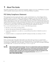
... number provided at the end of the hazards involved with the limits for a Class B digital device, pursuant to Part 15 of the Cisco 2500 Series Wireless Controllers. A warning symbol precedes each warning to locate its translation in a particular installation. However, there is no guarantee that... in this guide are applicable to the entire guide. 1 About This Guide This guide is designed to help you install and minimally configure your Cisco 2504 Wireless Controller (2504 controller), which the receiver is connected. • Consult the dealer or an experienced radio/TV technician for ...
... number provided at the end of the hazards involved with the limits for a Class B digital device, pursuant to Part 15 of the Cisco 2500 Series Wireless Controllers. A warning symbol precedes each warning to locate its translation in a particular installation. However, there is no guarantee that... in this guide are applicable to the entire guide. 1 About This Guide This guide is designed to help you install and minimally configure your Cisco 2504 Wireless Controller (2504 controller), which the receiver is connected. • Consult the dealer or an experienced radio/TV technician for ...
Getting Started Guide
Page 5
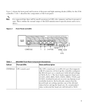
Figure 2 Front Panel and LEDs 282249 CONSOLE CONSOLE CISCO 2500 Series WIRELESS CONTROLLER RESET Model 2504 1 2 3 4 PWR SYS ALM RESET 1 2 3-4 POE PWR ALM SYS Table 1 Callout WLC2504 Front Panel Component Descriptions Port and LEDs ..., 38400, 57600, and 115200. A default baud-rate recovery mechanism is an RS-232 port that there will default to unit. At boot-up the controller configures the RS-232 port as a console port with default settings of the ports and light-emitting diodes (LEDs) for the 2504 controller. Figure 2 shows the...
Figure 2 Front Panel and LEDs 282249 CONSOLE CONSOLE CISCO 2500 Series WIRELESS CONTROLLER RESET Model 2504 1 2 3 4 PWR SYS ALM RESET 1 2 3-4 POE PWR ALM SYS Table 1 Callout WLC2504 Front Panel Component Descriptions Port and LEDs ..., 38400, 57600, and 115200. A default baud-rate recovery mechanism is an RS-232 port that there will default to unit. At boot-up the controller configures the RS-232 port as a console port with default settings of the ports and light-emitting diodes (LEDs) for the 2504 controller. Figure 2 shows the...

Getting Started Guide
Page 6
... access point devices to I2C address 0x40/41 (0100 000r/w). This port is designed so that 1500 VAC rms isolation (per the 802.3 specification) is configured to these ports. do so over -Ethernet (POE) ports The Gigabit POE ports are PoE only ports; LED description: • Green or Blinking Green-Link...
... access point devices to I2C address 0x40/41 (0100 000r/w). This port is designed so that 1500 VAC rms isolation (per the 802.3 specification) is configured to these ports. do so over -Ethernet (POE) ports The Gigabit POE ports are PoE only ports; LED description: • Green or Blinking Green-Link...
Getting Started Guide
Page 9
... representative. Package Contents Each 2504 controller package contains the following items: • One Cisco 2504 Wireless Controller. • One Power supply and power cord (power cord option configurable). • Cisco 2504 Wireless Controller software pre-loaded on the controller (software option configurable). • Optional licenses will be pre-installed on controller at factory, if...
... representative. Package Contents Each 2504 controller package contains the following items: • One Cisco 2504 Wireless Controller. • One Power supply and power cord (power cord option configurable). • Cisco 2504 Wireless Controller software pre-loaded on the controller (software option configurable). • Optional licenses will be pre-installed on controller at factory, if...

Getting Started Guide
Page 10
...management interface netmask address, such as 255.255.255.0. • A management interface default router IP address, such as 10.40.0.5. • A VLAN identifier if the management interface...8226; Whether or not to 24 printable ASCII characters. Initial System Configuration Information Obtain the following initial configuration parameters from clients, either Yes or No. - The system name... 1.1.1.1, used by all Cisco wireless controller Layer 3 security and mobility managers). • A Cisco wireless controller mobility or RF group name, such as the Cisco WCS because Cisco WCS and third-party...
...management interface netmask address, such as 255.255.255.0. • A management interface default router IP address, such as 10.40.0.5. • A VLAN identifier if the management interface...8226; Whether or not to 24 printable ASCII characters. Initial System Configuration Information Obtain the following initial configuration parameters from clients, either Yes or No. - The system name... 1.1.1.1, used by all Cisco wireless controller Layer 3 security and mobility managers). • A Cisco wireless controller mobility or RF group name, such as the Cisco WCS because Cisco WCS and third-party...

Getting Started Guide
Page 11
... • Make sure that the controller is more secure and reliable if you can reach the controller and all cables attached to the Cisco Wireless LAN Controller Configuration Guide for this installation. This guide is available at least 4 in a secure equipment room or wiring closet. Leave at... cisco.com. • Status of the 802.11a, 802.11b, 802.11g, or 802.11n networks, either enabled or disabled. • Status of ...
... • Make sure that the controller is more secure and reliable if you can reach the controller and all cables attached to the Cisco Wireless LAN Controller Configuration Guide for this installation. This guide is available at least 4 in a secure equipment room or wiring closet. Leave at... cisco.com. • Status of the 802.11a, 802.11b, 802.11g, or 802.11n networks, either enabled or disabled. • Status of ...

Getting Started Guide
Page 13
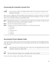
...tasks to complete the installation: • Connecting the Controller Console Port • Securing the Power Adapter Cable • Connecting to the Network For configuration instructions about using the CLI setup program, see the "Running the Bootup Script and Power-On Self Test" section on a wall using an ...before beginning installation. Note Allow 3 inches of the 2504 controller as shown in Figure 5 with 19-inch rack mounting brackets and hardware from Cisco. Failure to use the correct hardware or to follow these steps: Step 1 Attach the 19-inch brackets to each side of space around...
...tasks to complete the installation: • Connecting the Controller Console Port • Securing the Power Adapter Cable • Connecting to the Network For configuration instructions about using the CLI setup program, see the "Running the Bootup Script and Power-On Self Test" section on a wall using an ...before beginning installation. Note Allow 3 inches of the 2504 controller as shown in Figure 5 with 19-inch rack mounting brackets and hardware from Cisco. Failure to use the correct hardware or to follow these steps: Step 1 Attach the 19-inch brackets to each side of space around...

Getting Started Guide
Page 15
... the following tasks to complete the installation: • Connecting the Controller Console Port • Securing the Power Adapter Cable • Connecting to the Network For configuration instructions about using mounting screws, always mount the controller with the front panel facing down ) 2 #10-32 flat head screws 3 Wall mounting screws Step 3 Step...
... the following tasks to complete the installation: • Connecting the Controller Console Port • Securing the Power Adapter Cable • Connecting to the Network For configuration instructions about using mounting screws, always mount the controller with the front panel facing down ) 2 #10-32 flat head screws 3 Wall mounting screws Step 3 Step...
Getting Started Guide
Page 18
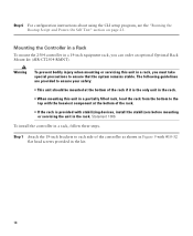
... #10-32 flat head screws provided in a 19-inch equipment rack, you can order an optional Optional Rack Mount kit (AIR-CT2504-RMNT). Step 6 For configuration instructions about using the CLI setup program, see the "Running the Bootup Script and Power-On Self Test" section on page 23. Mounting the Controller...
... #10-32 flat head screws provided in a 19-inch equipment rack, you can order an optional Optional Rack Mount kit (AIR-CT2504-RMNT). Step 6 For configuration instructions about using the CLI setup program, see the "Running the Bootup Script and Power-On Self Test" section on page 23. Mounting the Controller...

Getting Started Guide
Page 20
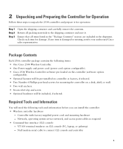
Figure 10 Mounting the Controller in a 19-Inch Rack 1 282086 1 #10-32 pan-head screws or #12-24 slotted head screws Step 3 Step 4 After the controller is mounted in the rack, perform the following tasks to complete the installation: • Connecting the Controller Console Port • Securing the Power Adapter Cable • Connecting to the Network For configuration instructions about using the CLI setup program, see the "Running the Bootup Script and Power-On Self Test" section on page 23. 20
Figure 10 Mounting the Controller in a 19-Inch Rack 1 282086 1 #10-32 pan-head screws or #12-24 slotted head screws Step 3 Step 4 After the controller is mounted in the rack, perform the following tasks to complete the installation: • Connecting the Controller Console Port • Securing the Power Adapter Cable • Connecting to the Network For configuration instructions about using the CLI setup program, see the "Running the Bootup Script and Power-On Self Test" section on page 23. 20
Getting Started Guide
Page 21
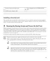
...so will damage the controller. Start the PC terminal emulation program. Note The Cisco 2106 power adapter is not compatible with the cable. Caution If the relief clip is pulled or if the power adapter falls. Configure the terminal emulation program for basic operations, you can be damaged if the ...power cable is not installed, the power connector can configure the 2504 controller for the following parameters: • 9600 baud • 8 data bits • No flow control • 1 stop bit • No ...
...so will damage the controller. Start the PC terminal emulation program. Note The Cisco 2106 power adapter is not compatible with the cable. Caution If the relief clip is pulled or if the power adapter falls. Configure the terminal emulation program for basic operations, you can be damaged if the ...power cable is not installed, the power connector can configure the 2504 controller for the following parameters: • 9600 baud • 8 data bits • No flow control • 1 stop bit • No ...
Getting Started Guide
Page 23
... lights. Note If you plug the controller into an AC power source, the bootup script initializes the system, verifies the hardware configuration, loads its microcode into memory, verifies its stored configurations. You can install an optional customer-supplied cable lock, such as described in the "Connecting the Controller Console Port" section on...
... lights. Note If you plug the controller into an AC power source, the bootup script initializes the system, verifies the hardware configuration, loads its microcode into memory, verifies its stored configurations. You can install an optional customer-supplied cable lock, such as described in the "Connecting the Controller Console Port" section on...
Getting Started Guide
Page 24
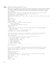
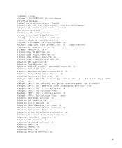
The bootup script displays operating system software initialization (code download and POST verification) and basic configuration as shown in the following menu Boot Loader Menu 1. done Network: octeth0', octeth1, octeth2, octeth3 ' - Active interface E - Type: Hard Disk - Run ...Boot Loader Version 1.0.15 (Built on Nov 23 2010 at 07:51:36 by cisco) Board Revision 0.0 (SN: PSJ143302MT, Type: AIR-CT2504-K9) (P) Verifying boot loader integrity... Run primary image (7.0.114.76) - Clear configuration 5. Manually update images Enter selection: If you did not press Esc, the boot...
The bootup script displays operating system software initialization (code download and POST verification) and basic configuration as shown in the following menu Boot Loader Menu 1. done Network: octeth0', octeth1, octeth2, octeth3 ' - Active interface E - Type: Hard Disk - Run ...Boot Loader Version 1.0.15 (Built on Nov 23 2010 at 07:51:36 by cisco) Board Revision 0.0 (SN: PSJ143302MT, Type: AIR-CT2504-K9) (P) Verifying boot loader integrity... Run primary image (7.0.114.76) - Clear configuration 5. Manually update images Enter selection: If you did not press Esc, the boot...
Getting Started Guide
Page 25
... DP Heartbeat : ok Fastpath CPU00: Starting Fastpath Application. XML config selected Validating XML configuration octeon_device_init: found 1 DPs /dev/fpga: No such device or address readCPUConfigData: cardid 0x6060001 Cisco is a trademark of cores(2) Fastpath CPU00: Init MBUF size: 1856, Subsequent MBUF ...ok Starting Licensing Services: ok Starting LWAPP: ok Starting CAPWAP: ok Starting LOCP: ok Starting Security Services: ok 25 Num of Cisco Systems, Inc. compress = none ifconfig: SIOCGIFFLAGS: No such device Detecting Hardware ... Installing ether-pow driver - 0x6008 starting pid...
... DP Heartbeat : ok Fastpath CPU00: Starting Fastpath Application. XML config selected Validating XML configuration octeon_device_init: found 1 DPs /dev/fpga: No such device or address readCPUConfigData: cardid 0x6060001 Cisco is a trademark of cores(2) Fastpath CPU00: Init MBUF size: 1856, Subsequent MBUF ...ok Starting Licensing Services: ok Starting LWAPP: ok Starting CAPWAP: ok Starting LOCP: ok Starting Security Services: ok 25 Num of Cisco Systems, Inc. compress = none ifconfig: SIOCGIFFLAGS: No such device Detecting Hardware ... Installing ether-pow driver - 0x6008 starting pid...
Getting Started Guide
Page 27
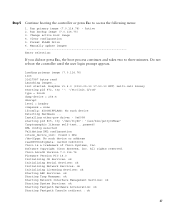
...: SIOCGIFFLAGS: No such device Detecting Hardware ... XML config selected Validating XML configuration octeon_device_init: found 1 DPs /dev/fpga: No such device or address readCPUConfigData: cardid 0x6060001 Cisco is a trademark of Cisco Systems, Inc. Run backup image (7.0.114.75) 3. Manually update images ...access the following menu: 1. All rights reserved. Run primary image (7.0.114.76) - Format FLASH Drive 6. Active 2. Cisco AireOS Version 7.0.114.76 Firmware Version PIC 14.0 Initializing OS Services: ok Initializing Serial Services: ok Initializing Network Services: ...
...: SIOCGIFFLAGS: No such device Detecting Hardware ... XML config selected Validating XML configuration octeon_device_init: found 1 DPs /dev/fpga: No such device or address readCPUConfigData: cardid 0x6060001 Cisco is a trademark of Cisco Systems, Inc. Run backup image (7.0.114.75) 3. Manually update images ...access the following menu: 1. All rights reserved. Run primary image (7.0.114.76) - Format FLASH Drive 6. Active 2. Cisco AireOS Version 7.0.114.76 Firmware Version PIC 14.0 Initializing OS Services: ok Initializing Serial Services: ok Initializing Network Services: ...

