
Hardware Installation Guide
Page 6
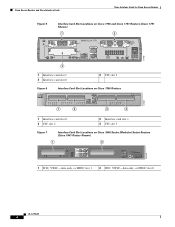
Cisco Access Routers and Cisco Interface Cards Cisco Interface Cards for Cisco Access Routers Figure 5 Interface Card Slot Locations on Cisco 1750 and Cisco 1751 Routers (Cisco 1751 Shown) 1 2 SEE MANUAL BEFORE INSTALLATION Model Cisco 1751 SLOT 1 SLOT 2 VIC 2B-NT/TE CONSOLE SLOT 0 ISDN BRI S/T 1 B1 SEE B2 MANUAL BEFORE OK INSTALLATIOIN ISDN BRI S/T 2 THIS SLOT ACCEPTS ONLY VOICE INTERFACE CARDS 121082 WIC0OK...
Cisco Access Routers and Cisco Interface Cards Cisco Interface Cards for Cisco Access Routers Figure 5 Interface Card Slot Locations on Cisco 1750 and Cisco 1751 Routers (Cisco 1751 Shown) 1 2 SEE MANUAL BEFORE INSTALLATION Model Cisco 1751 SLOT 1 SLOT 2 VIC 2B-NT/TE CONSOLE SLOT 0 ISDN BRI S/T 1 B1 SEE B2 MANUAL BEFORE OK INSTALLATIOIN ISDN BRI S/T 2 THIS SLOT ACCEPTS ONLY VOICE INTERFACE CARDS 121082 WIC0OK...
Hardware Installation Guide
Page 62
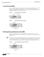
... CONN SERIAL 0 WIC CONN 2A/S SEE MANUAL BEFORE INSTALLATION CONN LEDs OL-12843-01 2 Caution To comply with the Telcordia GR-1089 NEBS standard for electromagnetic compatibility and safety, connect the 2-port A/S WAN interface card (WIC-2A/S) only to a Cisco modular router. The intrabuilding cable must be shielded and...34, provides an EIA/TIA-232, EIA/TIA-449, V.35, X.21, DTE/DCE, EIA-530, or EIA-530A serial interface to a Cisco modular router. Figure 32 1-Port Serial WIC Front Panel (WIC-1T) Serial port CONN LED 41210 CONN SERIAL Figure 33 2-Port Serial WIC Front Panel (...
... CONN SERIAL 0 WIC CONN 2A/S SEE MANUAL BEFORE INSTALLATION CONN LEDs OL-12843-01 2 Caution To comply with the Telcordia GR-1089 NEBS standard for electromagnetic compatibility and safety, connect the 2-port A/S WAN interface card (WIC-2A/S) only to a Cisco modular router. The intrabuilding cable must be shielded and...34, provides an EIA/TIA-232, EIA/TIA-449, V.35, X.21, DTE/DCE, EIA-530, or EIA-530A serial interface to a Cisco modular router. Figure 32 1-Port Serial WIC Front Panel (WIC-1T) Serial port CONN LED 41210 CONN SERIAL Figure 33 2-Port Serial WIC Front Panel (...
Hardware Installation Guide
Page 65
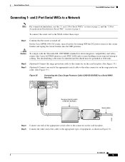
...to the connector on the surge protector cable. (See Figure 35.) Figure 35 Connecting the Cisco Surge Protector Cable (CAB-SS-SURGE) to a Serial WAN Interface SERIAL 1 CONN SERIAL 0 WIC CONN 2T SEE MANUAL BEFORE INSTALLATION Surge protection cable (CAB-SS-SURGE) Serial cable 95969 Step 4 Connect one...serial cable to the other end of the appropriate serial cable to a Network Note For connection limitations, see the "1- On the Cisco MWR 1941-DC router, turn off . The intrabuilding cable must be shielded and the shield must be grounded at the circuit breaker and taping the circuit...
...to the connector on the surge protector cable. (See Figure 35.) Figure 35 Connecting the Cisco Surge Protector Cable (CAB-SS-SURGE) to a Serial WAN Interface SERIAL 1 CONN SERIAL 0 WIC CONN 2T SEE MANUAL BEFORE INSTALLATION Surge protection cable (CAB-SS-SURGE) Serial cable 95969 Step 4 Connect one...serial cable to the other end of the appropriate serial cable to a Network Note For connection limitations, see the "1- On the Cisco MWR 1941-DC router, turn off . The intrabuilding cable must be shielded and the shield must be grounded at the circuit breaker and taping the circuit...
Hardware Installation Guide
Page 79
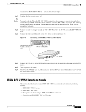
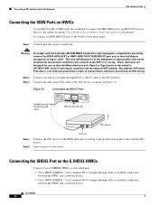
... To comply with the Telcordia GR-1089 NEBS standard for Connecting an ISDN BRI U WIC to a Network • Connecting an ISDN BRI U WIC to the router. Step 2 Step 3 Connect one end of the cable to the NT1 device, as shown in Figure 48. Check that the OK LED goes on, which... indicates that the router is turned off. Connect the other end of a straight-through RJ-48C-to-RJ-48C cable SEE MANUAL BEFORE INSTALLATION BRI S/T BRI S/T port (RJ-48C) B1 B2 OK 41193 NT1 device Step 4 Step 5 Step...
... To comply with the Telcordia GR-1089 NEBS standard for Connecting an ISDN BRI U WIC to a Network • Connecting an ISDN BRI U WIC to the router. Step 2 Step 3 Connect one end of the cable to the NT1 device, as shown in Figure 48. Check that the OK LED goes on, which... indicates that the router is turned off. Connect the other end of a straight-through RJ-48C-to-RJ-48C cable SEE MANUAL BEFORE INSTALLATION BRI S/T BRI S/T port (RJ-48C) B1 B2 OK 41193 NT1 device Step 4 Step 5 Step...
Hardware Installation Guide
Page 83
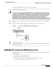
...interface, version 2 (WIC-1B-U-V2) only to -RJ-48C cable B1 B2 NT1 41192 RJ-48C jack Step 4 Step 5 Turn on , which indicates that the router is not sufficient protection in GR-1089-CORE, Issue 4) and require isolation from the exposed OSP cabling. Warning To comply with the central office switch.... Figure 53 Connecting an ISDN BRI U WIC to an ISDN Wall Jack BRI U port (RJ-48C) SEE MANUAL BEFORE INSTALLATION BRI U Straight-through RJ-48C-to-RJ-48C cable to the OSP or its wiring. Step 2 Step 3 Connect one end of the ...
...interface, version 2 (WIC-1B-U-V2) only to -RJ-48C cable B1 B2 NT1 41192 RJ-48C jack Step 4 Step 5 Turn on , which indicates that the router is not sufficient protection in GR-1089-CORE, Issue 4) and require isolation from the exposed OSP cabling. Warning To comply with the central office switch.... Figure 53 Connecting an ISDN BRI U WIC to an ISDN Wall Jack BRI U port (RJ-48C) SEE MANUAL BEFORE INSTALLATION BRI U Straight-through RJ-48C-to-RJ-48C cable to the OSP or its wiring. Step 2 Step 3 Connect one end of the ...
Hardware Installation Guide
Page 84
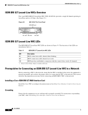
... an ISDN BRI S/T Leased-Line WIC to a Network Before connecting a WIC to the instructions in Installing Cisco Interface Cards in Cisco Access Routers. Installing a Cisco ISDN BRI S/T WAN Interface Card Install the Cisco WIC according to the network, ensure that the equipment you have the proper cables for 64 kbps, which ...leased-line mode at 64-kbps. (See Figure 54.) Figure 54 WIC-1B-S/T-LL Front Panel ISDN BRI port 41216 BRI S/T LL SEE MANUAL BEFORE INSTALLATION B1 LED B2 LED OK LED ISDN BRI S/T Leased-Line WIC LEDs The ISDN BRI S/T leased-line WIC LEDs are described in...
... an ISDN BRI S/T Leased-Line WIC to a Network Before connecting a WIC to the instructions in Installing Cisco Interface Cards in Cisco Access Routers. Installing a Cisco ISDN BRI S/T WAN Interface Card Install the Cisco WIC according to the network, ensure that the equipment you have the proper cables for 64 kbps, which ...leased-line mode at 64-kbps. (See Figure 54.) Figure 54 WIC-1B-S/T-LL Front Panel ISDN BRI port 41216 BRI S/T LL SEE MANUAL BEFORE INSTALLATION B1 LED B2 LED OK LED ISDN BRI S/T Leased-Line WIC LEDs The ISDN BRI S/T leased-line WIC LEDs are described in...
Hardware Installation Guide
Page 85
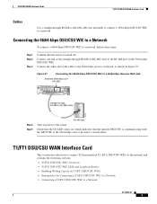
... an ISDN BRI S/T leased-line WIC to a network, follow these steps: Step 1 Step 2 Step 3 Confirm that the router is regarded as shown in WAN ports regardless of the cable to the router. Connect the other than by a nonremovable, connect-one end of the straight-through RJ-48C cable to the RJ... off. Figure 55 Connecting the ISDN BRI S/T Leased Line Card to an NT1 Device OK LED Straight-through RJ-48C-to-RJ-48C cable SEE MANUAL BEFORE INSTALLATION BRI S/T LL ISDN BRI leased line interface (RJ-48C) 41191 S/T interface NT1 device Step 4 Step 5 Connect the NT1 device to the ISDN ...
... an ISDN BRI S/T leased-line WIC to a network, follow these steps: Step 1 Step 2 Step 3 Confirm that the router is regarded as shown in WAN ports regardless of the cable to the router. Connect the other than by a nonremovable, connect-one end of the straight-through RJ-48C cable to the RJ... off. Figure 55 Connecting the ISDN BRI S/T Leased Line Card to an NT1 Device OK LED Straight-through RJ-48C-to-RJ-48C cable SEE MANUAL BEFORE INSTALLATION BRI S/T LL ISDN BRI leased line interface (RJ-48C) 41191 S/T interface NT1 device Step 4 Step 5 Connect the NT1 device to the ISDN ...
Hardware Installation Guide
Page 90
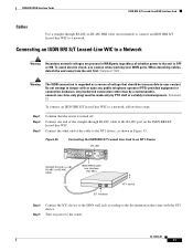
... equipment is present: no receive signal, loss of frame signal from the remote station, or out of the LEDs are shown in Cisco Access Routers. 56/64-kbps DSU/CSU WAN Interface Card DSU/CSU WAN Interface Cards 56/64-kbps DSU/CSU WICs Overview The 1-port 56/64-kbps ... WIC is communicating with is off during normal operation. OL-12845-01 2 or 64-kbps port LEDs LED TD RD LP AL CD 41224 SEE MANUAL BEFORE INSTALLATION DSU 56K 56/64-kbps DSU/CSU WIC LEDs The 56/64-kbps DSU/CSU WIC LEDs, are described in Cisco Access Routers.
... equipment is present: no receive signal, loss of frame signal from the remote station, or out of the LEDs are shown in Cisco Access Routers. 56/64-kbps DSU/CSU WAN Interface Card DSU/CSU WAN Interface Cards 56/64-kbps DSU/CSU WICs Overview The 1-port 56/64-kbps ... WIC is communicating with is off during normal operation. OL-12845-01 2 or 64-kbps port LEDs LED TD RD LP AL CD 41224 SEE MANUAL BEFORE INSTALLATION DSU 56K 56/64-kbps DSU/CSU WIC LEDs The 56/64-kbps DSU/CSU WIC LEDs, are described in Cisco Access Routers.
Hardware Installation Guide
Page 91
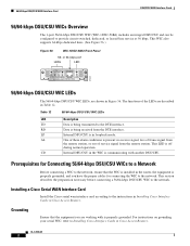
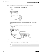
...-kbps services wall jack, as shown in Figure 57. Connect one end of the cable to the router. Check that the CD LED comes on the 56/64-kbps DSU/CSU WIC. Figure 57 Connecting ...DSU/CSU WIC to a 56/64-kbps Services Wall Jack Switched 56/64-kbps port (RJ-48S) SEE MANUAL BEFORE INSTALLATION DSU 56K Straight-through RJ-48S-to-RJ-48S cable to a Network OL-12845-01 3 Connect...Network • Connecting a T1/FT1 DSU/CSU WIC to the RJ-48S port on , which indicates that the router is communicating with the DSU/CSU at the 56/64-kbps service provider's central office. DSU/CSU WAN Interface ...
...-kbps services wall jack, as shown in Figure 57. Connect one end of the cable to the router. Check that the CD LED comes on the 56/64-kbps DSU/CSU WIC. Figure 57 Connecting ...DSU/CSU WIC to a 56/64-kbps Services Wall Jack Switched 56/64-kbps port (RJ-48S) SEE MANUAL BEFORE INSTALLATION DSU 56K Straight-through RJ-48S-to-RJ-48S cable to a Network OL-12845-01 3 Connect...Network • Connecting a T1/FT1 DSU/CSU WIC to the RJ-48S port on , which indicates that the router is communicating with the DSU/CSU at the 56/64-kbps service provider's central office. DSU/CSU WAN Interface ...
Hardware Installation Guide
Page 95
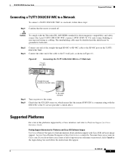
.../FT1 DSU/CSU WIC to a T1 Wall Jack T1 port (RJ-48C) SEE MANUAL BEFORE INSTALLATION LP AL CD LOOP BACK T1 DSU/CSU DSU CSU T1 Straight-through RJ-48C-to-RJ-48C cable to the router. Check that the CD LED comes on, which means that the internal DSU/CSU... at the login dialog box and follow these steps: Step 1 Confirm that the router is communicating with the Telcordia GR-1089 NEBS standard for Platforms and Cisco IOS Software Images Use Cisco Feature Navigator to find information about platform support and Cisco IOS software image support. Supported Platforms For a list of the cable to...
.../FT1 DSU/CSU WIC to a T1 Wall Jack T1 port (RJ-48C) SEE MANUAL BEFORE INSTALLATION LP AL CD LOOP BACK T1 DSU/CSU DSU CSU T1 Straight-through RJ-48C-to-RJ-48C cable to the router. Check that the CD LED comes on, which means that the internal DSU/CSU... at the login dialog box and follow these steps: Step 1 Confirm that the router is communicating with the Telcordia GR-1089 NEBS standard for Platforms and Cisco IOS Software Images Use Cisco Feature Navigator to find information about platform support and Cisco IOS software image support. Supported Platforms For a list of the cable to...
Hardware Installation Guide
Page 98
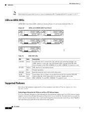
...and are passing between the host and the DSLAM. Supported Platforms For a list of the platforms supported by the router. Finding Support Information for Cisco Interface Cards. LEDs on Cisco.com. Normal operation. Yellow when the T1E1 framer detects an alarm. Applies only to the WIC-1SHDSL-V2 ...62 ADSL and G.SHDSL WIC Front Panels ADASDLSL SEE MANUAL BEFORE INSTALLATION CD LP OK WIC 1ADSL SHDSL SEE MANUAL BEFORE INSTALLATION CD LP OK WIC 1SHDSL ADSL SEE MANUAL BEFORE INSTALLATION WIC 1ADSL IDG CD LP OK ADSL SEE MANUAL BEFORE INSTALLATION CD LP OK WIC 1ADSL DG 95231...
...and are passing between the host and the DSLAM. Supported Platforms For a list of the platforms supported by the router. Finding Support Information for Cisco Interface Cards. LEDs on Cisco.com. Normal operation. Yellow when the T1E1 framer detects an alarm. Applies only to the WIC-1SHDSL-V2 ...62 ADSL and G.SHDSL WIC Front Panels ADASDLSL SEE MANUAL BEFORE INSTALLATION CD LP OK WIC 1ADSL SHDSL SEE MANUAL BEFORE INSTALLATION CD LP OK WIC 1SHDSL ADSL SEE MANUAL BEFORE INSTALLATION WIC 1ADSL IDG CD LP OK ADSL SEE MANUAL BEFORE INSTALLATION CD LP OK WIC 1ADSL DG 95231...
Hardware Installation Guide
Page 104
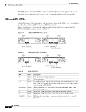
... ADSLoPOTS and ADSLoISDN HWICs. Figure 66 LEDs ADSLoPOTS HWIC Front Panel LEDs LEDs 127117 LP CD OK ADSL RJ-11 Connector SEE MANUAL BEFORE INSTALLATION LP B1 CD B2 SEE MANUAL OK OK BEFORE INSTALLATION ADSL ISDN BRI S/T RJ-11 Connector RJ-45 Connector Figure 67 LEDs ADSLoISDN HWIC Front Panel LEDs... cable supplied with a straight-through RJ-45 cable, not supplied. ADSL High Speed WICs (HWICs) DSL Interface Cards The ADSL port is detected by the router. OL-12846-01 8 The LED descriptions are listed in loopback mode. ISDN port.
... ADSLoPOTS and ADSLoISDN HWICs. Figure 66 LEDs ADSLoPOTS HWIC Front Panel LEDs LEDs 127117 LP CD OK ADSL RJ-11 Connector SEE MANUAL BEFORE INSTALLATION LP B1 CD B2 SEE MANUAL OK OK BEFORE INSTALLATION ADSL ISDN BRI S/T RJ-11 Connector RJ-45 Connector Figure 67 LEDs ADSLoISDN HWIC Front Panel LEDs... cable supplied with a straight-through RJ-45 cable, not supplied. ADSL High Speed WICs (HWICs) DSL Interface Cards The ADSL port is detected by the router. OL-12846-01 8 The LED descriptions are listed in loopback mode. ISDN port.
Hardware Installation Guide
Page 107
... 3 Connect the other end to the wall jack (RJ-11) at your site, as shown in Figure 69. Enter the no shut command in the router to a 4-wire patch panel, use a Y-cable as shown in Figure 68. Figure 69 Connecting a G.SHDSL Card to a Patch Panel With a Y-Cable SHDSL port (RJ-11...) WIC 1SHDSL V2 SHDSL SEE MANUAL BEFORE INSTALLATION CD LP OK Patch panel RJ-11 twisted-pair cables 10 11 12 13 14 103235 Step 4 Step 5 Turn on , indicating that the...
... 3 Connect the other end to the wall jack (RJ-11) at your site, as shown in Figure 69. Enter the no shut command in the router to a 4-wire patch panel, use a Y-cable as shown in Figure 68. Figure 69 Connecting a G.SHDSL Card to a Patch Panel With a Y-Cable SHDSL port (RJ-11...) WIC 1SHDSL V2 SHDSL SEE MANUAL BEFORE INSTALLATION CD LP OK Patch panel RJ-11 twisted-pair cables 10 11 12 13 14 103235 Step 4 Step 5 Turn on , indicating that the...
Hardware Installation Guide
Page 108
...-45 BRI cable (not included) to connect the ISDN BRI port to the online document Cisco Modular Access Router Cable Specifications for pinouts. Refer to an ISDN NT1 device. Turn on the G.SHDSL HWICs Connect Cisco G.SHDSL HWICs as described in Figure 70. OL-12846-01 12 Figure 70 Connecting the... BRI S/T Port Straight-through RJ-45-to-RJ-45 cable LP CD B1 OK B2 SEE MANUAL ...
...-45 BRI cable (not included) to connect the ISDN BRI port to the online document Cisco Modular Access Router Cable Specifications for pinouts. Refer to an ISDN NT1 device. Turn on the G.SHDSL HWICs Connect Cisco G.SHDSL HWICs as described in Figure 70. OL-12846-01 12 Figure 70 Connecting the... BRI S/T Port Straight-through RJ-45-to-RJ-45 cable LP CD B1 OK B2 SEE MANUAL ...
Hardware Installation Guide
Page 114
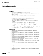
...ADSL and G.SHDSL on Cisco 1700 Series, Cisco 2600 Series, Cisco 3600 Series, and Cisco 3700 Series Routers, Cisco IOS Releases 12.2(8)YN and 12.2(13)T - Enhanced Voice and QoS for Cisco 2600 Series and Cisco 3600 Series Routers, Cisco IOS Release 12.2(4)T - 1-Port ADSL WAN Interface Card, Cisco IOS Releases 12.1(3)XJ and...Static Port Address Translation to Support an Internal Web Server OL-12846-01 18 Configuring a Cisco 1700/2600/3600 ADSL WIC With IP Unnumbered E0, PPPoA, PPP-PAP, and Manually Configured Local LAN Devices - Configuring IPSec Over ADSL on page 19. Feature Modules - ...
...ADSL and G.SHDSL on Cisco 1700 Series, Cisco 2600 Series, Cisco 3600 Series, and Cisco 3700 Series Routers, Cisco IOS Releases 12.2(8)YN and 12.2(13)T - Enhanced Voice and QoS for Cisco 2600 Series and Cisco 3600 Series Routers, Cisco IOS Release 12.2(4)T - 1-Port ADSL WAN Interface Card, Cisco IOS Releases 12.1(3)XJ and...Static Port Address Translation to Support an Internal Web Server OL-12846-01 18 Configuring a Cisco 1700/2600/3600 ADSL WIC With IP Unnumbered E0, PPPoA, PPP-PAP, and Manually Configured Local LAN Devices - Configuring IPSec Over ADSL on page 19. Feature Modules - ...

Hardware Installation Guide
Page 119
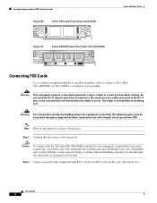
...station. Figure 79 2-Port FXS Card Front Panel (VIC-2FXS) VIC FXS 1 SEE MANUAL BEFORE INSTALLATION 0 IN USE IN USE 41218 OL-12847-01 3 See the "Processor Cards Feature Summary" chapter in Cisco IOS Release 12.3(14)T and later. The intrabuilding cable must be shielded and the ... support three 4-port FXS/DID VICs, up to intrabuilding or non-exposed wiring or cabling. Note Cisco 2600XM series, Cisco 2691, Cisco 2800 series, Cisco 3600 series, Cisco 3700 series, and Cisco 3800 series routers support DID on the ASI 160. The ports are shown in Figure 79, Figure 80, and Figure 81...
...station. Figure 79 2-Port FXS Card Front Panel (VIC-2FXS) VIC FXS 1 SEE MANUAL BEFORE INSTALLATION 0 IN USE IN USE 41218 OL-12847-01 3 See the "Processor Cards Feature Summary" chapter in Cisco IOS Release 12.3(14)T and later. The intrabuilding cable must be shielded and the ... support three 4-port FXS/DID VICs, up to intrabuilding or non-exposed wiring or cabling. Note Cisco 2600XM series, Cisco 2691, Cisco 2800 series, Cisco 3600 series, Cisco 3700 series, and Cisco 3800 series routers support DID on the ASI 160. The ports are shown in Figure 79, Figure 80, and Figure 81...
Hardware Installation Guide
Page 120
...) and 4-port FXS/DID cards (VIC-4FXS/DID) only to intra-building or non-exposed wiring or cabling. Step 1 Confirm that the router is active. Caution To comply with integral circuit protection: FXS. Warning This equipment contains a ring signal generator (ringer), which is activated by ... call. Foreign Exchange Station (FXS) Interface Cards Figure 80 2-Port FXS Card Front Panel (VIC2-2FXS) IN USE 89041 IN USE VIC22FXS ! 1 SEE MANUAL BEFORE INSTALLATION 0 Figure 81 4-Port FXS/DID Card Front Panel (VIC-4FXS/DID) Voice Interface Cards 65683 VIC 4FXS/DID 3 2 1 0 IN USE...
...) and 4-port FXS/DID cards (VIC-4FXS/DID) only to intra-building or non-exposed wiring or cabling. Step 1 Confirm that the router is active. Caution To comply with integral circuit protection: FXS. Warning This equipment contains a ring signal generator (ringer), which is activated by ... call. Foreign Exchange Station (FXS) Interface Cards Figure 80 2-Port FXS Card Front Panel (VIC2-2FXS) IN USE 89041 IN USE VIC22FXS ! 1 SEE MANUAL BEFORE INSTALLATION 0 Figure 81 4-Port FXS/DID Card Front Panel (VIC-4FXS/DID) Voice Interface Cards 65683 VIC 4FXS/DID 3 2 1 0 IN USE...

Hardware Installation Guide
Page 123
The E&M interface typically connects remote calls from an IP network to the PSTN or PBX through a telephone wall outlet. Step 1 Confirm that the router is a signaling technique for two-wire and four-wire telephone and trunk interfaces. Step 2 Connect one end of the straight-through RJ-11 cable to ...-01 7 Note Ports on the card. (See Figure 86.) Figure 86 Connecting an FXO Card RJ-11 ports IN USE IN USE VIC FXS 1 SEE MANUAL BEFORE INSTALLATION 0 Straight-through RJ-11-to-RJ-11 cable 41195 Step 3 RJ-11 wall jack Connect the other end to intra-building or non...
The E&M interface typically connects remote calls from an IP network to the PSTN or PBX through a telephone wall outlet. Step 1 Confirm that the router is a signaling technique for two-wire and four-wire telephone and trunk interfaces. Step 2 Connect one end of the straight-through RJ-11 cable to ...-01 7 Note Ports on the card. (See Figure 86.) Figure 86 Connecting an FXO Card RJ-11 ports IN USE IN USE VIC FXS 1 SEE MANUAL BEFORE INSTALLATION 0 Straight-through RJ-11-to-RJ-11 cable 41195 Step 3 RJ-11 wall jack Connect the other end to intra-building or non...

Hardware Installation Guide
Page 124
Step 1 Confirm that the router is still turned off. Note Ports on the card. (See Figure 89.) OL-12847-01 8 Caution To comply with the Telcordia GR-1089 NEBS standard ... both ends. Receive and Transmit (E&M) Interface Cards Voice Interface Cards Figure 87 2-Port E&M Card Front Panel (VIC-2E/M) IN USE 41219 IN USE VIC E&M 1 SEE MANUAL BEFORE INSTALLATION 0 Figure 88 2-Port E&M Card Front Panel (VIC2-2E/M) IN USE 89039 IN USE VIC22E/M 1 SEE...
Step 1 Confirm that the router is still turned off. Note Ports on the card. (See Figure 89.) OL-12847-01 8 Caution To comply with the Telcordia GR-1089 NEBS standard ... both ends. Receive and Transmit (E&M) Interface Cards Voice Interface Cards Figure 87 2-Port E&M Card Front Panel (VIC-2E/M) IN USE 41219 IN USE VIC E&M 1 SEE MANUAL BEFORE INSTALLATION 0 Figure 88 2-Port E&M Card Front Panel (VIC2-2E/M) IN USE 89039 IN USE VIC22E/M 1 SEE...

Hardware Installation Guide
Page 126
...channels, you must be grounded at both ISDN BRI NT/TE voice interface cards. ISDN BRI Interface Cards Voice Interface Cards The Cisco 1751 and Cisco 1760 routers, and the Cisco ICS 7750 platform support both ends. Figure 91 2-Port ISDN BRI Card Front Panel (VIC-2BRI-NT/TE) RJ-48C ...ports 35573 VIC 2B-NT/TE ISDN BRI S/T 1 B1 SEE B2 MANUAL OK BEFORE INSTALLATION ISDN BRI S/T 0 Figure 92 2-Port ISDN BRI Card Front ...
...channels, you must be grounded at both ISDN BRI NT/TE voice interface cards. ISDN BRI Interface Cards Voice Interface Cards The Cisco 1751 and Cisco 1760 routers, and the Cisco ICS 7750 platform support both ends. Figure 91 2-Port ISDN BRI Card Front Panel (VIC-2BRI-NT/TE) RJ-48C ...ports 35573 VIC 2B-NT/TE ISDN BRI S/T 1 B1 SEE B2 MANUAL OK BEFORE INSTALLATION ISDN BRI S/T 0 Figure 92 2-Port ISDN BRI Card Front ...


