

Users Manual - English
Page 9
.... Avoid setting up in a location where the temperature stays between 50-90.5°F(10-32.5°C). Do not select a place that might disturb the power supply. This will cause a disruption of cordless phones. SETUP & PREPARATION BEFORE USE Choosing a Suitable Place for your fax machine to electrical outlets on a flat, stable surface... Your Fax Machine Use the following list as speakers or the base units of power and can wipe out information from vibration and shocks. Ch. 1 3550-US-5.0 SETUP & PREPARATION BEFORE USE 1.
.... Avoid setting up in a location where the temperature stays between 50-90.5°F(10-32.5°C). Do not select a place that might disturb the power supply. This will cause a disruption of cordless phones. SETUP & PREPARATION BEFORE USE Choosing a Suitable Place for your fax machine to electrical outlets on a flat, stable surface... Your Fax Machine Use the following list as speakers or the base units of power and can wipe out information from vibration and shocks. Ch. 1 3550-US-5.0 SETUP & PREPARATION BEFORE USE 1.
Users Manual - English
Page 108
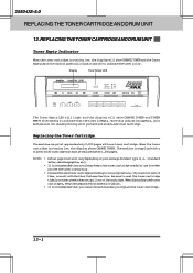
...the toner cartridge is running low, the display shows CHANGE TONER. Display Toner Empty LED 3550 Set Function Clear Tel-index Fine Fax Photo TAD S.Fine F/ T Resolution Mode Super...light and the display will vary depending on and off to indicate the toner is supplied with a starter toner cartridge that you always keep them , consult with one ...toner cartridge. Replacing the Toner Cartridge The machine can print approximately 2,200 pages with Brother Customer Service. Once this indication appears, your average document type (i.e.: standard letter, detailed graphics,...
...the toner cartridge is running low, the display shows CHANGE TONER. Display Toner Empty LED 3550 Set Function Clear Tel-index Fine Fax Photo TAD S.Fine F/ T Resolution Mode Super...light and the display will vary depending on and off to indicate the toner is supplied with a starter toner cartridge that you always keep them , consult with one ...toner cartridge. Replacing the Toner Cartridge The machine can print approximately 2,200 pages with Brother Customer Service. Once this indication appears, your average document type (i.e.: standard letter, detailed graphics,...

Service Manual
Page 7
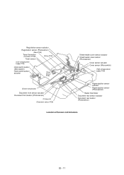
... Top cover Control panel ASSY Drum unit with toner cartridge loaded Laser unit Heat-fixing unit Inner cover Handset Gear drive unit Low-voltage power supply ASSY Bottom plate I - 1 Main cover Scanner frame ASSY NCU PCB ASSY Main PCB Relay PCB High-voltage power...
... Top cover Control panel ASSY Drum unit with toner cartridge loaded Laser unit Heat-fixing unit Inner cover Handset Gear drive unit Low-voltage power supply ASSY Bottom plate I - 1 Main cover Scanner frame ASSY NCU PCB ASSY Main PCB Relay PCB High-voltage power...
Service Manual
Page 19
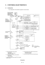
... 1. CONTROL ELECTRONICS III-12 3.1 Configuration III-12 3.2 Main PCB III-13 3.3 Relay PCB III-23 3.4 NCU PCB III-24 3.5 Control Panel PCB III-27 3.6 Power Supply PCBs III-28 [ 1 ] Low-voltage power supply PCB III-28 [ 2 ] High-voltage power supply PCB III-29 OVERVIEW ...III-1 2.
... 1. CONTROL ELECTRONICS III-12 3.1 Configuration III-12 3.2 Main PCB III-13 3.3 Relay PCB III-23 3.4 NCU PCB III-24 3.5 Control Panel PCB III-27 3.6 Power Supply PCBs III-28 [ 1 ] Low-voltage power supply PCB III-28 [ 2 ] High-voltage power supply PCB III-29 OVERVIEW ...III-1 2.
Service Manual
Page 20
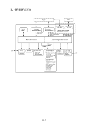
... charger - Developer roller - LED array - Laser unit (including the polygon motor) - Heater roller - Scanner motor Charging, exposing, developing, transferring, erasing, feeding mechanism high-voltage power supplies AC and heat-fixing processes - Laser-sensitive drum - 1. Eraser lamp - OVERVIEW PC/AT MAC Line Control panel RS-232C (Modular connector) [FAX3550/3650/ 8000P/8200P...
... charger - Developer roller - LED array - Laser unit (including the polygon motor) - Heater roller - Scanner motor Charging, exposing, developing, transferring, erasing, feeding mechanism high-voltage power supplies AC and heat-fixing processes - Laser-sensitive drum - 1. Eraser lamp - OVERVIEW PC/AT MAC Line Control panel RS-232C (Modular connector) [FAX3550/3650/ 8000P/8200P...

Service Manual
Page 25
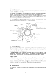
... to paper. 4 Erases the residual potential. Time III - 6 2.2.2 Print process mechanism Toner augers Toner cartridge Toner sensor Paper Developer roller Transfer roller Drum unit Toner supply roller Polygon mirror Polygon motor Laser unit Cover glass Mirror Laser-sensitive drum Cleaner roller Charger (Corona wire) Mirror Electrical charge on the surface of...
... to paper. 4 Erases the residual potential. Time III - 6 2.2.2 Print process mechanism Toner augers Toner cartridge Toner sensor Paper Developer roller Transfer roller Drum unit Toner supply roller Polygon mirror Polygon motor Laser unit Cover glass Mirror Laser-sensitive drum Cleaner roller Charger (Corona wire) Mirror Electrical charge on the surface of...

Service Manual
Page 26
(1) Charging process The high-voltage power supply applies DC bias to the corona wire to the frame. The ion uniformly charges the surface of the laser-sensitive drum to approx. 1000V which ...
(1) Charging process The high-voltage power supply applies DC bias to the corona wire to the frame. The ion uniformly charges the surface of the laser-sensitive drum to approx. 1000V which ...
Service Manual
Page 27
...to be transferred onto the paper according to the same principle as for repulsing toner from the transfer roller) Toner Eraser lamp Toner supply roller DC bias Laser-sensitive drum Developer roller Cleaner roller (4) Transferring process When a paper passes between the developer roller and drum,...eraser lamp emits light to the contact section with the laser-sensitive drum. The toner returns from the toner cartridge by the toner supply roller, and then conveys them to expose the drum surface, which erases the residual electrical charge. (3) Developing process The developing ...
...to be transferred onto the paper according to the same principle as for repulsing toner from the transfer roller) Toner Eraser lamp Toner supply roller DC bias Laser-sensitive drum Developer roller Cleaner roller (4) Transferring process When a paper passes between the developer roller and drum,...eraser lamp emits light to the contact section with the laser-sensitive drum. The toner returns from the toner cartridge by the toner supply roller, and then conveys them to expose the drum surface, which erases the residual electrical charge. (3) Developing process The developing ...
Service Manual
Page 29
... (PC2) Photosensor (PC1) Photosensor (PC1) Photosensor (PC2) Photosensor (PH1) P1 __ Located on Hook switch PCB Relay PCB Relay PCB Relay PCB High-voltage power supply PCB Document sensor PCB Document sensor PCB Toner sensor PCB (on the laser unit) Toner sensor PCB (on the laser unit) Fixing unit • Hook...
... (PC2) Photosensor (PC1) Photosensor (PC1) Photosensor (PC2) Photosensor (PH1) P1 __ Located on Hook switch PCB Relay PCB Relay PCB Relay PCB High-voltage power supply PCB Document sensor PCB Document sensor PCB Toner sensor PCB (on the laser unit) Toner sensor PCB (on the laser unit) Fixing unit • Hook...
Service Manual
Page 30
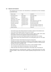
...Registration sensor (Photosensor) (Main PCB) Toner thermister (On back of PCB) (Relay PCB) Toner sensor (Low-voltage power supply PCB) Hook switch sensor (Microswitch) Hook switch sensor actuator (Toner sensor PCB) (Eraser lamp board) Document front sensor actuator ... PCB) Sheet feeder cover sensor actuator Sheet feeder cover sensor (Photosensor) Cover sensor actuator Cover sensor (Microswitch) (High-voltage power supply PCB) Paper ejection sensor actuator Paper ejection sensor (Photosensor) Heater thermister Document rear sensor actuator Document rear sensor (Photosensor) Location of...
...Registration sensor (Photosensor) (Main PCB) Toner thermister (On back of PCB) (Relay PCB) Toner sensor (Low-voltage power supply PCB) Hook switch sensor (Microswitch) Hook switch sensor actuator (Toner sensor PCB) (Eraser lamp board) Document front sensor actuator ... PCB) Sheet feeder cover sensor actuator Sheet feeder cover sensor (Photosensor) Cover sensor actuator Cover sensor (Microswitch) (High-voltage power supply PCB) Paper ejection sensor actuator Paper ejection sensor (Photosensor) Heater thermister Document rear sensor actuator Document rear sensor (Photosensor) Location of...
Service Manual
Page 31
...• Registration sensor *2 On the toner sensor PCB are these sensors: • Toner sensor • Toner thermister *3 On the high-voltage power supply PCB is the paper ejection sensor. *4 On the document sensor PCB are these sensors: • Document front sensor • Document rear sensor *5 ...MODEM 4-pin P9 2-pin P8 Laser unit Laser diode Polygon motor LASER PRINTING UNIT Toner sensor PCB *2 High-voltage *3 3-pin Fan 1 power supply PCB 4-pin Eraser lamp board Fan 2 Main motor Solenoid Heater thermister Fixing Unit Heater (FU lamp) Extended RAM connector P2 40-pin 5-pin...
...• Registration sensor *2 On the toner sensor PCB are these sensors: • Toner sensor • Toner thermister *3 On the high-voltage power supply PCB is the paper ejection sensor. *4 On the document sensor PCB are these sensors: • Document front sensor • Document rear sensor *5 ...MODEM 4-pin P9 2-pin P8 Laser unit Laser diode Polygon motor LASER PRINTING UNIT Toner sensor PCB *2 High-voltage *3 3-pin Fan 1 power supply PCB 4-pin Eraser lamp board Fan 2 Main motor Solenoid Heater thermister Fixing Unit Heater (FU lamp) Extended RAM connector P2 40-pin 5-pin...
Service Manual
Page 32
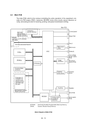
.../3650/8000P/8200P) ROMs ASIC DRAM(s) E2PROM(s) Main PCB Control panel Relay PCB Main motor driver Image processor Fan 2 Main motor Solenoid Low-voltage power supply PCB Document sensor PCB Extended RAM connector Extended I/O connector for scanning, printing, and power transmission shifting.
.../3650/8000P/8200P) ROMs ASIC DRAM(s) E2PROM(s) Main PCB Control panel Relay PCB Main motor driver Image processor Fan 2 Main motor Solenoid Low-voltage power supply PCB Document sensor PCB Extended RAM connector Extended I/O connector for scanning, printing, and power transmission shifting.

Service Manual
Page 38
...1-7 1-8 1-9 1-10 1-11 4 7 6 8 Main PCB Circuit Diagram 5/7 1 Connector for the relay PCB 1-1: Laser drive signals 1-2: High-voltage power supply control signals 1-3: Eraser lamp ON/OFF signal 1-4: Fan 1 control signal 1-5: Signal input from the paper ejection sensor 1-6: Signal input from the registration sensor 1-7:.... (The ASIC controls the HTON signal with the hysteresis characteristics for stabilized heater control.) 3 Connector for the low-voltage power supply 4 Main motor driver which controls recording paper feeding and drum rotation. 5 Fan 2 driver circuit 6 Paper pull-in solenoid ...
...1-7 1-8 1-9 1-10 1-11 4 7 6 8 Main PCB Circuit Diagram 5/7 1 Connector for the relay PCB 1-1: Laser drive signals 1-2: High-voltage power supply control signals 1-3: Eraser lamp ON/OFF signal 1-4: Fan 1 control signal 1-5: Signal input from the paper ejection sensor 1-6: Signal input from the registration sensor 1-7:.... (The ASIC controls the HTON signal with the hysteresis characteristics for stabilized heater control.) 3 Connector for the low-voltage power supply 4 Main motor driver which controls recording paper feeding and drum rotation. 5 Fan 2 driver circuit 6 Paper pull-in solenoid ...
Service Manual
Page 42
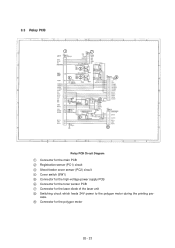
cess. 9 Connector for the laser diode of the laser unit 8 Switching circuit which feeds 24V power to the polygon motor during the printing pro- 3.3 Relay PCB 1 7 2 43 5 6 8 9 Relay PCB Circuit Diagram 1 Connector for the main PCB 2 Registration sensor (PC1) circuit 3 Sheet feeder cover sensor (PC2) circuit 4 Cover switch (SW1) 5 Connector for the high-voltage power supply PCB 6 Connector for the toner sensor PCB 7 Connector for the polygon motor III - 23
cess. 9 Connector for the laser diode of the laser unit 8 Switching circuit which feeds 24V power to the polygon motor during the printing pro- 3.3 Relay PCB 1 7 2 43 5 6 8 9 Relay PCB Circuit Diagram 1 Connector for the main PCB 2 Registration sensor (PC1) circuit 3 Sheet feeder cover sensor (PC2) circuit 4 Cover switch (SW1) 5 Connector for the high-voltage power supply PCB 6 Connector for the toner sensor PCB 7 Connector for the polygon motor III - 23
Service Manual
Page 47
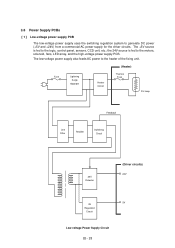
The +5V source is fed to generate DC power (+5V and +24V) from a commercial AC power supply for the driver circuits. The low-voltage power supply also feeds AC power to the logic, control panel, sensors, CCD unit, etc.; the 24V source is fed to the heater ...Line Filter Rectifier Switching Circuit 24V Detector (Driver circuits) 24V 5V 5V Regulation Circuit Low-voltage Power Supply Circuit III - 28 3.6 Power Supply PCBs [ 1 ] Low-voltage power supply PCB The low-voltage power supply uses the switching regulation system to the motors, solenoid, fans, LED array, and the high-voltage...
The +5V source is fed to generate DC power (+5V and +24V) from a commercial AC power supply for the driver circuits. The low-voltage power supply also feeds AC power to the logic, control panel, sensors, CCD unit, etc.; the 24V source is fed to the heater ...Line Filter Rectifier Switching Circuit 24V Detector (Driver circuits) 24V 5V 5V Regulation Circuit Low-voltage Power Supply Circuit III - 28 3.6 Power Supply PCBs [ 1 ] Low-voltage power supply PCB The low-voltage power supply uses the switching regulation system to the motors, solenoid, fans, LED array, and the high-voltage...
Service Manual
Page 48
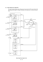
... high-voltage power sources from the 24V source fed from the low-voltage power supply for charging, developing, and transferring in the laser printing process. 24VI Control 1 (TIDN TAIDEN) Fuse Type Resistor R1 11 0.22 1/6w Current Regulator 6 (250µA) ... 8 Voltage Regulator (1.8kV) B52 Q56VR53 Voltage Regulator (1.0kV) 910 Z201 VR201 Voltage Regulator (275V) VR101 Voltage Regulator (700V) VR32 GRID DRMBIAS VCLN High-voltage Power Supply Circuit III - 29
... high-voltage power sources from the 24V source fed from the low-voltage power supply for charging, developing, and transferring in the laser printing process. 24VI Control 1 (TIDN TAIDEN) Fuse Type Resistor R1 11 0.22 1/6w Current Regulator 6 (250µA) ... 8 Voltage Regulator (1.8kV) B52 Q56VR53 Voltage Regulator (1.0kV) 910 Z201 VR201 Voltage Regulator (275V) VR101 Voltage Regulator (700V) VR32 GRID DRMBIAS VCLN High-voltage Power Supply Circuit III - 29

Service Manual
Page 50
... Lamp, and Paper Ejection Sensor Actuator IV-13 1.11 Laser Unit IV-15 1.12 Bottom Plate IV-16 1.13 Low-voltage Power Supply PCB IV-17 1.14 High-voltage Power Supply PCB and Fan 1 IV-18 1.15 Main PCB IV-19 1.16 Relay PCB IV-21 1.17 Shield Bracket and NCU PCB...
... Lamp, and Paper Ejection Sensor Actuator IV-13 1.11 Laser Unit IV-15 1.12 Bottom Plate IV-16 1.13 Low-voltage Power Supply PCB IV-17 1.14 High-voltage Power Supply PCB and Fan 1 IV-18 1.15 Main PCB IV-19 1.16 Relay PCB IV-21 1.17 Shield Bracket and NCU PCB...
Service Manual
Page 51
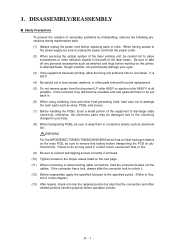
... in your eyes. (3) If the equipment has been printing, allow the fixing unit sufficient time to discharge static electricity; When having access to the power supply, be sure to Sec- otherwise, the electronic parts may result in aluminium foil). IV - 1
... in your eyes. (3) If the equipment has been printing, allow the fixing unit sufficient time to discharge static electricity; When having access to the power supply, be sure to Sec- otherwise, the electronic parts may result in aluminium foil). IV - 1
Service Manual
Page 52
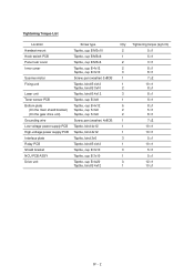
... unit Laser unit Toner sensor PCB Bottom plate (On the main shield bracket) (On the gear drive unit) Grounding wire Low-voltage power supply PCB High-voltage power supply PCB Interface plate Relay PCB Shield bracket NCU PCB ASSY Drive unit Screw type Taptite, cup B M3x10 Taptite, cup B M3x6 Taptite, cup B M3x8...
... unit Laser unit Toner sensor PCB Bottom plate (On the main shield bracket) (On the gear drive unit) Grounding wire Low-voltage power supply PCB High-voltage power supply PCB Interface plate Relay PCB Shield bracket NCU PCB ASSY Drive unit Screw type Taptite, cup B M3x10 Taptite, cup B M3x6 Taptite, cup B M3x8...
Service Manual
Page 54
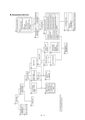
... - s Disassembly Order Flow IV - 4 1 Top cover 2 Handset mount* Side cover** 2 Hook switch PCB* 3 Multi-purpose sheet feeder 11 Laser unit 13 Low-voltage power supply PCB 12 Bottom plate 14 15 High-voltage power supply PCB Main PCB 14 Fan 1 16 Relay PCB 18 Gear drive unit Main motor Solenoids Gears 19 -
... - s Disassembly Order Flow IV - 4 1 Top cover 2 Handset mount* Side cover** 2 Hook switch PCB* 3 Multi-purpose sheet feeder 11 Laser unit 13 Low-voltage power supply PCB 12 Bottom plate 14 15 High-voltage power supply PCB Main PCB 14 Fan 1 16 Relay PCB 18 Gear drive unit Main motor Solenoids Gears 19 -

