
Users Manual - English
Page 82
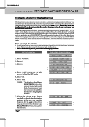
... handset. Press Z (left arrow) or X (right arrow) to malfunction. D/R SET MODE will be on the display screen. This procedure is in two parts: First, you can register the ringing pattern. Have a friend ready to call comes in SET mode; Second, you must wait for someone to call the... 6.TEL OPTIONS 6.DISTINCTIVE DISTINCTIVE:OFF SELECT { } & SET DISTINCTIVE:SET 6.DISTINCTIVE D/R SET MODE PICK UP TO SET START TO SET STOP TO CANCEL 3550-US-5.0 DISTINCTIVE RINGING RECEIVING FAXES AND OTHER CALLS Setting the Distinctive Ringing Function This function is a one you hang up.
... handset. Press Z (left arrow) or X (right arrow) to malfunction. D/R SET MODE will be on the display screen. This procedure is in two parts: First, you can register the ringing pattern. Have a friend ready to call comes in SET mode; Second, you must wait for someone to call the... 6.TEL OPTIONS 6.DISTINCTIVE DISTINCTIVE:OFF SELECT { } & SET DISTINCTIVE:SET 6.DISTINCTIVE D/R SET MODE PICK UP TO SET START TO SET STOP TO CANCEL 3550-US-5.0 DISTINCTIVE RINGING RECEIVING FAXES AND OTHER CALLS Setting the Distinctive Ringing Function This function is a one you hang up.
Users Manual - English
Page 109
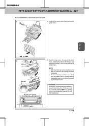
HOT ! 12-2 3550-US-5.0 REPLACING THE TONER CARTRIDGE AND DRUM UNIT Follow these steps to avoid spilling and scattering the toner. WARNING Just after you have used the machine, some internal parts of the machine 2) Open the top cover. Ch.12 : ON : OFF 2) Top cover Drum unit Inside of the machine will be extremely... large piece of disposable paper to replace the toner cartridge: 1) 1) Turn off the power switch and unplug the power cord. So, never touch the shaded parts shown in the left illustration.
HOT ! 12-2 3550-US-5.0 REPLACING THE TONER CARTRIDGE AND DRUM UNIT Follow these steps to avoid spilling and scattering the toner. WARNING Just after you have used the machine, some internal parts of the machine 2) Open the top cover. Ch.12 : ON : OFF 2) Top cover Drum unit Inside of the machine will be extremely... large piece of disposable paper to replace the toner cartridge: 1) 1) Turn off the power switch and unplug the power cord. So, never touch the shaded parts shown in the left illustration.
Users Manual - English
Page 112
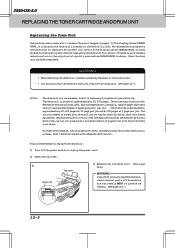
... drum unit should be replaced. The actual number of pages that you use only genuine toner, and the product should be used the machine, some internal parts of the machine are many factors that determine the actual drum life, we can not guarantee a minimum number of pages your drum.... 3550-US-5.0 REPLACING THE TONER CARTRIDGE AND DRUM UNIT Replacing the Drum Unit The machine uses a drum unit to replace the drum unit: 1) Turn off the ...
... drum unit should be replaced. The actual number of pages that you use only genuine toner, and the product should be used the machine, some internal parts of the machine are many factors that determine the actual drum life, we can not guarantee a minimum number of pages your drum.... 3550-US-5.0 REPLACING THE TONER CARTRIDGE AND DRUM UNIT Replacing the Drum Unit The machine uses a drum unit to replace the drum unit: 1) Turn off the ...

Users Manual - English
Page 116
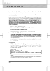
... extremelyHOT! Inside the machine WARNING Just after you have used the fax machine, some internal parts of the machine, never touch the shaded parts shown in the diagram to avoid spilling and scattering the toner. 1. 3550-US-5.0 REGULAR MAINTENANCE AND TROUBLESHOOTING WARNING • Donotuseisopropylalcoholtocleanthescannerwindoworthetonersensor. • Donottouchthescannerwindowwithyourfinger. • Handle the drum unit carefully because it...
... extremelyHOT! Inside the machine WARNING Just after you have used the fax machine, some internal parts of the machine, never touch the shaded parts shown in the diagram to avoid spilling and scattering the toner. 1. 3550-US-5.0 REGULAR MAINTENANCE AND TROUBLESHOOTING WARNING • Donotuseisopropylalcoholtocleanthescannerwindoworthetonersensor. • Donottouchthescannerwindowwithyourfinger. • Handle the drum unit carefully because it...

Users Manual - English
Page 131
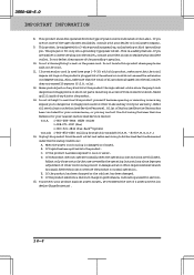
... or premises wiring using a compatible modular jack which is provided with Part 68 of your equipment. The REN is useful to determine the quantity of devices you will be connected to your IntelliFAX3550, contact Brother service personnel at 1-800-284-4FAX(Voice)(U.S.A.Only). 1-908-271-1937...This equipment is hearing aid compatible. You will be notified in the off-peak hours, such as possible. Only) Ch.14 14-1 3550-US-5.0 IMPORTANT INFORMATION 14. When programming emergency numbers and/or making test calls to emergency numbers: • Remain on obtaining service ...
... or premises wiring using a compatible modular jack which is provided with Part 68 of your equipment. The REN is useful to determine the quantity of devices you will be connected to your IntelliFAX3550, contact Brother service personnel at 1-800-284-4FAX(Voice)(U.S.A.Only). 1-908-271-1937...This equipment is hearing aid compatible. You will be notified in the off-peak hours, such as possible. Only) Ch.14 14-1 3550-US-5.0 IMPORTANT INFORMATION 14. When programming emergency numbers and/or making test calls to emergency numbers: • Remain on obtaining service ...
Users Manual - English
Page 132
...Rules. This means that interference will not occur in a particular installation. MANUFACTURED : BROTHER INDUSTRIES, LTD. 15-1 Naeshiro-cho Mizuho-ku Nagoya, 467 Japan This product ...the user is mandatory for help. If this manual may not be attached to Part 15 of the following measures: • Reorientorrelocatethereceivingantenna. • Increase the separation ...CFR Subchapter J. However, there is certified as a Class I laser product under the U.S. 3550-US-5.0 IMPORTANT INFORMATION Warning For protection against harmful interference in a residential installation. Caution Use ...
...Rules. This means that interference will not occur in a particular installation. MANUFACTURED : BROTHER INDUSTRIES, LTD. 15-1 Naeshiro-cho Mizuho-ku Nagoya, 467 Japan This product ...the user is mandatory for help. If this manual may not be attached to Part 15 of the following measures: • Reorientorrelocatethereceivingantenna. • Increase the separation ...CFR Subchapter J. However, there is certified as a Class I laser product under the U.S. 3550-US-5.0 IMPORTANT INFORMATION Warning For protection against harmful interference in a residential installation. Caution Use ...
Users Manual - English
Page 134
... the use of any kind into this product, make sure that the total of other risks and may touch dangerous voltage points or short out parts resulting in damage and will fit only into the extension cord do not exceed the extension cord ampere rating. This product should be operated from... Service Numbers for your electrician to normal operation. A list of Authorized Service Centers has been included for your convenience, or you to rain or water. 3550-US-5.0 IMPORTANT INFORMATION 8. Thisproductisequippedwitha3-wiregroundingtypeplug,aplughavingathird(grounding) pin.
... the use of any kind into this product, make sure that the total of other risks and may touch dangerous voltage points or short out parts resulting in damage and will fit only into the extension cord do not exceed the extension cord ampere rating. This product should be operated from... Service Numbers for your electrician to normal operation. A list of Authorized Service Centers has been included for your convenience, or you to rain or water. 3550-US-5.0 IMPORTANT INFORMATION 8. Thisproductisequippedwitha3-wiregroundingtypeplug,aplughavingathird(grounding) pin.

Service Manual
Page 2
© Copyright Brother 1998 All rights reserved. Specifications are subject to change without permission in any form or by any means without notice. No part of this publication may be reproduced in writing from the publisher.
© Copyright Brother 1998 All rights reserved. Specifications are subject to change without permission in any form or by any means without notice. No part of this publication may be reproduced in writing from the publisher.
Service Manual
Page 3
.... CHAPTER IV. CHAPTER V. The specifications and functions are subject to rapidly repair the equipment and order any necessary spare parts. CHAPTER VI. CHAPTER II. PREFACE This publication is made up of the Brother facsimile equipment. To perform appropriate maintenance so that service personnel will be destined for field troubleshooting and repair-disassembly...
.... CHAPTER IV. CHAPTER V. The specifications and functions are subject to rapidly repair the equipment and order any necessary spare parts. CHAPTER VI. CHAPTER II. PREFACE This publication is made up of the Brother facsimile equipment. To perform appropriate maintenance so that service personnel will be destined for field troubleshooting and repair-disassembly...
Service Manual
Page 22
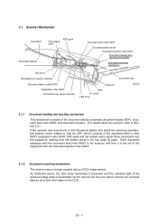
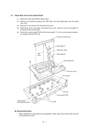
2.1 Scanner Mechanism Document ADF parts Nip-related parts Document stacker Document feed roller ASSY Document pressure bar Document ejection roller ASSY Document feeding and ejecting mechanism Document scanning mechanism 2nd mirror Document front ... the scanning operation, the scanner motor rotates so that the ADF (which consists of the document take -in roller ASSY, separation roller ASSY, ADF parts and nip-related parts) feeds those documents into the lens which reduces the scanned data so as to Section 2.3.) If the operator sets documents on the CCD.
2.1 Scanner Mechanism Document ADF parts Nip-related parts Document stacker Document feed roller ASSY Document pressure bar Document ejection roller ASSY Document feeding and ejecting mechanism Document scanning mechanism 2nd mirror Document front ... the scanning operation, the scanner motor rotates so that the ADF (which consists of the document take -in roller ASSY, separation roller ASSY, ADF parts and nip-related parts) feeds those documents into the lens which reduces the scanned data so as to Section 2.3.) If the operator sets documents on the CCD.

Service Manual
Page 45
... and telephone units) is to switch a line to the facsimile unit or to the telephone, which is carried out by selecting the constants of the parts in this circuit so as to conform to the communications regulations or codes of each other in the direct current band.
... and telephone units) is to switch a line to the facsimile unit or to the telephone, which is carried out by selecting the constants of the parts in this circuit so as to conform to the communications regulations or codes of each other in the direct current band.
Service Manual
Page 51
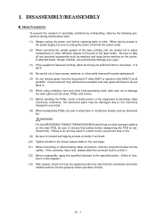
...self-tapping screws correctly, if removed. (10) Tighten screws to discharge static electricity; Failure to remove that the connectors and other parts removed for parts replacement. (5) Do not remove gears from the power outlet. (2) When servicing the optical system of the equipment to the torque ...values listed on the printer. otherwise, the electronic parts may result in aluminium foil). 1. If the connector has a lock, always slide the connector lock to unlock it. (12) Before reassembly...
...self-tapping screws correctly, if removed. (10) Tighten screws to discharge static electricity; Failure to remove that the connectors and other parts removed for parts replacement. (5) Do not remove gears from the power outlet. (2) When servicing the optical system of the equipment to the torque ...values listed on the printer. otherwise, the electronic parts may result in aluminium foil). 1. If the connector has a lock, always slide the connector lock to unlock it. (12) Before reassembly...
Service Manual
Page 53
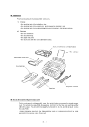
... s How to Access the Object Component • On the next page is a disassembly order flow which helps you access the object component. You should remove parts numbered 1, 3, B, and E so as to the disassembly procedure, (1) Unplug - s Preparation Prior to proceeding to access the relay PCB. • Unless otherwise specified, the disassembled...
... s How to Access the Object Component • On the next page is a disassembly order flow which helps you access the object component. You should remove parts numbered 1, 3, B, and E so as to the disassembly procedure, (1) Unplug - s Preparation Prior to proceeding to access the relay PCB. • Unless otherwise specified, the disassembled...
Service Manual
Page 54
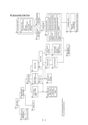
ADF parts - s Disassembly Order Flow IV - 4 1 Top cover 2 Handset mount* Side cover** 2 Hook switch PCB* 3 Multi-purpose sheet feeder 11 Laser unit 13 Low-voltage power supply ... 14 15 High-voltage power supply PCB Main PCB 14 Fan 1 16 Relay PCB 18 Gear drive unit Main motor Solenoids Gears 19 - Nip-related parts Control panel - FPC key 6 Document feed roller ASSY 6 Document ejection roller ASSY 7 Inner cover 8 Scanner frame ASSY Mirrors Ejection leaf spring Scanner motor Pressure roller...
ADF parts - s Disassembly Order Flow IV - 4 1 Top cover 2 Handset mount* Side cover** 2 Hook switch PCB* 3 Multi-purpose sheet feeder 11 Laser unit 13 Low-voltage power supply ... 14 15 High-voltage power supply PCB Main PCB 14 Fan 1 16 Relay PCB 18 Gear drive unit Main motor Solenoids Gears 19 - Nip-related parts Control panel - FPC key 6 Document feed roller ASSY 6 Document ejection roller ASSY 7 Inner cover 8 Scanner frame ASSY Mirrors Ejection leaf spring Scanner motor Pressure roller...
Service Manual
Page 57
... pawls s Reassembling Notes • When installing the spring plate B and separation rubber, align their cutouts with the FPC key. Document pressure bar ADF parts Spring plate A Separation rubber Spring plate B Nip-related parts Panel rear cover 15 "X" pawls Control panel (placed upside down . (2) Remove the document pressure bar, ADF... parts, and nip-related parts from the panel rear cover. (3) Remove the two screws from the panel rear cover. (4) While lifting up the front edge of the...
... pawls s Reassembling Notes • When installing the spring plate B and separation rubber, align their cutouts with the FPC key. Document pressure bar ADF parts Spring plate A Separation rubber Spring plate B Nip-related parts Panel rear cover 15 "X" pawls Control panel (placed upside down . (2) Remove the document pressure bar, ADF... parts, and nip-related parts from the panel rear cover. (3) Remove the two screws from the panel rear cover. (4) While lifting up the front edge of the...

Service Manual
Page 60
... the PCB. Disconnect the CCD harness and LED array harness from the main cover: • Cover glass. 1.8 Scanner Frame ASSY (1) You can remove the following parts from the top of the scanner frame ASSY without taking out the ASSY from the document sensor PCB.
... the PCB. Disconnect the CCD harness and LED array harness from the main cover: • Cover glass. 1.8 Scanner Frame ASSY (1) You can remove the following parts from the top of the scanner frame ASSY without taking out the ASSY from the document sensor PCB.

Service Manual
Page 67
... heater harness (of the PCBs. IV - 17 NCU PCB (beneath the main PCB) Main cover (placed upside down ) s Reassembling Notes • When reassembling the above parts, make sure that the above harnesses are routed through the clamps provided on the main cover as illustrated in Section 1.23. Low-voltage power supply...
... heater harness (of the PCBs. IV - 17 NCU PCB (beneath the main PCB) Main cover (placed upside down ) s Reassembling Notes • When reassembling the above parts, make sure that the above harnesses are routed through the clamps provided on the main cover as illustrated in Section 1.23. Low-voltage power supply...

Service Manual
Page 68
... power supply PCB, check the high-voltage contacts for any toner particles, paper dust or dirt, and clean them out. • When reassembling the above parts, make sure that the harnesses are recommended to the front of the machine. (3) Slightly lift up (when the equipment is removed, you are routed on...
... power supply PCB, check the high-voltage contacts for any toner particles, paper dust or dirt, and clean them out. • When reassembling the above parts, make sure that the harnesses are recommended to the front of the machine. (3) Slightly lift up (when the equipment is removed, you are routed on...

Service Manual
Page 74
... gear system Paper feed solenoid s Reassembling Notes • If the paper feed solenoid, solenoid lever, or clutch release lever has been removed, assemble the removed parts as shown above. (4) To replace the paper feed solenoid, solenoid lever or clutch release lever, remove the three screws and take off the motor bracket...
... gear system Paper feed solenoid s Reassembling Notes • If the paper feed solenoid, solenoid lever, or clutch release lever has been removed, assemble the removed parts as shown above. (4) To replace the paper feed solenoid, solenoid lever or clutch release lever, remove the three screws and take off the motor bracket...
Service Manual
Page 148
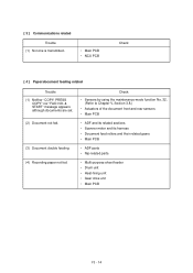
...; ADF and its related sections • Scanner motor and its harness • Document feed rollers and their related gears • Main PCB • ADF parts • Nip-related parts • Multi-purpose sheet feeder • Drum unit • Heat-fixing unit • Gear drive unit • Main PCB VI - 14 [ 3 ] Communications related...
...; ADF and its related sections • Scanner motor and its harness • Document feed rollers and their related gears • Main PCB • ADF parts • Nip-related parts • Multi-purpose sheet feeder • Drum unit • Heat-fixing unit • Gear drive unit • Main PCB VI - 14 [ 3 ] Communications related...

