The Bose® Lifestyle® amplifier - Owner's guide
Page 4
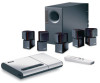
If an external antenna or cable system is practical. ©2001 Bose Corporation, The Mountain, Framingham, MA 01701-9168 USA 255805 AM Rev.00 JN10494 2b January 10, 2002 AM262840_00_V.pdf In particular, it specifies that the cable ground shall be connected to the grounding system of the building, as... on a different circuit than the one or more of the FCC rules. This equipment generates, uses, and can be sure the antenna or cable system is provided to call the CATV system installer's attention to Article 820-40 of the NEC (of the receiver or radio remote control could...
If an external antenna or cable system is practical. ©2001 Bose Corporation, The Mountain, Framingham, MA 01701-9168 USA 255805 AM Rev.00 JN10494 2b January 10, 2002 AM262840_00_V.pdf In particular, it specifies that the cable ground shall be connected to the grounding system of the building, as... on a different circuit than the one or more of the FCC rules. This equipment generates, uses, and can be sure the antenna or cable system is provided to call the CATV system installer's attention to Article 820-40 of the NEC (of the receiver or radio remote control could...
The Bose® Lifestyle® amplifier - Owner's guide
Page 6
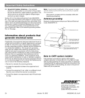
...: Use only the power cord supplied with Bose non-powered environmental speakers or Bose non-powered accessory speakers ONLY. Unpacking the carton WARNING: To avoid danger of suffocation, keep the plastic bags out of the reach of the shipping carton 30-ft audio input cable PN197406 Lifestyle® stereo amplifier Owner's guide...
...: Use only the power cord supplied with Bose non-powered environmental speakers or Bose non-powered accessory speakers ONLY. Unpacking the carton WARNING: To avoid danger of suffocation, keep the plastic bags out of the reach of the shipping carton 30-ft audio input cable PN197406 Lifestyle® stereo amplifier Owner's guide...
The Bose® Lifestyle® amplifier - Owner's guide
Page 7
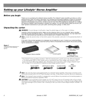
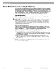
... location for your amplifier: • Locate the amplifier indoors and within the reach of the supplied 30-foot audio input cable. • Place the amplifier in an area where the maximum ambient temperature is less than 104°F (45°C). •...not need to be placed indoors. Setting Up Your Lifestyle® Stereo Amplifier Selecting a location for your Lifestyle® stereo amplifier Select a location for your Lifestyle® stereo amplifier and mount it according to either your Lifestyle® system or the accessory speakers, consider the following...
... location for your amplifier: • Locate the amplifier indoors and within the reach of the supplied 30-foot audio input cable. • Place the amplifier in an area where the maximum ambient temperature is less than 104°F (45°C). •...not need to be placed indoors. Setting Up Your Lifestyle® Stereo Amplifier Selecting a location for your Lifestyle® stereo amplifier Select a location for your Lifestyle® stereo amplifier and mount it according to either your Lifestyle® system or the accessory speakers, consider the following...
The Bose® Lifestyle® amplifier - Owner's guide
Page 9
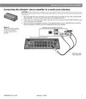
... the red RCA piggyback connector into the R (right) INPUT jack of the supplied cable into the SYSTEM CONTROL jack on the rear of the amplifier. 3. At the other connections. 1. Setting Up Your Lifestyle® Stereo Amplifier Connecting the Lifestyle® stereo amplifier to a multi-room interface CAUTION: Before making...
... the red RCA piggyback connector into the R (right) INPUT jack of the supplied cable into the SYSTEM CONTROL jack on the rear of the amplifier. 3. At the other connections. 1. Setting Up Your Lifestyle® Stereo Amplifier Connecting the Lifestyle® stereo amplifier to a multi-room interface CAUTION: Before making...
The Bose® Lifestyle® amplifier - Owner's guide
Page 11
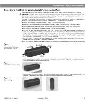
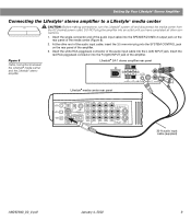
... the 3.5 mm mini-plug into the L (left) INPUT jack. Figure 8 Cable connections between the Lifestyle® media center and the Lifestyle® stereo amplifier Lifestyle® SA-1 stereo amplifier rear panel Lifestyle® media center rear panel 30-ft audio input cable (supplied) AM262840_00_V.pdf January 4, 2002 9 DO NOT plug the amplifier...
... the 3.5 mm mini-plug into the L (left) INPUT jack. Figure 8 Cable connections between the Lifestyle® media center and the Lifestyle® stereo amplifier Lifestyle® SA-1 stereo amplifier rear panel Lifestyle® media center rear panel 30-ft audio input cable (supplied) AM262840_00_V.pdf January 4, 2002 9 DO NOT plug the amplifier...
The Bose® Lifestyle® amplifier - Owner's guide
Page 13
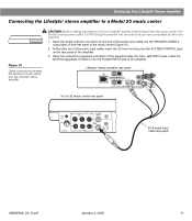
...; stereo amplifier to a Model 20 music center ® Figure 10 Cable connections between the Model 20 music center and the Lifestyle® stereo amplifier CAUTION: Before making connections, turn the Lifestyle® system off and disconnect the music center from the AC (mains) power outlet.... Insert the white RCA piggyback connector of the amplifier. Lifestyle® stereo amplifier rear panel 4 Ω MINIMUM LL R L SYSTEM RR CONTROL L R +- DO NOT plug the amplifier ...
...; stereo amplifier to a Model 20 music center ® Figure 10 Cable connections between the Model 20 music center and the Lifestyle® stereo amplifier CAUTION: Before making connections, turn the Lifestyle® system off and disconnect the music center from the AC (mains) power outlet.... Insert the white RCA piggyback connector of the amplifier. Lifestyle® stereo amplifier rear panel 4 Ω MINIMUM LL R L SYSTEM RR CONTROL L R +- DO NOT plug the amplifier ...
The Bose® Lifestyle® amplifier - Owner's guide
Page 15
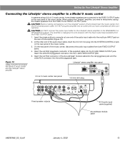
... unplug the theater speakers from the FIXED OUTPUT jacks. 1. At the other connections. CAUTION: DO NOT connect the audio input cable for the Lifestyle® stereo amplifier to the FIXED OUTPUT jacks on the rear panel of the Acoustimass® module... RCA piggyback connector of the music center, disconnect the audio input cables from the AC (mains) power outlet. Figure 12 Cable connections between the Model 5 music center and the Lifestyle® stereo amplifier Model 5 music center rear panel Lifestyle® stereo amplifier rear panel 4 Ω MINIMUM ...
... unplug the theater speakers from the FIXED OUTPUT jacks. 1. At the other connections. CAUTION: DO NOT connect the audio input cable for the Lifestyle® stereo amplifier to the FIXED OUTPUT jacks on the rear panel of the Acoustimass® module... RCA piggyback connector of the music center, disconnect the audio input cables from the AC (mains) power outlet. Figure 12 Cable connections between the Model 5 music center and the Lifestyle® stereo amplifier Model 5 music center rear panel Lifestyle® stereo amplifier rear panel 4 Ω MINIMUM ...
The Bose® Lifestyle® amplifier - Owner's guide
Page 16
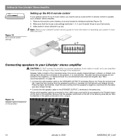
...sure that the house code settings (switches 1, 2, 3, and 4) match those in your Lifestyle® system owner's guide for more than one room. Figure 14 Speaker cable connections on ). Setting Up Your Lifestyle® Stereo Amplifier ® Figure 13 RC-5 remote switch settings Setting up the RC... the speaker's positive (+) terminal into the black jack and release the tab. • Connect the left speaker cable to the R (right) output on operating your Lifestyle® stereo amplifier. 1. Notice which is usually marked (striped, collared, or ribbed), indicating that the...
...sure that the house code settings (switches 1, 2, 3, and 4) match those in your Lifestyle® system owner's guide for more than one room. Figure 14 Speaker cable connections on ). Setting Up Your Lifestyle® Stereo Amplifier ® Figure 13 RC-5 remote switch settings Setting up the RC... the speaker's positive (+) terminal into the black jack and release the tab. • Connect the left speaker cable to the R (right) output on operating your Lifestyle® stereo amplifier. 1. Notice which is usually marked (striped, collared, or ribbed), indicating that the...

The Bose® Lifestyle® amplifier - Owner's guide
Page 18
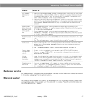
... annually, and re-apply as RTV adhesive, to arrange for home theater (Lifestyle® 12 or Lifestyle® 8 systems), make sure the audio input cable is plugged into the FIXED OUTPUTs on . • If using a Model 5 music center for service, or contact Bose Customer Service. Refer to spill into SPEAKER ZONE 2. • If using a Model...
... annually, and re-apply as RTV adhesive, to arrange for home theater (Lifestyle® 12 or Lifestyle® 8 systems), make sure the audio input cable is plugged into the FIXED OUTPUTs on . • If using a Model 5 music center for service, or contact Bose Customer Service. Refer to spill into SPEAKER ZONE 2. • If using a Model...
The Bose® Lifestyle® amplifier - Owner's guide
Page 19
...feature. Make sure the wires are provided on the warranty card that end of the coverage are connected + to "Legacy". Details of the cable to Bose. AM262840_00_V.pdf January 4, 2002 17 If the speaker still does not play , the problem is in the SYSTEM CONTROL 2 jack. &#...firmly inserted in the speaker. Zone 2 does not • If you are correct. tion, consult your Lifestyle® DVD system's owners guide. Warranty period The Lifestyle® stereo amplifier is • Check the speaker wire connections. Interference • Make sure the speaker...
...feature. Make sure the wires are provided on the warranty card that end of the coverage are connected + to "Legacy". Details of the cable to Bose. AM262840_00_V.pdf January 4, 2002 17 If the speaker still does not play , the problem is in the SYSTEM CONTROL 2 jack. &#...firmly inserted in the speaker. Zone 2 does not • If you are correct. tion, consult your Lifestyle® DVD system's owners guide. Warranty period The Lifestyle® stereo amplifier is • Check the speaker wire connections. Interference • Make sure the speaker...

Owner's guide
Page 4
... described in the operating instructions or as contact with respect to proper grounding of the mast and supporting structure, grounding of cable entry as per National Electrical Code, ANSI/NFPA 70. b December 20, 2001 AM191409_01_V.pdf English Important Safety Instructions 18.... Use proper power sources - If an external antenna or cable system is practical. Section 810 of antenna-discharge unit, connection to the antenna grounding illustration on the product. 19. Plug...
... described in the operating instructions or as contact with respect to proper grounding of the mast and supporting structure, grounding of cable entry as per National Electrical Code, ANSI/NFPA 70. b December 20, 2001 AM191409_01_V.pdf English Important Safety Instructions 18.... Use proper power sources - If an external antenna or cable system is practical. Section 810 of antenna-discharge unit, connection to the antenna grounding illustration on the product. 19. Plug...
Owner's guide
Page 7
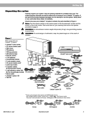
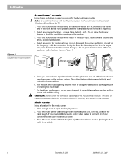
... system. WARNING: he Acoustimass module weighs 33 pounds (15 kg). Remote control Rubber feet Stereo cable Lifestyle® system CD Test CD * Power cord and pack shown above are shown below. Notify Bose® or your Lifestyle® 12 system: • Lifestyle® music center • AC power (mains) pack* • Wire cover • FM antenna...
... system. WARNING: he Acoustimass module weighs 33 pounds (15 kg). Remote control Rubber feet Stereo cable Lifestyle® system CD Test CD * Power cord and pack shown above are shown below. Notify Bose® or your Lifestyle® 12 system: • Lifestyle® music center • AC power (mains) pack* • Wire cover • FM antenna...
Owner's guide
Page 8
Vibration can cause the speakers to 20 feet (6.1 m) distance from your Lifestyle® 12 system (Figures 2 and 3). You may wish to vary this distance based on room conditions and personal preference. 3. The front speaker cables allow up to the TV without affecting picture quality. 6 December 20, 2001 ... You may obtain rubber feet (part no. 178321), free of the picture, so that the sound does not become too separated from Bose®. For additional stability, you can place them up to move, particularly on smooth surfaces like marble, glass, or highly polished wood....
Vibration can cause the speakers to 20 feet (6.1 m) distance from your Lifestyle® 12 system (Figures 2 and 3). You may wish to vary this distance based on room conditions and personal preference. 3. The front speaker cables allow up to the TV without affecting picture quality. 6 December 20, 2001 ... You may obtain rubber feet (part no. 178321), free of the picture, so that the sound does not become too separated from Bose®. For additional stability, you can place them up to move, particularly on smooth surfaces like marble, glass, or highly polished wood....

Owner's guide
Page 9
... the speakers at the listener. Place the speaker on line with books. Placing speakers in the back half of your room. The surround cables allow up to reflect sound off one at the front edge of the shelf. Do not direct the sound straight at ear height or ...feet (15.2 m) distance from the Acoustimass module. Note: If you do not pinpoint the exact location of the sound source (Figure 3). The center speaker cable allows up to create a wider area of direct sound (Figure 3). AM191409_01_V.pdf December 20, 2001 7 Setting Up Figure 2 Recommended front speaker locations Center...
... the speakers at the listener. Place the speaker on line with books. Placing speakers in the back half of your room. The surround cables allow up to reflect sound off one at the front edge of the shelf. Do not direct the sound straight at ear height or ...feet (15.2 m) distance from the Acoustimass module. Note: If you do not pinpoint the exact location of the sound source (Figure 3). The center speaker cable allows up to create a wider area of direct sound (Figure 3). AM191409_01_V.pdf December 20, 2001 7 Setting Up Figure 2 Recommended front speaker locations Center...
Owner's guide
Page 10
...of the bottom surface. Select a convenient location - Do not allow for cable length. Place the Acoustimass module within 30 feet (9.1 m) of the Acoustimass ... furniture or drapes to block the ventilation openings of the audio input cable, speaker cables, and an AC power (mains) outlet. 4. For proper ventilation,...in Figure 3). 2. Once you need additional audio and/or video cables to the same end of your components, see the example along the... CAUTION: Do not cover the ventilation openings of the audio input cable). 8 December 20, 2001 AM191409_01_V.pdf The rubber feet provide increased...
...of the bottom surface. Select a convenient location - Do not allow for cable length. Place the Acoustimass module within 30 feet (9.1 m) of the Acoustimass ... furniture or drapes to block the ventilation openings of the audio input cable, speaker cables, and an AC power (mains) outlet. 4. For proper ventilation,...in Figure 3). 2. Once you need additional audio and/or video cables to the same end of your components, see the example along the... CAUTION: Do not cover the ventilation openings of the audio input cable). 8 December 20, 2001 AM191409_01_V.pdf The rubber feet provide increased...
Owner's guide
Page 11
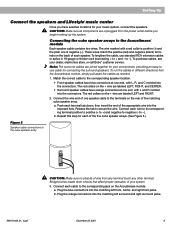
...each terminal tab down, then insert the end of your dealer, electronics store, or call Bose® customer service. to the corresponding jack on the rear of one end, with L ...positive to positive (+ to +) and negative to + and - To lengthen the cable, use standard RCA extension cables or splice in different directions from the power outlet before you have selected locations for ...connectors into the connectors. AM191409_01_V.pdf December 20, 2001 9 Setting Up Connect the speakers and Lifestyle® music center Once you begin hooking up the system. These wires match the positive ...
...each terminal tab down, then insert the end of your dealer, electronics store, or call Bose® customer service. to the corresponding jack on the rear of one end, with L ...positive to positive (+ to +) and negative to + and - To lengthen the cable, use standard RCA extension cables or splice in different directions from the power outlet before you have selected locations for ...connectors into the connectors. AM191409_01_V.pdf December 20, 2001 9 Setting Up Connect the speakers and Lifestyle® music center Once you begin hooking up the system. These wires match the positive ...
Owner's guide
Page 12
... 6). If the black connector is not inserted fully into SYSTEM CONTROL 1 ® LIFESTYLE ® MODEL 5 MUSIC CENTER B Z G642 950 D S T BOSE Corporation UL LISTED 917D AUDIO ® EQUIPMENT MANUFACTURED: TÜV Rheinland BOSE CORPORATION, FRAMINGHAM, MA 01701-9168 MADE IN USA geprüdfte Sicherheit SPEAKERS L FIXED... 20, 2001 AM191409_01_V.pdf Insert the three connectors at the angle shown in your Lifestyle® 12 system are fully inserted into each of the audio input cable into the L (left) FIXED OUTPUT jack Note: Be sure the connectors are designed...
... 6). If the black connector is not inserted fully into SYSTEM CONTROL 1 ® LIFESTYLE ® MODEL 5 MUSIC CENTER B Z G642 950 D S T BOSE Corporation UL LISTED 917D AUDIO ® EQUIPMENT MANUFACTURED: TÜV Rheinland BOSE CORPORATION, FRAMINGHAM, MA 01701-9168 MADE IN USA geprüdfte Sicherheit SPEAKERS L FIXED... 20, 2001 AM191409_01_V.pdf Insert the three connectors at the angle shown in your Lifestyle® 12 system are fully inserted into each of the audio input cable into the L (left) FIXED OUTPUT jack Note: Be sure the connectors are designed...
Owner's guide
Page 13
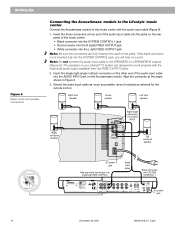
... in UK or Singapore • Model PS72, 230V in Europe • Model PS77, 240V in Australia 1. Connecting the music center AC (mains) power pack The Lifestyle® music center comes with a 120V AC (mains) power pack for use in doubt, contact your area. Note: Do not plug the AC power pack... the AC power cord into the Acoustimass module AC power jack. Firmly insert the small connector on the end of the AC (mains) power pack cable into the AC POWER jack on the back of the power (mains) cord into a power outlet until all component connections are complete. In Europe, use...
... in UK or Singapore • Model PS72, 230V in Europe • Model PS77, 240V in Australia 1. Connecting the music center AC (mains) power pack The Lifestyle® music center comes with a 120V AC (mains) power pack for use in doubt, contact your area. Note: Do not plug the AC power pack... the AC power cord into the Acoustimass module AC power jack. Firmly insert the small connector on the end of the AC (mains) power pack cable into the AC POWER jack on the back of the power (mains) cord into a power outlet until all component connections are complete. In Europe, use...
Owner's guide
Page 14
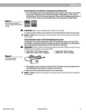
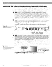
... center to the music center inputs. Laserdisc Cable TV LRV L R V VCR TV L R Lifestyle® music center ® LIFESTYLE ® MODEL 5 MUSIC CENTER B Z T G642 950 D S BOSE Corporation UL LISTED 917D AUDIO ® EQUIPMENT MANUFACTURED: TÜV Rheinland BOSE CORPORATION, FRAMINGHAM, MA 01701-9168 MADE IN...players are available at many electronics stores, or call Bose®. Most audio cables are three basic methods for setting up the primary video sound source The Lifestyle® 12 system has one 6-foot (1.8 m) stereo cable to connect the right (R) and left (L) jacks....
... center to the music center inputs. Laserdisc Cable TV LRV L R V VCR TV L R Lifestyle® music center ® LIFESTYLE ® MODEL 5 MUSIC CENTER B Z T G642 950 D S BOSE Corporation UL LISTED 917D AUDIO ® EQUIPMENT MANUFACTURED: TÜV Rheinland BOSE CORPORATION, FRAMINGHAM, MA 01701-9168 MADE IN...players are available at many electronics stores, or call Bose®. Most audio cables are three basic methods for setting up the primary video sound source The Lifestyle® 12 system has one 6-foot (1.8 m) stereo cable to connect the right (R) and left (L) jacks....
Owner's guide
Page 15
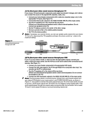
...• Set TV to the stereo position. Note: To ensure proper stereo or surround sound, connect the L and R audio outputs from a cable TV box), in some cases the stereo or surround encoding may be sure to use the L and R audio outputs from your music center ... the VIDEO SOUND INPUTs of the music center. Laserdisc Cable TV LRV VCR L R V Lifestyle® music center ® LIFESTYLE ® MODEL 5 MUSIC CENTER B Z T G642 950 D S BOSE Corporation UL LISTED 917D AUDIO ® EQUIPMENT MANUFACTURED: TÜV Rheinland BOSE CORPORATION, FRAMINGHAM, MA 01701-9168 MADE IN USA gepr...
...• Set TV to the stereo position. Note: To ensure proper stereo or surround sound, connect the L and R audio outputs from a cable TV box), in some cases the stereo or surround encoding may be sure to use the L and R audio outputs from your music center ... the VIDEO SOUND INPUTs of the music center. Laserdisc Cable TV LRV VCR L R V Lifestyle® music center ® LIFESTYLE ® MODEL 5 MUSIC CENTER B Z T G642 950 D S BOSE Corporation UL LISTED 917D AUDIO ® EQUIPMENT MANUFACTURED: TÜV Rheinland BOSE CORPORATION, FRAMINGHAM, MA 01701-9168 MADE IN USA gepr...


