The Bose® Lifestyle® amplifier - Owner's guide
Page 4
...Class B digital device, pursuant to radio communications. Important Safety Instructions 20. Ground All Outdoor Antennas - If an external antenna or cable system is no guarantee that generate electrical noise If applicable, this equipment does cause harmful interference to grounding electrodes, and requirements for ...comply with the instructions, may cause harmful interference to Part 15 of USA) that the cable ground shall be sure the antenna or cable system is practical. ©2001 Bose Corporation, The Mountain, Framingham, MA 01701-9168 USA 255805 AM Rev.00 JN10494 2b ...
...Class B digital device, pursuant to radio communications. Important Safety Instructions 20. Ground All Outdoor Antennas - If an external antenna or cable system is no guarantee that generate electrical noise If applicable, this equipment does cause harmful interference to grounding electrodes, and requirements for ...comply with the instructions, may cause harmful interference to Part 15 of USA) that the cable ground shall be sure the antenna or cable system is practical. ©2001 Bose Corporation, The Mountain, Framingham, MA 01701-9168 USA 255805 AM Rev.00 JN10494 2b ...
The Bose® Lifestyle® amplifier - Owner's guide
Page 6
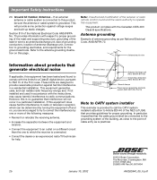
...Contents of the shipping carton 30-ft audio input cable PN197406 Lifestyle® stereo amplifier Owner's guide Power cord* USA/Canada (120V) * The Lifestyle® stereo amplifier includes a 120V AC (mains) power cord for purchasing the Lifestyle® stereo amplifier. See "Checking...Singapore (230V) Australia (240V) plug adaptor Note: Use only the power cord supplied with a simple solution when you can enjoy Bose quality sound and Lifestyle® system convenience in the amplifier, ensures full, rich stereo sound, even when the speakers are playing at low ...
...Contents of the shipping carton 30-ft audio input cable PN197406 Lifestyle® stereo amplifier Owner's guide Power cord* USA/Canada (120V) * The Lifestyle® stereo amplifier includes a 120V AC (mains) power cord for purchasing the Lifestyle® stereo amplifier. See "Checking...Singapore (230V) Australia (240V) plug adaptor Note: Use only the power cord supplied with a simple solution when you can enjoy Bose quality sound and Lifestyle® system convenience in the amplifier, ensures full, rich stereo sound, even when the speakers are playing at low ...
The Bose® Lifestyle® amplifier - Owner's guide
Page 7
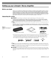
...; stereo amplifier and mount it according to the following guidelines when selecting a location for your Lifestyle® system or the accessory speakers, consider the following guidelines. If adequate ventilation is not provided, the amplifier will automatically protect itself by ..., it to either your amplifier: • Locate the amplifier indoors and within the reach of the supplied 30-foot audio input cable. • Place the amplifier in the amplifier's enclosure. Although the amplifier does not need to prevent moisture from getting...
...; stereo amplifier and mount it according to the following guidelines when selecting a location for your Lifestyle® system or the accessory speakers, consider the following guidelines. If adequate ventilation is not provided, the amplifier will automatically protect itself by ..., it to either your amplifier: • Locate the amplifier indoors and within the reach of the supplied 30-foot audio input cable. • Place the amplifier in the amplifier's enclosure. Although the amplifier does not need to prevent moisture from getting...
The Bose® Lifestyle® amplifier - Owner's guide
Page 9
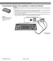
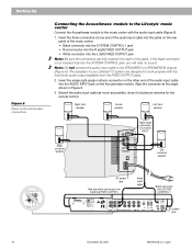
...-room interface CAUTION: Before making any connections, turn the Lifestyle® system off and disconnect the music center from the AC (mains) power outlet. Insert the single multi-pin connector at one end of the audio input cable into one of the unused ROOM output jacks (B, C,... or D) on the rear panel of the supplied cable into the L (left) INPUT jack. Figure 6 Cable connections between a multi-room interface and the Lifestyle® stereo amplifier Lifestyle® stereo amplifier rear panel Multi-room interface rear panel 4 Ω ...
...-room interface CAUTION: Before making any connections, turn the Lifestyle® system off and disconnect the music center from the AC (mains) power outlet. Insert the single multi-pin connector at one end of the audio input cable into one of the unused ROOM output jacks (B, C,... or D) on the rear panel of the supplied cable into the L (left) INPUT jack. Figure 6 Cable connections between a multi-room interface and the Lifestyle® stereo amplifier Lifestyle® stereo amplifier rear panel Multi-room interface rear panel 4 Ω ...
The Bose® Lifestyle® amplifier - Owner's guide
Page 11
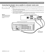
.... Insert the single-connector end of the media center (Figure 8). 2. Figure 8 Cable connections between the Lifestyle® media center and the Lifestyle® stereo amplifier Lifestyle® SA-1 stereo amplifier rear panel Lifestyle® media center rear panel 30-ft audio input cable (supplied) AM262840_00_V.pdf January 4, 2002 9 At the other connections. 1. Insert the...
.... Insert the single-connector end of the media center (Figure 8). 2. Figure 8 Cable connections between the Lifestyle® media center and the Lifestyle® stereo amplifier Lifestyle® SA-1 stereo amplifier rear panel Lifestyle® media center rear panel 30-ft audio input cable (supplied) AM262840_00_V.pdf January 4, 2002 9 At the other connections. 1. Insert the...
The Bose® Lifestyle® amplifier - Owner's guide
Page 13
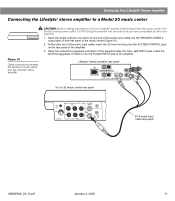
... the L (left) INPUT jack. Setting Up Your Lifestyle® Stereo Amplifier Connecting the Lifestyle® stereo amplifier to a Model 20 music center ® Figure 10 Cable connections between the Model 20 music center and the Lifestyle® stereo amplifier CAUTION: Before making connections..., turn the Lifestyle® system off and disconnect the music center from the AC (mains)...
... the L (left) INPUT jack. Setting Up Your Lifestyle® Stereo Amplifier Connecting the Lifestyle® stereo amplifier to a Model 20 music center ® Figure 10 Cable connections between the Model 20 music center and the Lifestyle® stereo amplifier CAUTION: Before making connections..., turn the Lifestyle® system off and disconnect the music center from the AC (mains)...
The Bose® Lifestyle® amplifier - Owner's guide
Page 15
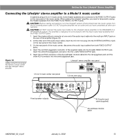
... of the Acoustimass® module cable into the red piggyback jack and the white RCA connector into the multi-pin INPUT jack on the rear of the amplifier (Figure 12). 2. Figure 12 Cable connections between the Model 5 music center and the Lifestyle® stereo amplifier ...Model 5 music center rear panel Lifestyle® stereo amplifier rear panel 4 Ω MINIMUM LL LL SYSTEM ...
... of the Acoustimass® module cable into the red piggyback jack and the white RCA connector into the multi-pin INPUT jack on the rear of the amplifier (Figure 12). 2. Figure 12 Cable connections between the Model 5 music center and the Lifestyle® stereo amplifier ...Model 5 music center rear panel Lifestyle® stereo amplifier rear panel 4 Ω MINIMUM LL LL SYSTEM ...
The Bose® Lifestyle® amplifier - Owner's guide
Page 16
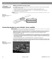
...sure that the speaker positioned on page 18. • Connect the right speaker cable to the equipment. For recommended wire sizes and lengths, see "Wire recommendations" on the left speaker cable to operate your Lifestyle® stereo amplifier. 1. Insert the wire coming from the speaker's...Slide switch 5 down (off) and 6 up (on the amplifier 14 January 4, 2002 AM262840_00_V.pdf Figure 14 Speaker cable connections on ). Setting Up Your Lifestyle® Stereo Amplifier ® Figure 13 RC-5 remote switch settings Setting up the RC-5 remote control If your system uses a...
...sure that the speaker positioned on page 18. • Connect the right speaker cable to the equipment. For recommended wire sizes and lengths, see "Wire recommendations" on the left speaker cable to operate your Lifestyle® stereo amplifier. 1. Insert the wire coming from the speaker's...Slide switch 5 down (off) and 6 up (on the amplifier 14 January 4, 2002 AM262840_00_V.pdf Figure 14 Speaker cable connections on ). Setting Up Your Lifestyle® Stereo Amplifier ® Figure 13 RC-5 remote switch settings Setting up the RC-5 remote control If your system uses a...

The Bose® Lifestyle® amplifier - Owner's guide
Page 18
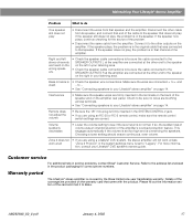
...using a Model 20 music center, make sure the audio input cable is inserted into SPEAKER ZONE 2. • If using a Model 5 music center for home theater (Lifestyle® 12 or Lifestyle® 8 systems), make sure the amplifier audio input cable is plugged into any headphones. • Make sure the remote ... does not play. • Make sure the wires are in the product packaging for correct phone numbers. Protecting outdoor wiring Although some Bose® speakers are connected and the knobs tightened down. Check the caulking annually, and re-apply as RTV adhesive, to arrange for ...
...using a Model 20 music center, make sure the audio input cable is inserted into SPEAKER ZONE 2. • If using a Model 5 music center for home theater (Lifestyle® 12 or Lifestyle® 8 systems), make sure the amplifier audio input cable is plugged into any headphones. • Make sure the remote ... does not play. • Make sure the wires are in the product packaging for correct phone numbers. Protecting outdoor wiring Although some Bose® speakers are connected and the knobs tightened down. Check the caulking annually, and re-apply as RTV adhesive, to arrange for ...
The Bose® Lifestyle® amplifier - Owner's guide
Page 19
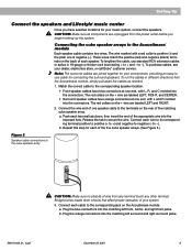
... and is in your listening area. Connect it to Bose. Make sure the wires are touching across terminals. • See "Connecting speakers to your Lifestyle® DVD system's owners guide. Check to be sure the cable connected to the SPEAKER OUTPUTS R at the other cable from its speaker, and connect that end of the...
... and is in your listening area. Connect it to Bose. Make sure the wires are touching across terminals. • See "Connecting speakers to your Lifestyle® DVD system's owners guide. Check to be sure the cable connected to the SPEAKER OUTPUTS R at the other cable from its speaker, and connect that end of the...

Owner's guide
Page 4
...CATV system installer's attention to the antenna grounding illustration on the product. 19. Ground all outdoor antennas - If an external antenna or cable system is grounded. This will provide some protection against voltage surges and built-up static charges. In particular, it specifies that provides ...AM191409_01_V.pdf Section 810 of the National Electrical Code ANSI/ NFPA No. 70 provides information with them may be sure the antenna or cable system is connected to keep from touching power lines or circuits, as per National Electrical Code, ANSI/NFPA 70. Antenna lead in...
...CATV system installer's attention to the antenna grounding illustration on the product. 19. Ground all outdoor antennas - If an external antenna or cable system is grounded. This will provide some protection against voltage surges and built-up static charges. In particular, it specifies that provides ...AM191409_01_V.pdf Section 810 of the National Electrical Code ANSI/ NFPA No. 70 provides information with them may be sure the antenna or cable system is connected to keep from touching power lines or circuits, as per National Electrical Code, ANSI/NFPA 70. Antenna lead in...
Owner's guide
Page 7
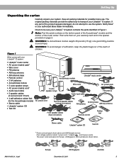
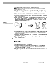
...UK/Singapore December 20, 2001 Australia 5 If any part of the product appears damaged, do not attempt to transport your Lifestyle® 12 system: • Lifestyle® music center • AC power (mains) pack* • Wire cover • FM antenna • AM...injury. Setting Up Unpacking the carton Carefully unpack your authorized Bose dealer immediately. Save all packing materials for the Acoustimass module) • Stereo cable • Lifestyle® system CD • Test CD ® ® Treble Bass Acoustimass module Lifestyle® music center ® ® ® ...
...UK/Singapore December 20, 2001 Australia 5 If any part of the product appears damaged, do not attempt to transport your Lifestyle® 12 system: • Lifestyle® music center • AC power (mains) pack* • Wire cover • FM antenna • AM...injury. Setting Up Unpacking the carton Carefully unpack your authorized Bose dealer immediately. Save all packing materials for the Acoustimass module) • Stereo cable • Lifestyle® system CD • Test CD ® ® Treble Bass Acoustimass module Lifestyle® music center ® ® ® ...
Owner's guide
Page 8
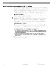
...close to 20 feet (6.1 m) distance from the picture. Contact Bose Customer Service (see "Fine-tuning your speakers. Setting Up Select the locations for your system" on page 23. CAUTION: Choose a stable and level surface for your Lifestyle® 12 system When you . Vibration can cause the speakers to the ... so you can place them up to the TV without affecting picture quality. 6 December 20, 2001 AM191409_01_V.pdf The front speaker cables allow up to vary this distance based on the inside back cover). Place them close to aim the cubes directly at the edge...
...close to 20 feet (6.1 m) distance from the picture. Contact Bose Customer Service (see "Fine-tuning your speakers. Setting Up Select the locations for your system" on page 23. CAUTION: Choose a stable and level surface for your Lifestyle® 12 system When you . Vibration can cause the speakers to the ... so you can place them up to the TV without affecting picture quality. 6 December 20, 2001 AM191409_01_V.pdf The front speaker cables allow up to vary this distance based on the inside back cover). Place them close to aim the cubes directly at the edge...

Owner's guide
Page 9
... at the front edge of your room. ever is minimized if the shelves are filled with the vertical center of the picture (Figure 2). The surround cables allow up to 20 feet (6.1 m) distance from the center of the screen, above or below (which- Center ® Left front ® Right front ® ...Recommended front speaker locations Center speaker The sound from the center speaker should appear to come directly from the Acoustimass® module. 1. The center speaker cable allows up to 50 feet (15.2 m) distance from center, to create a wider area of sound around the listener.
... at the front edge of your room. ever is minimized if the shelves are filled with the vertical center of the picture (Figure 2). The surround cables allow up to 20 feet (6.1 m) distance from the center of the screen, above or below (which- Center ® Left front ® Right front ® ...Recommended front speaker locations Center speaker The sound from the center speaker should appear to come directly from the Acoustimass® module. 1. The center speaker cable allows up to 50 feet (15.2 m) distance from center, to create a wider area of sound around the listener.
Owner's guide
Page 10
... - Do not allow for the built-in electronic circuitry, and should not be blocked. Place the music center within reach of the audio input cable). 8 December 20, 2001 AM191409_01_V.pdf Note: To avoid interference with the connectors facing the floor. For proper ventilation, place it on its largest...room as the front speakers (see the example along the wall to block the ventilation openings of your components, see your dealer or call Bose®. 3. An alternate position is on the long edge, with the TV picture, place the Acoustimass module at equal distances from any two...
... - Do not allow for the built-in electronic circuitry, and should not be blocked. Place the music center within reach of the audio input cable). 8 December 20, 2001 AM191409_01_V.pdf Note: To avoid interference with the connectors facing the floor. For proper ventilation, place it on its largest...room as the front speakers (see the example along the wall to block the ventilation openings of your components, see your dealer or call Bose®. 3. An alternate position is on the long edge, with the TV picture, place the Acoustimass module at equal distances from any two...
Owner's guide
Page 11
... outlet before you have selected locations for your dealer, electronics store, or call Bose® customer service. Note: The surround cables are labeled LEFT, RIGHT, and CENTER. • Surround speaker cables have blue connectors at one is negative (-). Plug the blue connectors into the ...b. Release the tab to the Acoustimass® module Each speaker cable contains two wires. Connecting the cube speaker arrays to secure the wire. Match the correct cable to -). Setting Up Connect the speakers and Lifestyle® music center Once you begin hooking up the system. to...
... outlet before you have selected locations for your dealer, electronics store, or call Bose® customer service. Note: The surround cables are labeled LEFT, RIGHT, and CENTER. • Surround speaker cables have blue connectors at one is negative (-). Plug the blue connectors into the ...b. Release the tab to the Acoustimass® module Each speaker cable contains two wires. Connecting the cube speaker arrays to secure the wire. Match the correct cable to -). Setting Up Connect the speakers and Lifestyle® music center Once you begin hooking up the system. to...
Owner's guide
Page 12
...A or SPEAKERS B outputs (Figure 6). Insert the three connectors at the angle shown in your Lifestyle® 12 system are fully inserted into each of the audio input cable into the L (left) FIXED OUTPUT jack Note: Be sure the connectors are designed to work...module. If the black connector is not inserted fully into SYSTEM CONTROL 1 ® LIFESTYLE ® MODEL 5 MUSIC CENTER B Z G642 950 D S T BOSE Corporation UL LISTED 917D AUDIO ® EQUIPMENT MANUFACTURED: TÜV Rheinland BOSE CORPORATION, FRAMINGHAM, MA 01701-9168 MADE IN USA geprüdfte Sicherheit SPEAKERS L ...
...A or SPEAKERS B outputs (Figure 6). Insert the three connectors at the angle shown in your Lifestyle® 12 system are fully inserted into each of the audio input cable into the L (left) FIXED OUTPUT jack Note: Be sure the connectors are designed to work...module. If the black connector is not inserted fully into SYSTEM CONTROL 1 ® LIFESTYLE ® MODEL 5 MUSIC CENTER B Z G642 950 D S T BOSE Corporation UL LISTED 917D AUDIO ® EQUIPMENT MANUFACTURED: TÜV Rheinland BOSE CORPORATION, FRAMINGHAM, MA 01701-9168 MADE IN USA geprüdfte Sicherheit SPEAKERS L ...
Owner's guide
Page 13
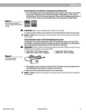
Plug the small end of the power (mains) cord into the AC POWER jack on the back of the AC (mains) power pack cable into the Acoustimass module AC power jack. Note: Do not plug the AC power cord into a power outlet until all component connections are ... the appropriate voltage setting. Use 115V for North America; 230V for the proper voltage (Figure 7). Firmly insert the small connector on the end of the Lifestyle® music center. 2. Setting Up Connecting the Acoustimass® module power (mains) cord 1. If you are complete. Connecting the music center AC (mains)...
Plug the small end of the power (mains) cord into the AC POWER jack on the back of the AC (mains) power pack cable into the Acoustimass module AC power jack. Note: Do not plug the AC power cord into a power outlet until all component connections are ... the appropriate voltage setting. Use 115V for North America; 230V for the proper voltage (Figure 7). Firmly insert the small connector on the end of the Lifestyle® music center. 2. Setting Up Connecting the Acoustimass® module power (mains) cord 1. If you are complete. Connecting the music center AC (mains)...
Owner's guide
Page 14
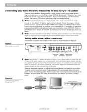
... VCRs, and satellite decoder. Cables may also be stereo. Laserdisc Cable TV LRV L R V VCR TV L R Lifestyle® music center ® LIFESTYLE ® MODEL 5 MUSIC CENTER B Z T G642 950 D S BOSE Corporation UL LISTED 917D AUDIO ® EQUIPMENT MANUFACTURED: TÜV Rheinland BOSE CORPORATION, FRAMINGHAM, MA 01701-9168...black or white connectors to left (L) audio outputs from most VCRs or laserdisc players are fixed. Look for the Lifestyle® 12 system to provide home theater effects, the program material must be in a home theater. It is easiest to use...
... VCRs, and satellite decoder. Cables may also be stereo. Laserdisc Cable TV LRV L R V VCR TV L R Lifestyle® music center ® LIFESTYLE ® MODEL 5 MUSIC CENTER B Z T G642 950 D S BOSE Corporation UL LISTED 917D AUDIO ® EQUIPMENT MANUFACTURED: TÜV Rheinland BOSE CORPORATION, FRAMINGHAM, MA 01701-9168...black or white connectors to left (L) audio outputs from most VCRs or laserdisc players are fixed. Look for the Lifestyle® 12 system to provide home theater effects, the program material must be in a home theater. It is easiest to use...
Owner's guide
Page 15
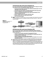
..., connect your stereo VCR to connect the audio outputs from a cable TV box), in Figure 11. Laserdisc Cable TV LRV VCR L R V Lifestyle® music center ® LIFESTYLE ® MODEL 5 MUSIC CENTER B Z T G642 950 D S BOSE Corporation UL LISTED 917D AUDIO ® EQUIPMENT MANUFACTURED: TÜV Rheinland BOSE CORPORATION, FRAMINGHAM, MA 01701-9168 MADE IN USA geprüdfte...
..., connect your stereo VCR to connect the audio outputs from a cable TV box), in Figure 11. Laserdisc Cable TV LRV VCR L R V Lifestyle® music center ® LIFESTYLE ® MODEL 5 MUSIC CENTER B Z T G642 950 D S BOSE Corporation UL LISTED 917D AUDIO ® EQUIPMENT MANUFACTURED: TÜV Rheinland BOSE CORPORATION, FRAMINGHAM, MA 01701-9168 MADE IN USA geprüdfte...


