The Bose® Lifestyle® amplifier - Owner's guide
Page 9
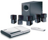
...; stereo amplifier Lifestyle® stereo amplifier rear panel Multi-room interface rear panel 4 Ω MINIMUM LL R L SYSTEM RR CONTROL L R +- At the other end of the amplifier. 3. Insert the white RCA piggyback connector of the supplied cable into the R (right) INPUT jack of the multi-room interface...
...; stereo amplifier Lifestyle® stereo amplifier rear panel Multi-room interface rear panel 4 Ω MINIMUM LL R L SYSTEM RR CONTROL L R +- At the other end of the amplifier. 3. Insert the white RCA piggyback connector of the supplied cable into the R (right) INPUT jack of the multi-room interface...
The Bose® Lifestyle® amplifier - Owner's guide
Page 11
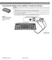
... L (left) INPUT jack. Setting Up Your Lifestyle® Stereo Amplifier Connecting the Lifestyle® stereo amplifier to a Lifestyle® media center CAUTION: Before making connections, turn the Lifestyle® system off and disconnect the media center from the AC (mains) power outlet. Insert the single-connector end of the amplifier. 3. Insert...
... L (left) INPUT jack. Setting Up Your Lifestyle® Stereo Amplifier Connecting the Lifestyle® stereo amplifier to a Lifestyle® media center CAUTION: Before making connections, turn the Lifestyle® system off and disconnect the media center from the AC (mains) power outlet. Insert the single-connector end of the amplifier. 3. Insert...
The Bose® Lifestyle® amplifier - Owner's guide
Page 13
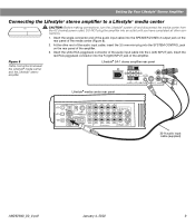
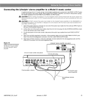
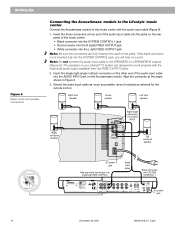
...OUTPUTS INPUT Model 20 music center rear panel 30-ft audio input cable (supplied) AM262840_00_V.pdf January 4, 2002 11 Insert the single multi-pin connector at one end of the audio input cable into the SYSTEM CONTROL jack on the rear panel of the amplifier. 3. Insert the ...white RCA piggyback connector of the amplifier. Setting Up Your Lifestyle® Stereo Amplifier Connecting the Lifestyle® stereo amplifier to a Model 20 music center ® Figure 10 Cable connections between...
...OUTPUTS INPUT Model 20 music center rear panel 30-ft audio input cable (supplied) AM262840_00_V.pdf January 4, 2002 11 Insert the single multi-pin connector at one end of the audio input cable into the SYSTEM CONTROL jack on the rear panel of the amplifier. 3. Insert the ...white RCA piggyback connector of the amplifier. Setting Up Your Lifestyle® Stereo Amplifier Connecting the Lifestyle® stereo amplifier to a Model 20 music center ® Figure 10 Cable connections between...
The Bose® Lifestyle® amplifier - Owner's guide
Page 15
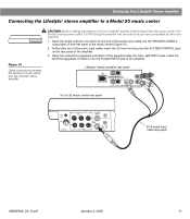
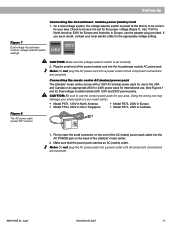
... into the red piggyback jack and the white RCA connector into the L (left) FIXED OUTPUT jack. 5. Figure 12 Cable connections between the Model 5 music center and the Lifestyle® stereo amplifier Model 5 music center rear panel Lifestyle® stereo amplifier rear panel 4 &#...audio input cable (supplied) Acoustimass module cable AM262840_00_V.pdf January 4, 2002 13 Insert the red RCA piggyback connector of the amplifier (Figure 12). 2. When adding the Lifestyle® amplifier, you have completed all other end of the audio input cable, insert the ...
... into the red piggyback jack and the white RCA connector into the L (left) FIXED OUTPUT jack. 5. Figure 12 Cable connections between the Model 5 music center and the Lifestyle® stereo amplifier Model 5 music center rear panel Lifestyle® stereo amplifier rear panel 4 &#...audio input cable (supplied) Acoustimass module cable AM262840_00_V.pdf January 4, 2002 13 Insert the red RCA piggyback connector of the amplifier (Figure 12). 2. When adding the Lifestyle® amplifier, you have completed all other end of the audio input cable, insert the ...
The Bose® Lifestyle® amplifier - Owner's guide
Page 17
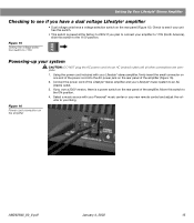
... you plan to connect your amplifier to 115V (North America), slide this switch to 115V Powering-up your Lifestyle® stereo amplifier, firmly insert the small connector on one end of the power cord into an AC (mains) outlet until all other connections are complete. 1. Select ...switch. • This switch is a power switch on the rear panel of the amplifier. Check to see if you have a dual voltage Lifestyle® amplifier • Dual voltage units have a voltage selection switch on the amplifier AM262840_00_V.pdf January 4, 2002 15 Figure 16 ...
... you plan to connect your amplifier to 115V (North America), slide this switch to 115V Powering-up your Lifestyle® stereo amplifier, firmly insert the small connector on one end of the power cord into an AC (mains) outlet until all other connections are complete. 1. Select ...switch. • This switch is a power switch on the rear panel of the amplifier. Check to see if you have a dual voltage Lifestyle® amplifier • Dual voltage units have a voltage selection switch on the amplifier AM262840_00_V.pdf January 4, 2002 15 Figure 16 ...
The Bose® Lifestyle® amplifier - Owner's guide
Page 20
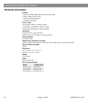
...W x 51/2 in . Signal to 15 kHz, with no more than 0.5% THD. D x 31/8 in . Maintaining Your Lifestyle® Stereo Amplifier Technical information Features • Bose® proprietary digital signal processing technology • Built-in digital volume control • Thermal overload protection • Protective rubber feet ... 220-240V 50/60 Hz, 220W Input jacks Dual audio: RCA or 8-pin mini-DIN System control: 3.5 mm stereo mini-plug connector Input sensitivity 0.5 Vrms @ 1 kHz Output power (continuous average) 35W per channel minimum into 4 Ohms, from 30 to Noise ratio (S/N)...
...W x 51/2 in . Signal to 15 kHz, with no more than 0.5% THD. D x 31/8 in . Maintaining Your Lifestyle® Stereo Amplifier Technical information Features • Bose® proprietary digital signal processing technology • Built-in digital volume control • Thermal overload protection • Protective rubber feet ... 220-240V 50/60 Hz, 220W Input jacks Dual audio: RCA or 8-pin mini-DIN System control: 3.5 mm stereo mini-plug connector Input sensitivity 0.5 Vrms @ 1 kHz Output power (continuous average) 35W per channel minimum into 4 Ohms, from 30 to Noise ratio (S/N)...
Owner's guide
Page 7
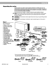
...use the system. Notify Bose® or your system. WARNING: he Acoustimass module weighs 33 pounds (15 kg). The original packing materials provide the safest way to use . Note: Find the serial numbers on your Lifestyle® 12 system: • Lifestyle® music center •...AC power pack FM antenna AC power cord Surround speaker cables (orange connectors) Front speaker cables (blue connectors) Antenna base AA batteries AM loop antenna + - Use good lifting practice to be sure your Lifestyle® 12 system. Dual voltage systems include 1 power cord, 1 adapter , and...
...use the system. Notify Bose® or your system. WARNING: he Acoustimass module weighs 33 pounds (15 kg). The original packing materials provide the safest way to use . Note: Find the serial numbers on your Lifestyle® 12 system: • Lifestyle® music center •...AC power pack FM antenna AC power cord Surround speaker cables (orange connectors) Front speaker cables (blue connectors) Antenna base AA batteries AM loop antenna + - Use good lifting practice to be sure your Lifestyle® 12 system. Dual voltage systems include 1 power cord, 1 adapter , and...
Owner's guide
Page 10
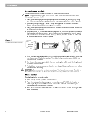
... Bass Alternate position ® RIGHT REAR LEFT REAR RIGHT FRONT CENTER LEFT FRONT CUOBUETSPPUETASKTEORS ® 5. An alternate position is on the long edge, with the connectors facing the floor. The rubber feet provide increased stability and protection from a wall and the ceiling. Music center Select a location for the Acoustimass module (Figure... additional audio and/or video cables to connect all of the Acoustimass module. CAUTION: Do not cover the ventilation openings of your dealer or call Bose®. 3. If you have selected a position for the Acoustimass module.
... Bass Alternate position ® RIGHT REAR LEFT REAR RIGHT FRONT CENTER LEFT FRONT CUOBUETSPPUETASKTEORS ® 5. An alternate position is on the long edge, with the connectors facing the floor. The rubber feet provide increased stability and protection from a wall and the ceiling. Music center Select a location for the Acoustimass module (Figure... additional audio and/or video cables to connect all of the Acoustimass module. CAUTION: Do not cover the ventilation openings of your dealer or call Bose®. 3. If you have selected a position for the Acoustimass module.
Owner's guide
Page 11
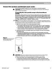
...Lifestyle® music center Once you begin hooking up the system. CAUTION: Make sure all components are joined together for your system. 3. to secure the wire. To run the cables in 18-gauge or thicker cord (connecting + to the corresponding speaker location. • Front speaker cables have blue connectors...are labeled LEFT, RIGHT, and CENTER. • Surround speaker cables have selected locations for your dealer, electronics store, or call Bose® customer service. Push each of the five cube speaker arrays. (See Figure 5.) Figure 5 Speaker cable connections to the terminals...
...Lifestyle® music center Once you begin hooking up the system. CAUTION: Make sure all components are joined together for your system. 3. to secure the wire. To run the cables in 18-gauge or thicker cord (connecting + to the corresponding speaker location. • Front speaker cables have blue connectors...are labeled LEFT, RIGHT, and CENTER. • Surround speaker cables have selected locations for your dealer, electronics store, or call Bose® customer service. Push each of the five cube speaker arrays. (See Figure 5.) Figure 5 Speaker cable connections to the terminals...
Owner's guide
Page 12
If the black connector is not inserted fully into SYSTEM CONTROL 1 ® LIFESTYLE ® MODEL 5 MUSIC CENTER B Z G642 950 D S T BOSE Corporation UL LISTED 917D AUDIO ® EQUIPMENT MANUFACTURED: TÜV Rheinland BOSE CORPORATION, FRAMINGHAM, MA 01701-9168 MADE IN USA geprüdfte Sicherheit SPEAKERS L FIXED R 93...1.0A 2 AC power jack 10 December 20, 2001 AM191409_01_V.pdf Align the connector at one end of the jacks. Insert the three connectors at the angle shown in your Lifestyle® 12 system are fully inserted into the L (left) FIXED OUTPUT jack Note: Be...
If the black connector is not inserted fully into SYSTEM CONTROL 1 ® LIFESTYLE ® MODEL 5 MUSIC CENTER B Z G642 950 D S T BOSE Corporation UL LISTED 917D AUDIO ® EQUIPMENT MANUFACTURED: TÜV Rheinland BOSE CORPORATION, FRAMINGHAM, MA 01701-9168 MADE IN USA geprüdfte Sicherheit SPEAKERS L FIXED R 93...1.0A 2 AC power jack 10 December 20, 2001 AM191409_01_V.pdf Align the connector at one end of the jacks. Insert the three connectors at the angle shown in your Lifestyle® 12 system are fully inserted into the L (left) FIXED OUTPUT jack Note: Be...
Owner's guide
Page 13
...230V power packs. Plug the small end of the power (mains) cord into the AC POWER jack on the end of the Lifestyle® music center. 2. Firmly insert the small connector on the back of the AC (mains) power pack cable into the Acoustimass module AC power jack. Figure 7 Dual voltage ...power pack reaches an AC (mains) outlet. Use 115V for North America; 230V for your area. Connecting the music center AC (mains) power pack The Lifestyle® music center comes with a 120V AC (mains) power pack for the proper voltage (Figure 7). Check to be correct for Europe and Australia. Setting...
...230V power packs. Plug the small end of the power (mains) cord into the AC POWER jack on the end of the Lifestyle® music center. 2. Firmly insert the small connector on the back of the AC (mains) power pack cable into the Acoustimass module AC power jack. Figure 7 Dual voltage ...power pack reaches an AC (mains) outlet. Use 115V for North America; 230V for your area. Connecting the music center AC (mains) power pack The Lifestyle® music center comes with a 120V AC (mains) power pack for the proper voltage (Figure 7). Check to be correct for Europe and Australia. Setting...
Owner's guide
Page 14
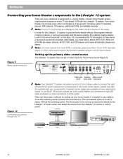
... CDI players and nearly all laserdisc players are color coded. Figure 9 Music center connectors ® LIFESTYLE ® MODEL 5 MUSIC CENTER B Z T G642 950 D S BOSE Corporation UL LISTED 917D AUDIO ® EQUIPMENT MANUFACTURED: TÜV Rheinland BOSE CORPORATION, FRAMINGHAM, MA 01701-9168 MADE IN USA geprüdfte Sicherheit SPEAKERS ... TV and stereo VCR with your components. Note: A mono TV only serves as a display for the Lifestyle® 12 system to the Lifestyle® 12 music center, and select the source from a component to the music center inputs. To hear stereo or ...
... CDI players and nearly all laserdisc players are color coded. Figure 9 Music center connectors ® LIFESTYLE ® MODEL 5 MUSIC CENTER B Z T G642 950 D S BOSE Corporation UL LISTED 917D AUDIO ® EQUIPMENT MANUFACTURED: TÜV Rheinland BOSE CORPORATION, FRAMINGHAM, MA 01701-9168 MADE IN USA geprüdfte Sicherheit SPEAKERS ... TV and stereo VCR with your components. Note: A mono TV only serves as a display for the Lifestyle® 12 system to the Lifestyle® 12 music center, and select the source from a component to the music center inputs. To hear stereo or ...
Owner's guide
Page 18
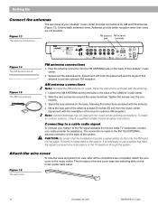
.... Figure 13 The antenna connections FM antenna AM antenna jack terminals ® LIFESTYLE ® MODEL 5 MUSIC CENTER B Z G642 950 D S T BOSE Corporation UL LISTED 917D AUDIO ® EQUIPMENT MANUFACTURED: TÜV Rheinland BOSE CORPORATION, FRAMINGHAM, MA 01701-9168 MADE IN USA geprüdfte Sicherheit SPEAKERS...dipole antenna Figure 15 The AM loop antenna FM antenna connections 1. Slide the wire connectors around the screw terminals. Connecting to prevent any re-emissions of your Lifestyle® music center provides connections for AM and FM antennas (Figure 13). The ...
.... Figure 13 The antenna connections FM antenna AM antenna jack terminals ® LIFESTYLE ® MODEL 5 MUSIC CENTER B Z G642 950 D S T BOSE Corporation UL LISTED 917D AUDIO ® EQUIPMENT MANUFACTURED: TÜV Rheinland BOSE CORPORATION, FRAMINGHAM, MA 01701-9168 MADE IN USA geprüdfte Sicherheit SPEAKERS...dipole antenna Figure 15 The AM loop antenna FM antenna connections 1. Slide the wire connectors around the screw terminals. Connecting to prevent any re-emissions of your Lifestyle® music center provides connections for AM and FM antennas (Figure 13). The ...
Owner's guide
Page 28
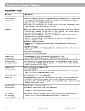
... 20, 2001 AM191409_01_V.pdf This allows the unit to reset itself , or acts erratically What to do • Make sure the power connector is plugged securely into the music center, the Acoustimass® module power cord is plugged securely into the module, and the power pack and... input cable is connected to the music center FIXED outputs, the black connector is fully seated in the music center SYSTEM CONTROL 1 jack, and the multi-pin connector is firmly seated in the display. Maintaining Your Lifestyle® 12 System Troubleshooting Problem System does not function at both ends. •...
... 20, 2001 AM191409_01_V.pdf This allows the unit to reset itself , or acts erratically What to do • Make sure the power connector is plugged securely into the music center, the Acoustimass® module power cord is plugged securely into the module, and the power pack and... input cable is connected to the music center FIXED outputs, the black connector is fully seated in the music center SYSTEM CONTROL 1 jack, and the multi-pin connector is firmly seated in the display. Maintaining Your Lifestyle® 12 System Troubleshooting Problem System does not function at both ends. •...
Owner's guide
Page 32
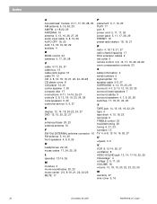
... 13, 18, 19, 23, 24, 29 cube speakers 6, 29 customer service 6, 9, 27 D display 12, 14, 18, 20-22, 24, 27 DVD 12, 15, 20, 22, 27 E enhanced bass 20, 23 external antenna 16 F FM 75Ω EXTERNAL antenna connector 16 FM antenna 5, 16, 29 front speakers 4, 6, 8, 26 H headphones 22, 26 house codes 17..., 24, 25, 26 L laserdisc 12-14, 26 M moisture 2 movie soundtracks 20, 23 music center 2-5, 8-19, 21, 22, 24-29 MUTE 17...
... 13, 18, 19, 23, 24, 29 cube speakers 6, 29 customer service 6, 9, 27 D display 12, 14, 18, 20-22, 24, 27 DVD 12, 15, 20, 22, 27 E enhanced bass 20, 23 external antenna 16 F FM 75Ω EXTERNAL antenna connector 16 FM antenna 5, 16, 29 front speakers 4, 6, 8, 26 H headphones 22, 26 house codes 17..., 24, 25, 26 L laserdisc 12-14, 26 M moisture 2 movie soundtracks 20, 23 music center 2-5, 8-19, 21, 22, 24-29 MUTE 17...


