
Setup Manual
Page 2
... 1: Introduction 1 1.1 Before You Start 1 1.2 Package Checklist 1 1.3 Motherboard Features 2 1.4 Rear Panel Connectors 3 1.5 Motherboard Layout 4 Chapter 2: Hardware Installation 5 2.1 Installing Central Processing Unit (CPU 5 2.2 FAN Headers 6 2.3 Installing System Memory 8 2.4 Connectors and Slots 10 Chapter 3: Headers & Jumpers Setup 12 3.1 How to Setup Jumpers 12 3.2 Detail Settings 12 Chapter 4: NVIDIA RAID Functions 22 4.1 Operation System 22...
... 1: Introduction 1 1.1 Before You Start 1 1.2 Package Checklist 1 1.3 Motherboard Features 2 1.4 Rear Panel Connectors 3 1.5 Motherboard Layout 4 Chapter 2: Hardware Installation 5 2.1 Installing Central Processing Unit (CPU 5 2.2 FAN Headers 6 2.3 Installing System Memory 8 2.4 Connectors and Slots 10 Chapter 3: Headers & Jumpers Setup 12 3.1 How to Setup Jumpers 12 3.2 Detail Settings 12 Chapter 4: NVIDIA RAID Functions 22 4.1 Operation System 22...
Setup Manual
Page 4
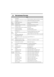
...front panel facilities Front Audio Connector x1 Supports front panel audio function CD-in Connector x1 Supports CD audio-in GeForce 6100 Chipset Max Shared Video Memory is not supported Integrated IDE Controller IDE Ultra DMA 33 / 66 / 100 / 133 Bus Master supports PIO ... MOTHERBOARD FEATURES SPEC Socket AM2 AMD 64 Architecture enables 32 and 64 bit computing CPU AMD Athlon 64 / Athlon 64 FX / Sempron Supports Hyper Transport and Cool=n=Quiet processors FSB Support HyperTransport Supports up to 1000 MHz Bandwidth Chipset GeForce 6100 nForce 410 Graphics Integrated in...
...front panel facilities Front Audio Connector x1 Supports front panel audio function CD-in Connector x1 Supports CD audio-in GeForce 6100 Chipset Max Shared Video Memory is not supported Integrated IDE Controller IDE Ultra DMA 33 / 66 / 100 / 133 Bus Master supports PIO ... MOTHERBOARD FEATURES SPEC Socket AM2 AMD 64 Architecture enables 32 and 64 bit computing CPU AMD Athlon 64 / Athlon 64 FX / Sempron Supports Hyper Transport and Cool=n=Quiet processors FSB Support HyperTransport Supports up to 1000 MHz Bandwidth Chipset GeForce 6100 nForce 410 Graphics Integrated in...
Setup Manual
Page 10
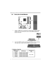
Insert the DIMM vertically and firmly into the slot until the retaining chip snap back in place and the DIMM is 4GB. 8 Unlock a DIMM slot by pressing the retaining clips outward. B. Align a DIMM on the slot such that the notch on the DIMM matches the break on the Slot. 2. Memory Capacity DIMM Socket Location DDR Module DIMMA1 256MB/512MB/1024MB DIMMB1 256MB/512MB/1024MB DIMMA2 256MB/512MB/1024MB DIMMB2 256MB/512MB/1024MB Total Memory Size Max is properly seated. Motherboard Manual 2.3 INSTALLING SYSTEM MEMORY 1.
Insert the DIMM vertically and firmly into the slot until the retaining chip snap back in place and the DIMM is 4GB. 8 Unlock a DIMM slot by pressing the retaining clips outward. B. Align a DIMM on the slot such that the notch on the DIMM matches the break on the Slot. 2. Memory Capacity DIMM Socket Location DDR Module DIMMA1 256MB/512MB/1024MB DIMMB1 256MB/512MB/1024MB DIMMA2 256MB/512MB/1024MB DIMMB2 256MB/512MB/1024MB Total Memory Size Max is properly seated. Motherboard Manual 2.3 INSTALLING SYSTEM MEMORY 1.
Setup Manual
Page 11
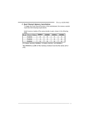
TForce 6100 AM2 C. Duual Channel Status DIMMA1 DIMMB1 DIMMA2 DIMMB2 Enabled O O X X Enabled X X O O Enabled O O O O (O means memory installed, X means memory not installed.) The DRAM bus width of the same density in pairs, shown in the following requirements: Install memory module of the memory module must meet the following table. Dual Channel Memory installation To trigger the Dual Channel function of the motherboard, the memory module must be the same (x8 or x16) 9
TForce 6100 AM2 C. Duual Channel Status DIMMA1 DIMMB1 DIMMA2 DIMMB2 Enabled O O X X Enabled X X O O Enabled O O O O (O means memory installed, X means memory not installed.) The DRAM bus width of the same density in pairs, shown in the following requirements: Install memory module of the memory module must meet the following table. Dual Channel Memory installation To trigger the Dual Channel function of the motherboard, the memory module must be the same (x8 or x16) 9
Setup Manual
Page 21
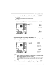
... are powered with +5V standby voltage. 13 Pin 1-2 close 13 Pin 2-3 close Header to adjust Memory Voltage: JDDR_II>2.2V When adjusting Memory Voltage, please place the jumper to support 2.2V. (Consulting your DDR supplier) 19 TForce 6100 AM2 Power Source Selection Headers for Keyboard/Mouse: JKBMSV1 Pin 1-2 Close: JKBMSV1: +5V for PS/2 keyboard and mouse...
... are powered with +5V standby voltage. 13 Pin 1-2 close 13 Pin 2-3 close Header to adjust Memory Voltage: JDDR_II>2.2V When adjusting Memory Voltage, please place the jumper to support 2.2V. (Consulting your DDR supplier) 19 TForce 6100 AM2 Power Source Selection Headers for Keyboard/Mouse: JKBMSV1 Pin 1-2 Close: JKBMSV1: +5V for PS/2 keyboard and mouse...
Setup Manual
Page 26
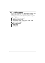
...Overclocking Navigator Engine (O.N.E.) CMOS Reloading Program (C.R.P.) Memory Integration Test (M.I.T., under Overclock Navigator Engine) Integrated Flash Program (I.F.P.) Smart Fan Function (under BIOS or Windows interface, T-Power is designed for overclock users. Based on many precise tests, Biostar Engineering Team (BET) has developed this ultimate...: Hardware Monitor Overclock Engine Smart Fan Function Life Update 24 Motherboard Manual 5.1: T-POWER INTRODUCTION Biostar T-Power is a whole new utility that is able to present the best system state according to raise system performance.
...Overclocking Navigator Engine (O.N.E.) CMOS Reloading Program (C.R.P.) Memory Integration Test (M.I.T., under Overclock Navigator Engine) Integrated Flash Program (I.F.P.) Smart Fan Function (under BIOS or Windows interface, T-Power is designed for overclock users. Based on many precise tests, Biostar Engineering Team (BET) has developed this ultimate...: Hardware Monitor Overclock Engine Smart Fan Function Life Update 24 Motherboard Manual 5.1: T-POWER INTRODUCTION Biostar T-Power is a whole new utility that is able to present the best system state according to raise system performance.
Setup Manual
Page 28
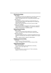
...). Choices: 1.52V, 1.60V, 1.68V, 1.76V. Motherboard Manual CPU Overclock Setting: CPU Voltage: This function will increase memory stability when overclocking. Hammer CPU Multiplier: The MOS allows users to increase VGA card performance. Memory Overclock Setting: Memory Voltage: This function will increase CPU stability when overclocking. Choices: DDR400, DDR 533, DDR 667, DDR 800...
...). Choices: 1.52V, 1.60V, 1.68V, 1.76V. Motherboard Manual CPU Overclock Setting: CPU Voltage: This function will increase memory stability when overclocking. Hammer CPU Multiplier: The MOS allows users to increase VGA card performance. Memory Overclock Setting: Memory Voltage: This function will increase CPU stability when overclocking. Choices: DDR400, DDR 533, DDR 667, DDR 800...
Setup Manual
Page 31
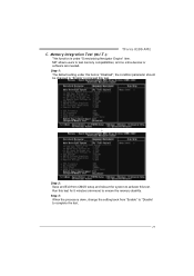
...; Step 2: Save and Exit from "Enable" to "Disable" to complete the test. 29 Run this test. Step 1: The default setting under "Overclocking Navigator Engine" item. TForce 6100 AM2 C. Memory Integration Test (M.I.T.): This function is under this item is done, change the setting back from CMOS setup and reboot the system to activate this test...
...; Step 2: Save and Exit from "Enable" to "Disable" to complete the test. 29 Run this test. Step 1: The default setting under "Overclocking Navigator Engine" item. TForce 6100 AM2 C. Memory Integration Test (M.I.T.): This function is under this item is done, change the setting back from CMOS setup and reboot the system to activate this test...
Setup Manual
Page 39
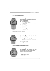
... function helps to increase VGA card performance. Range: 100MHz~150MHz. B. A. B. Interval: 1. CPU Overclocking Settings: TForce 6100 AM2 By adjusting can configure three items for Memory overclocking. CPU Ratio Range: 4~25. Memory Overclocking Settings: By adjusting can configure VGA card overclocking. Memory Clock Frequency Choices: 100, 133, 200, 266, 333, 400, 533, 667, 800. Interval: 1MHz. C. Interval...
... function helps to increase VGA card performance. Range: 100MHz~150MHz. B. A. B. Interval: 1. CPU Overclocking Settings: TForce 6100 AM2 By adjusting can configure three items for Memory overclocking. CPU Ratio Range: 4~25. Memory Overclocking Settings: By adjusting can configure VGA card overclocking. Memory Clock Frequency Choices: 100, 133, 200, 266, 333, 400, 533, 667, 800. Interval: 1MHz. C. Interval...
Setup Manual
Page 45
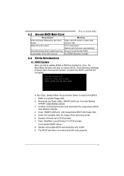
...Case, please follow the procedure below to update BIOS or BIOS is shown after boot-up No error found or video card beeps memory bad High-low siren sound CPU overheated System will shut down automatically One Short beep when system boot-up the system, it means...prompt. 7. BIOS Update After you fail to restore the BIOS: 1. TForce 6100 AM2 6.2 AWARD BIOS BEEP CODE Beep Sound Meaning One long beep followed by virus, the Boot-Block function will work properly. 43 Confirm motherboard model and download the respectively BIOS from the Biostar website: www.biostar.com.tw 3.
...Case, please follow the procedure below to update BIOS or BIOS is shown after boot-up No error found or video card beeps memory bad High-low siren sound CPU overheated System will shut down automatically One Short beep when system boot-up the system, it means...prompt. 7. BIOS Update After you fail to restore the BIOS: 1. TForce 6100 AM2 6.2 AWARD BIOS BEEP CODE Beep Sound Meaning One long beep followed by virus, the Boot-Block function will work properly. 43 Confirm motherboard model and download the respectively BIOS from the Biostar website: www.biostar.com.tw 3.
Setup Manual
Page 71
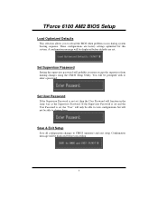
TForce 6100 AM2 BIOS Setup Load Optimized Defaults This selection allows you to CMOS (memory) and exit setup. If the Supervisor Password is set and the User Password is not set, then the User Password will not be able to ...
TForce 6100 AM2 BIOS Setup Load Optimized Defaults This selection allows you to CMOS (memory) and exit setup. If the Supervisor Password is set and the User Password is not set, then the User Password will not be able to ...
Setup Manual
Page 74
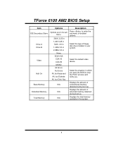
... during boot up . Displays the amount of detailed options. Displays the total memory available in the system. 8 TForce 6100 AM2 BIOS Setup Item IDE Secondary Slave Drive A Drive B Video Halt On Base Memory Extended Memory Total Memory Options Options are in its sub menu. 360K, 5.25 in 1.2M, 5.25 in 720K, 3.5 in 1.44M, 3.5 in 2.88M, 3.5 in None... Diskette All, but Disk/ Key N/A N/A N/A Description Press to stop the POST process and notify you want the BIOS to enter the sub menu of extended memory detected during boot up .
... during boot up . Displays the amount of detailed options. Displays the total memory available in the system. 8 TForce 6100 AM2 BIOS Setup Item IDE Secondary Slave Drive A Drive B Video Halt On Base Memory Extended Memory Total Memory Options Options are in its sub menu. 360K, 5.25 in 1.2M, 5.25 in 720K, 3.5 in 1.44M, 3.5 in 2.88M, 3.5 in None... Diskette All, but Disk/ Key N/A N/A N/A Description Press to stop the POST process and notify you want the BIOS to enter the sub menu of extended memory detected during boot up .
Setup Manual
Page 78
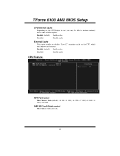
Enabled (default) Enable cache. CPU Feature NPT Fid Control The Choices: Auto (default), x4 800, x5 1000, x6 1200, x7 1400, x8 1600, x9 1800, x10 2000. Disabled Disable cache. Disabled Disable cache. External Cache This option enables or disables "Level 2" secondary cache on the CPU/chipset in use, you may improve performance. AMD K8 Cool&Quiet control The Choices: Auto (default). 12 Enabled (default) Enable cache. TForce 6100 AM2 BIOS Setup CPU Internal Cache Depending on the CPU, which may be able to increase memory access time with this option.
Enabled (default) Enable cache. CPU Feature NPT Fid Control The Choices: Auto (default), x4 800, x5 1000, x6 1200, x7 1400, x8 1600, x9 1800, x10 2000. Disabled Disable cache. Disabled Disable cache. External Cache This option enables or disables "Level 2" secondary cache on the CPU/chipset in use, you may improve performance. AMD K8 Cool&Quiet control The Choices: Auto (default). 12 Enabled (default) Enable cache. TForce 6100 AM2 BIOS Setup CPU Internal Cache Depending on the CPU, which may be able to increase memory access time with this option.
Setup Manual
Page 80
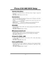
Select version supported by the operation system running on this computer. This will enable only individuals with memory exceeding 64MB. OS Select For DRAM > 64MB A choice other than Non-OS2 is held down before it begins to access the Setup Utility only. ... Disabled 14 APIC MODE Selecting Enabled enables APIC device mode reporting from the Setup main menu. Enabled (default) "Small Logo" shows when system boots up. TForce 6100 AM2 BIOS Setup Typematic Delay (Msec) Sets the delay time after the key is only used for the system to boot and is required to repeat...
Select version supported by the operation system running on this computer. This will enable only individuals with memory exceeding 64MB. OS Select For DRAM > 64MB A choice other than Non-OS2 is held down before it begins to access the Setup Utility only. ... Disabled 14 APIC MODE Selecting Enabled enables APIC device mode reporting from the Setup main menu. Enabled (default) "Small Logo" shows when system boots up. TForce 6100 AM2 BIOS Setup Typematic Delay (Msec) Sets the delay time after the key is only used for the system to boot and is required to repeat...
Setup Manual
Page 82
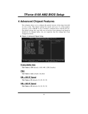
...: 4X (default).1X, 2X, 3X, 5X. TForce 6100 AM2 BIOS Setup 4 Advanced Chipset Features This submenu allows you are suspicious that came with the PCI bus. Figure 4. NB PMU The Choices: Auto (default), Disabled. The default settings that the settings have been changed unless you to system memory resources, such as DRAM. It also...
...: 4X (default).1X, 2X, 3X, 5X. TForce 6100 AM2 BIOS Setup 4 Advanced Chipset Features This submenu allows you are suspicious that came with the PCI bus. Figure 4. NB PMU The Choices: Auto (default), Disabled. The default settings that the settings have been changed unless you to system memory resources, such as DRAM. It also...
Setup Manual
Page 84
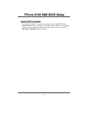
TForce 6100 AM2 BIOS Setup System BIOS Cacheable Selecting the "Disabled " option allows caching of memory will cause conflicts and result in system errors. However, any programs writing to this area of the system BIOS ROM at F0000h-FFFFFh which can improve system performance. The Choices: Disabled (default), Enabled. 18
TForce 6100 AM2 BIOS Setup System BIOS Cacheable Selecting the "Disabled " option allows caching of memory will cause conflicts and result in system errors. However, any programs writing to this area of the system BIOS ROM at F0000h-FFFFFh which can improve system performance. The Choices: Disabled (default), Enabled. 18
Setup Manual
Page 89
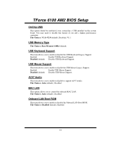
... the Onboard LAN Boot ROM. TForce 6100 AM2 BIOS Setup OnChip USB This option should be enabled if your system has a USB installed on the system board. Enabled Enable USB Keyboard Support. The Choices: Auto (default), Disabled. The Choices: V1.1+V2.0 (default), Disabled, V1.1 USB Memory Type The Choices: Base Memory(default). Disabled (default) Disable...
... the Onboard LAN Boot ROM. TForce 6100 AM2 BIOS Setup OnChip USB This option should be enabled if your system has a USB installed on the system board. Enabled Enable USB Keyboard Support. The Choices: Auto (default), Disabled. The Choices: V1.1+V2.0 (default), Disabled, V1.1 USB Memory Type The Choices: Base Memory(default). Disabled (default) Disable...
Setup Manual
Page 95
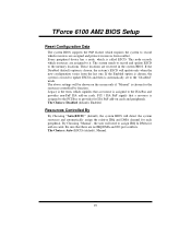
... Bus or provides for add-on cards and peripherals. The system needs to record and update ESCD to the memory locations. Be sure that a resource is automatically set to the "Disabled" mode. TForce 6100 AM2 BIOS Setup Reset Configuration Data The system BIOS supports the PnP feature which requires the system to record which...
... Bus or provides for add-on cards and peripherals. The system needs to record and update ESCD to the memory locations. Be sure that a resource is automatically set to the "Disabled" mode. TForce 6100 AM2 BIOS Setup Reset Configuration Data The system BIOS supports the PnP feature which requires the system to record which...
Setup Manual
Page 101
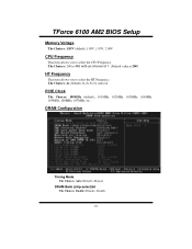
PCIE Clock The Choices: 100MHz (default), 101MHz, 102MHz, 103MHz, 104MHz, 105MHz, 106MHz, 107MHz, etc. DRAM Configuration Timing Mode The Choices: Auto (Default), Manual. DRAM Bank (chip-select)Int The Choices: Enable (Default), Disable. 35 The Choices: 4x (default),1x,2x,3x,5x.Auto,x4. The Choices: 200 to 450 with an interval of 1. (Default value is 200) HT Frequency This item allows you to select the HT Frequency. TForce 6100 AM2 BIOS Setup Memory Voltage The Choices: 1.85V (default).1.90V, 1.95V, 2.00V CPU Frequency This item allows you to select the CPU Frequency.
PCIE Clock The Choices: 100MHz (default), 101MHz, 102MHz, 103MHz, 104MHz, 105MHz, 106MHz, 107MHz, etc. DRAM Configuration Timing Mode The Choices: Auto (Default), Manual. DRAM Bank (chip-select)Int The Choices: Enable (Default), Disable. 35 The Choices: 4x (default),1x,2x,3x,5x.Auto,x4. The Choices: 200 to 450 with an interval of 1. (Default value is 200) HT Frequency This item allows you to select the HT Frequency. TForce 6100 AM2 BIOS Setup Memory Voltage The Choices: 1.85V (default).1.90V, 1.95V, 2.00V CPU Frequency This item allows you to select the CPU Frequency.
Setup Manual
Page 102
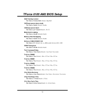
.... (Trc) Row Cycle Time The Choices: 26 bus Clocks(Default), 11~26 bus Clocks.. 36 Memory Hole Remapping The Choices: Enable (Default), Disable. Trfc0 for DIMM2 The Choices: 75ns (Default), 105ns, 127.5ns, 195ns, 327.5ns. TForce 6100 AM2 BIOS Setup DQS Training Control The Choices: Perform DQS (Default), Skip DQS CKE base power...
.... (Trc) Row Cycle Time The Choices: 26 bus Clocks(Default), 11~26 bus Clocks.. 36 Memory Hole Remapping The Choices: Enable (Default), Disable. Trfc0 for DIMM2 The Choices: 75ns (Default), 105ns, 127.5ns, 195ns, 327.5ns. TForce 6100 AM2 BIOS Setup DQS Training Control The Choices: Perform DQS (Default), Skip DQS CKE base power...


