Setup Manual
Page 2
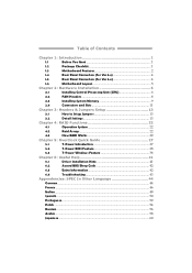
Table of Contents Chapter 1: Introduction 1 1.1 Before You Start 1 1.2 Package Checklist 1 1.3 Motherboard Features 2 1.4 Rear Panel Connectors (for Ver 5.x 4 1.5 Rear Panel Connectors (for Ver 6.x 4 1.6 Motherboard Layout 5 Chapter 2: Hardware Installation 6 2.1 Installing Central Processing Unit (CPU 6 2.2 FAN Headers 8 2.3 Installing System Memory 9 2.4 Connectors and Slots 11 Chapter 3: Headers & Jumpers Setup 13 3.1 How to ...
Table of Contents Chapter 1: Introduction 1 1.1 Before You Start 1 1.2 Package Checklist 1 1.3 Motherboard Features 2 1.4 Rear Panel Connectors (for Ver 5.x 4 1.5 Rear Panel Connectors (for Ver 6.x 4 1.6 Motherboard Layout 5 Chapter 2: Hardware Installation 6 2.1 Installing Central Processing Unit (CPU 6 2.2 FAN Headers 8 2.3 Installing System Memory 9 2.4 Connectors and Slots 11 Chapter 3: Headers & Jumpers Setup 13 3.1 How to ...
Setup Manual
Page 3
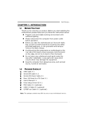
CHAPTER 1: INTRODUCTION TA770 A2+ 1.1 BEFORE YOU START Thank you take the motherboard out from dangerous area, such as heat source, humid air and water. 1.2 PACKAGE CHECKLIST HDD Cable X 1 Serial ATA Cable X 2 Serial ATA Power Cable X 1 Rear I/O Panel ... strap to bend or flex the board. „ Do not leave any unfastened small parts inside the case after installation. Before you start installing the motherboard, please make sure you follow the instructions below: „ Prepare a dry and stable working environment with sufficient lighting. „ Always disconnect the computer from power...
CHAPTER 1: INTRODUCTION TA770 A2+ 1.1 BEFORE YOU START Thank you take the motherboard out from dangerous area, such as heat source, humid air and water. 1.2 PACKAGE CHECKLIST HDD Cable X 1 Serial ATA Cable X 2 Serial ATA Power Cable X 1 Rear I/O Panel ... strap to bend or flex the board. „ Do not leave any unfastened small parts inside the case after installation. Before you start installing the motherboard, please make sure you follow the instructions below: „ Prepare a dry and stable working environment with sufficient lighting. „ Always disconnect the computer from power...
Setup Manual
Page 4
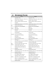
SATA Version 2.0 specification compliant. I /O functionality. Motherboard Manual 1.3 MOTHERBOARD FEATURES Ver 5.x Ver 6.x Socket AM2 / AM2+ Socket AM2 / AM2+ AMD Athlon 64 / Athlon 64 FX / Athlon 64 X2 / AMD Athlon 64 / Athlon 64 FX / Athlon ...
SATA Version 2.0 specification compliant. I /O functionality. Motherboard Manual 1.3 MOTHERBOARD FEATURES Ver 5.x Ver 6.x Socket AM2 / AM2+ Socket AM2 / AM2+ AMD Athlon 64 / Athlon 64 FX / Athlon 64 X2 / AMD Athlon 64 / Athlon 64 FX / Athlon ...
Setup Manual
Page 6
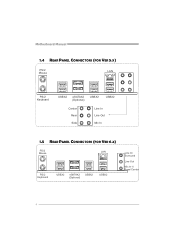
Motherboard Manual 1.4 REAR PANEL CONNECTORS (FOR VER 5.X) PS/2 Mouse LAN PS/2 Keyboard USBX2 eSATAX2 (Optional) USBX2 USBX2 Center Rear Side Line In Line Out Mic In 1.5 REAR PANEL CONNECTORS (FOR VER 6.X) PS/2 Mouse LA N PS/ 2 Ke ybo ar d USB X2 eSATAX2 (Op ti on al) USBX2 USBX2 Line In/ Surround Line Out Mic I n 1/ Bass/ Center 4
Motherboard Manual 1.4 REAR PANEL CONNECTORS (FOR VER 5.X) PS/2 Mouse LAN PS/2 Keyboard USBX2 eSATAX2 (Optional) USBX2 USBX2 Center Rear Side Line In Line Out Mic In 1.5 REAR PANEL CONNECTORS (FOR VER 6.X) PS/2 Mouse LA N PS/ 2 Ke ybo ar d USB X2 eSATAX2 (Op ti on al) USBX2 USBX2 Line In/ Surround Line Out Mic I n 1/ Bass/ Center 4
Setup Manual
Page 7
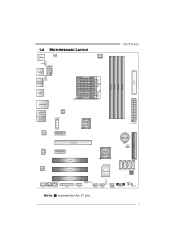
1.6 MOTHERBOARD LAYOUT JKBMS1 J KBV1 JUSBV2 J ATXPWR2 JUSB2 J USBV1 ESATAX1 (optional) JUSB1 JCFAN1 DIMMA1 DIMMB1 DIMMA2 DIMMB2 FDD1 TA770 A2+ Socket A M2 JUS BLAN1 AUDIO1 (Ver 5.x) JA UDIO1 (Ver 6.x) JSFAN2 JATXPWR3 LAN PCI_EX1_1 AMD 770 (Opt ional) eSATA PCI_EX16 PCI_EX1_2 PCI1 AMD SB600 J ATXPWR1 BAT1 JCMOS1 IDE1 Codec PCI2 JSP DI F_OUT1 JAUDIOF1 JCDIN1 PCI3 JPRNT1 JCOM1 Super I/O SATA4 SATA3 SATA2 SATA1 BIOS LED_D2 LED_D1 JUSBV3 JUSB3 JUSB4 J SFAN1 JPANEL1 RSTSW1 PWRSW1 Note: ■ represents the 1st pin. 5
1.6 MOTHERBOARD LAYOUT JKBMS1 J KBV1 JUSBV2 J ATXPWR2 JUSB2 J USBV1 ESATAX1 (optional) JUSB1 JCFAN1 DIMMA1 DIMMB1 DIMMA2 DIMMB2 FDD1 TA770 A2+ Socket A M2 JUS BLAN1 AUDIO1 (Ver 5.x) JA UDIO1 (Ver 6.x) JSFAN2 JATXPWR3 LAN PCI_EX1_1 AMD 770 (Opt ional) eSATA PCI_EX16 PCI_EX1_2 PCI1 AMD SB600 J ATXPWR1 BAT1 JCMOS1 IDE1 Codec PCI2 JSP DI F_OUT1 JAUDIOF1 JCDIN1 PCI3 JPRNT1 JCOM1 Super I/O SATA4 SATA3 SATA2 SATA1 BIOS LED_D2 LED_D1 JUSBV3 JUSB3 JUSB4 J SFAN1 JPANEL1 RSTSW1 PWRSW1 Note: ■ represents the 1st pin. 5
Setup Manual
Page 8
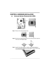
Step 3: Look for the white triangle on socket, and the gold triangle on CPU should point towards this white triangle. The CPU will fit only in the correct orientation. 6 Step 2: Pull the lever toward direction A from the socket and then raise the lever up to a 90-degree angle. Motherboard Manual CHAPTER 2: HARDWARE INSTALLATION 2.1 INSTALLING CENTRAL PROCESSING UNIT (CPU) Step 1: Remove the socket protection cap.
Step 3: Look for the white triangle on socket, and the gold triangle on CPU should point towards this white triangle. The CPU will fit only in the correct orientation. 6 Step 2: Pull the lever toward direction A from the socket and then raise the lever up to a 90-degree angle. Motherboard Manual CHAPTER 2: HARDWARE INSTALLATION 2.1 INSTALLING CENTRAL PROCESSING UNIT (CPU) Step 1: Remove the socket protection cap.
Setup Manual
Page 10
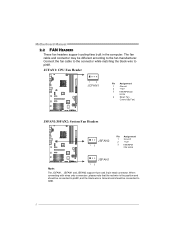
... the red wire is the positive and should be connected to pin#2, and the black wire is Ground and should be different according to pin#1. Motherboard Manual 2.2 FAN HEADERS These fan headers support cooling-fans built in the computer. JCFAN1: CPU Fan Header 1 4 JCFAN1 Pin Assignment 1 Ground 2 +12V 3 FAN RPM rate...
... the red wire is the positive and should be connected to pin#2, and the black wire is Ground and should be different according to pin#1. Motherboard Manual 2.2 FAN HEADERS These fan headers support cooling-fans built in the computer. JCFAN1: CPU Fan Header 1 4 JCFAN1 Pin Assignment 1 Ground 2 +12V 3 FAN RPM rate...
Setup Manual
Page 12
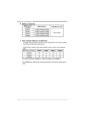
... O O O O (O means memory installed, X means memory not installed.) The DRAM bus width of the memory module must meet the following requirements: Install memory module of the motherboard, the memory module must be the same (x8 or x16) 10...
... O O O O (O means memory installed, X means memory not installed.) The DRAM bus width of the memory module must meet the following requirements: Install memory module of the motherboard, the memory module must be the same (x8 or x16) 10...
Setup Manual
Page 13
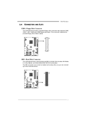
The IDE connector can connect a master and a slave drive, so you can connect up to two hard disk drives. 40 39 2 1 11 2.4 CONNECTORS AND SLOTS TA770 A2+ FDD1: Floppy Disk Connector The motherboard provides a standard floppy disk connector that provides PIO Mode 0~4, Bus Master, and Ultra DMA 33/66/100/133 functionality. This connector supports the provided floppy drive ribbon cables. 34 33 21 IDE1: Hard Disk Connector The motherboard has a 32-bit Enhanced IDE Controller that supports 360K, 720K, 1.2M, 1.44M and 2.88M floppy disk types.
The IDE connector can connect a master and a slave drive, so you can connect up to two hard disk drives. 40 39 2 1 11 2.4 CONNECTORS AND SLOTS TA770 A2+ FDD1: Floppy Disk Connector The motherboard provides a standard floppy disk connector that provides PIO Mode 0~4, Bus Master, and Ultra DMA 33/66/100/133 functionality. This connector supports the provided floppy drive ribbon cables. 34 33 21 IDE1: Hard Disk Connector The motherboard has a 32-bit Enhanced IDE Controller that supports 360K, 720K, 1.2M, 1.44M and 2.88M floppy disk types.
Setup Manual
Page 14
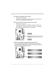
... data pins. - 2X bandwidth over the PCI-Express 1.0 architecture. This PCI slot is equipped with 3 standard PCI slots. PCI_EX1_1/PCI_EX1_2: PCI-Express Gen2 x1 Slots - Motherboard Manual PCI_EX16: PCI-Express Gen2 x16 Slot - PCI1 PCI2 PCI3 12 PCI-Express 2.0 compliant. - PCI_EX1_ 1 PCI_E X16 PCI_EX1_ 2 PCI1~PCI3: Peripheral Component Interconnect Slots This...
... data pins. - 2X bandwidth over the PCI-Express 1.0 architecture. This PCI slot is equipped with 3 standard PCI slots. PCI_EX1_1/PCI_EX1_2: PCI-Express Gen2 x1 Slots - Motherboard Manual PCI_EX16: PCI-Express Gen2 x16 Slot - PCI1 PCI2 PCI3 12 PCI-Express 2.0 compliant. - PCI_EX1_ 1 PCI_E X16 PCI_EX1_ 2 PCI1~PCI3: Peripheral Component Interconnect Slots This...
Setup Manual
Page 16
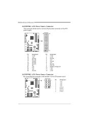
Motherboard Manual JATXPWR1: ATX Power Source Connector This connector allows user to connect 24-pin power connector on the ATX power supply. 12 24 1 13 Pin ...
Motherboard Manual JATXPWR1: ATX Power Source Connector This connector allows user to connect 24-pin power connector on the ATX power supply. 12 24 1 13 Pin ...
Setup Manual
Page 18
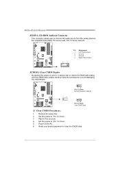
...2. Power on pin2-3, it allows user to restore the BIOS safe setting and the CMOS data, please carefully follow the procedures to avoid damaging the motherboard. 13 Pin 1-2 Close: Normal Operation (default). 13 13 Pin 2-3 Close: Clear CMOS data. ※ Clear CMOS Procedures: 1. Set the jumper to ..."Pin 2-3 close ". 5. Motherboard Manual JCDIN1: CD-ROM Audio-in Connector This connector allows user to connect the audio source from the variaty devices, like CD-ROM, DVD-ROM, ...
...2. Power on pin2-3, it allows user to restore the BIOS safe setting and the CMOS data, please carefully follow the procedures to avoid damaging the motherboard. 13 Pin 1-2 Close: Normal Operation (default). 13 13 Pin 2-3 Close: Clear CMOS data. ※ Clear CMOS Procedures: 1. Set the jumper to ..."Pin 2-3 close ". 5. Motherboard Manual JCDIN1: CD-ROM Audio-in Connector This connector allows user to connect the audio source from the variaty devices, like CD-ROM, DVD-ROM, ...
Setup Manual
Page 20
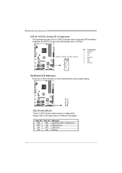
LED_D2 LED_D1 LED_D1 and LED_D2: These 2 LED indicate system power on the motherboard to show system status. Motherboard Manual SATA1~SATA4: Serial ATA Connectors The motherboard has a PCI to the table below for different messages: LED_D2 OFF OFF ON ON LED_D1 OFF ON OFF ON Message Abnormal: CPU / Chipset error. Please ...
LED_D2 LED_D1 LED_D1 and LED_D2: These 2 LED indicate system power on the motherboard to show system status. Motherboard Manual SATA1~SATA4: Serial ATA Connectors The motherboard has a PCI to the table below for different messages: LED_D2 OFF OFF ON ON LED_D1 OFF ON OFF ON Message Abnormal: CPU / Chipset error. Please ...
Setup Manual
Page 22
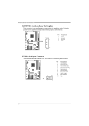
Pin Assignment 1 +12V 2 Ground 1 3 Ground 4 VCC 4 JCOM1: Serial port Connector The motherboard has a Serial Port Connector for the graphics card provides better graphics performance. Exclusive power for connecting RS-232 Port. Pin Assignment 1 Carrier detect 2 Received data 3 Transmitted data 4 Data terminal ready 5 Signal ground 6 Data set ready 7 Request to send 8 Clear to send 2 10 9 Ring indicator 10 Key 1 9 20 Motherboard Manual JATXPWR3: Auxiliary Power for Graphics This connector is an auxiliary power connection for graphics cards.
Pin Assignment 1 +12V 2 Ground 1 3 Ground 4 VCC 4 JCOM1: Serial port Connector The motherboard has a Serial Port Connector for the graphics card provides better graphics performance. Exclusive power for connecting RS-232 Port. Pin Assignment 1 Carrier detect 2 Received data 3 Transmitted data 4 Data terminal ready 5 Signal ground 6 Data set ready 7 Request to send 8 Clear to send 2 10 9 Ring indicator 10 Key 1 9 20 Motherboard Manual JATXPWR3: Auxiliary Power for Graphics This connector is an auxiliary power connection for graphics cards.
Setup Manual
Page 24
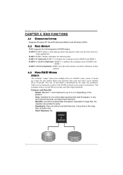
... creation of disk capacity. 4.3 HOW RAID WORKS RAID 0: The controller "stripes" data across multiple drives in the array fails, all data is up to 6 or 8. Motherboard Manual CHAPTER 4: RAID FUNCTIONS 4.1 OPERATION SYSTEM Supports Windows XP Home/Professional Edition and Windows VISTA. 4.2 RAID ARRAYS RAID supports the following types of RAID arrays...
... creation of disk capacity. 4.3 HOW RAID WORKS RAID 0: The controller "stripes" data across multiple drives in the array fails, all data is up to 6 or 8. Motherboard Manual CHAPTER 4: RAID FUNCTIONS 4.1 OPERATION SYSTEM Supports Windows XP Home/Professional Edition and Windows VISTA. 4.2 RAID ARRAYS RAID supports the following types of RAID arrays...
Setup Manual
Page 26
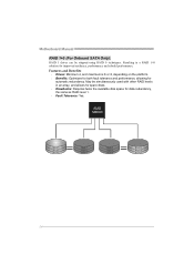
... for data redundancy, the same as RAID level 1. Fault Tolerance: Yes. Block 1 Block 3 Block 5 Block 1 Block 3 Block 5 Block 2 Block 4 Block 6 Block 2 Block 4 Block 6 24 Motherboard Manual RAID 1+0 (For Onboard SATA Only): RAID 1 drives can be simultaneously used with other RAID levels in a RAID 1+0 solution for improved resiliency, performance and rebuild...
... for data redundancy, the same as RAID level 1. Fault Tolerance: Yes. Block 1 Block 3 Block 5 Block 1 Block 3 Block 5 Block 2 Block 4 Block 6 Block 2 Block 4 Block 6 24 Motherboard Manual RAID 1+0 (For Onboard SATA Only): RAID 1 drives can be simultaneously used with other RAID levels in a RAID 1+0 solution for improved resiliency, performance and rebuild...
Setup Manual
Page 28
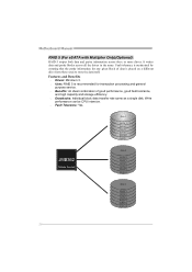
Write performance can be CPU intensive. Fault Tolerance: Yes. Motherboard Manual RAID 5 (For eSATA with Multiplier Only)(Optional): RAID 5 stripes both data and parity information across all the drives in the array. It writes data ...
Write performance can be CPU intensive. Fault Tolerance: Yes. Motherboard Manual RAID 5 (For eSATA with Multiplier Only)(Optional): RAID 5 stripes both data and parity information across all the drives in the array. It writes data ...
Setup Manual
Page 30
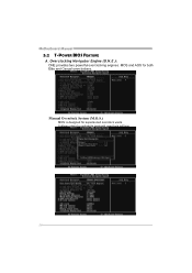
Overclocking Navigator Engine (O.N.E.): ONE provides two powerful overclocking engines: MOS and AOS for experienced overclock users. Motherboard Manual 5.2 T-POWER BIOS FEATURE A. It allows users to customize personal overclock settings. 28 Manual Overclock System (M.O.S.) MOS is designed for both Elite and Casual overclockers.
Overclocking Navigator Engine (O.N.E.): ONE provides two powerful overclocking engines: MOS and AOS for experienced overclock users. Motherboard Manual 5.2 T-POWER BIOS FEATURE A. It allows users to customize personal overclock settings. 28 Manual Overclock System (M.O.S.) MOS is designed for both Elite and Casual overclockers.
Setup Manual
Page 32
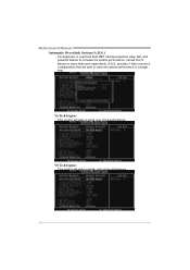
V6 Tech Engine: This engine will make a good over -clock performance. 30 V8 Tech Engine: This engine will make a better over -clock performance. provides 3 ideal overclock configurations that are able to raise the system performance in overclock field, BET had developed an easy, fast, and powerful feature to increase the system performance, named A.O.S. Motherboard Manual Automatic Overclock System (A.O.S.) For beginners in a single step. Based on many tests and experiments, A.O.S.
V6 Tech Engine: This engine will make a good over -clock performance. 30 V8 Tech Engine: This engine will make a better over -clock performance. provides 3 ideal overclock configurations that are able to raise the system performance in overclock field, BET had developed an easy, fast, and powerful feature to increase the system performance, named A.O.S. Motherboard Manual Automatic Overclock System (A.O.S.) For beginners in a single step. Based on many tests and experiments, A.O.S.
Setup Manual
Page 34
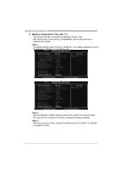
... is done, change the setting back from CMOS setup and reboot the system to test memory compatibilities, and no extra devices or software are needed. Motherboard Manual C. Step 3: When the process is "Disabled"; MIT allows users to activate this test. ↓ Step 2: Save and Exit from "Enable" to "Disable" to ensure...
... is done, change the setting back from CMOS setup and reboot the system to test memory compatibilities, and no extra devices or software are needed. Motherboard Manual C. Step 3: When the process is "Disabled"; MIT allows users to activate this test. ↓ Step 2: Save and Exit from "Enable" to "Disable" to ensure...


