
P4VMA-M user's manual
Page 8
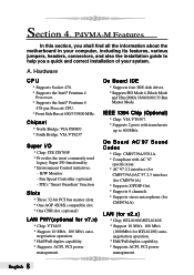
... Sound Codec * Chip: CMI9739A/9761A. * Compliant with transferrate up to help you a quick and correct installation of your system. P4VMA-M Features In this section, you shall find all the information about the motherboard in your computer, including its features, various jumpers, headers, connectors, and also the installation guide to 400Mb/s. Fan Speed...
... Sound Codec * Chip: CMI9739A/9761A. * Compliant with transferrate up to help you a quick and correct installation of your system. P4VMA-M Features In this section, you shall find all the information about the motherboard in your computer, including its features, various jumpers, headers, connectors, and also the installation guide to 400Mb/s. Fan Speed...
P4VMA-M user's manual
Page 11
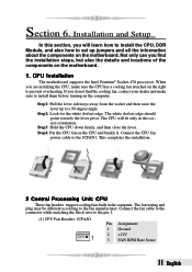
.... This completes the installation. 2 Central Processing Unit: CPU These fan headers support cooling fans built in the correct orientation. CPU Installation The motherboard supports the Intel Pentium® Socket-478 processor. Section 6. Connect the fan cable to the connector while matching the black wire to set ... to the fan manufacturer. If you find the cooling fan, contact your dealer and make sure the CPU has a cooling fan attached on the motherboard. 1. The white dot/cut edge. The CPU will learn how to install the CPU, DDR Module, and also how to the pin 1. ...
.... This completes the installation. 2 Central Processing Unit: CPU These fan headers support cooling fans built in the correct orientation. CPU Installation The motherboard supports the Intel Pentium® Socket-478 processor. Section 6. Connect the fan cable to the connector while matching the black wire to set ... to the fan manufacturer. If you find the cooling fan, contact your dealer and make sure the CPU has a cooling fan attached on the motherboard. 1. The white dot/cut edge. The CPU will learn how to install the CPU, DDR Module, and also how to the pin 1. ...
P4VMA-M user's manual
Page 12
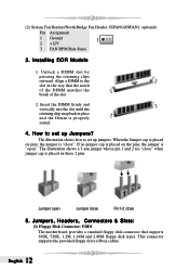
Jumpers, Headers, Connectors & Slots: (1) Floppy Disk Connector: FDD1 The motherboard provides a standard floppy disk connector that the notch of the DIMM matches the break of the slot. 2. The illustration shows how to set up jumpers. ...
Jumpers, Headers, Connectors & Slots: (1) Floppy Disk Connector: FDD1 The motherboard provides a standard floppy disk connector that the notch of the DIMM matches the break of the slot. 2. The illustration shows how to set up jumpers. ...
P4VMA-M user's manual
Page 13
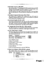
.... (7) Wake On LAN Header: JWOL1/JWOM1 ( optional) This connector allows you to connect to IDE1. (3) Peripheral Component Interconnect Slots: PCI1-3 This motherboard is designed as 32 bits. (4) Accelerated Graphics Port Slot: AGP1 Your monitor will take advantage of date, time, and system setup parameters. The first...also equipped with Wake On LAN function. The IDE connectors can wake up to clear the Real Time Clock (RTC) Ram in CMOS. This motherboard supports video cards for five seconds. 4. You can connect a master and a slave drive, so you to four hard disk drives. It ...
.... (7) Wake On LAN Header: JWOL1/JWOM1 ( optional) This connector allows you to connect to IDE1. (3) Peripheral Component Interconnect Slots: PCI1-3 This motherboard is designed as 32 bits. (4) Accelerated Graphics Port Slot: AGP1 Your monitor will take advantage of date, time, and system setup parameters. The first...also equipped with Wake On LAN function. The IDE connectors can wake up to clear the Real Time Clock (RTC) Ram in CMOS. This motherboard supports video cards for five seconds. 4. You can connect a master and a slave drive, so you to four hard disk drives. It ...
P4VMA-M user's manual
Page 14
...USB devices function," " JUSBV1/JUSBV2/ JUSBV3" jumper cap should be placed on pin 2-3 respectively. (10) Serial ATA Connector: JSATA1/JSATA2 The motherboard has a PCI to a maximum throughput of 480 Mbps, which is 40 times faster than USB 1.1, and is ideal for connecting high-speed USB... with 1.5GHz speed. JUSBV3: 5V Standby voltage for USB at the JUSB3/JUSB4 port connectors. (8) Front USB Header: JUSB3/ JUSB4 The motherboard provides two USB 2.0 Pin Header. JUSBV2: 5V Standby voltage for USB at the JUSBLAN1 port connector. JUSBV2: 5V for USB at the JUSBLAN1port...
...USB devices function," " JUSBV1/JUSBV2/ JUSBV3" jumper cap should be placed on pin 2-3 respectively. (10) Serial ATA Connector: JSATA1/JSATA2 The motherboard has a PCI to a maximum throughput of 480 Mbps, which is 40 times faster than USB 1.1, and is ideal for connecting high-speed USB... with 1.5GHz speed. JUSBV3: 5V Standby voltage for USB at the JUSB3/JUSB4 port connectors. (8) Front USB Header: JUSB3/ JUSB4 The motherboard provides two USB 2.0 Pin Header. JUSBV2: 5V Standby voltage for USB at the JUSBLAN1 port connector. JUSBV2: 5V for USB at the JUSBLAN1port...
P4VMA-M user's manual
Page 16
... for the power system. Before installing the power supply connector, please make sure that all components are installed properly. (14) Power Connector: JATXPWR1/JATXPWR2 The motherboard supports ATX power supply for digital audio transmission.
... for the power system. Before installing the power supply connector, please make sure that all components are installed properly. (14) Power Connector: JATXPWR1/JATXPWR2 The motherboard supports ATX power supply for digital audio transmission.
P4VMA-M user's manual
Page 26
..., [ WarpSpeederTM ] utility will display a little tray icon on hand. [WarpSpeederTM] includes 1 tray icon and 5 panels: 1. b. You can right-click the little tray icon to your motherboard on the right side of Windows Taskbar. The "Launch Utility" item in the popup menu has the same function as mouse left button in this...
..., [ WarpSpeederTM ] utility will display a little tray icon on hand. [WarpSpeederTM] includes 1 tray icon and 5 panels: 1. b. You can right-click the little tray icon to your motherboard on the right side of Windows Taskbar. The "Launch Utility" item in the popup menu has the same function as mouse left button in this...
P4VMA-M BIOS setup guide
Page 18
... PIO 17 If the interface does not support prefetching. 5 Integrated Peripherals Figure 5. IDE DMA Transfer Access The Choices: Enabled (default), Disabled. OnChip IDE Channel 0/1 The motherboard chipset contains a PCI IDE interface with the following options: OnChip SATA This option allows you a submenu with support for faster drive access. Select "Enabled" to...
... PIO 17 If the interface does not support prefetching. 5 Integrated Peripherals Figure 5. IDE DMA Transfer Access The Choices: Enabled (default), Disabled. OnChip IDE Channel 0/1 The motherboard chipset contains a PCI IDE interface with the following options: OnChip SATA This option allows you a submenu with support for faster drive access. Select "Enabled" to...
P4VMA-M BIOS setup guide
Page 24
...is lost when system is not live , then after S3 . Delay Prior to enter the Soft-Off state when the system has "hung." the motherboard battery (3V), the Power Supply (5VSB), and the Power Supply (3.3V). When the Power Supply is lost "Former-Sts" Means to initialize ...sources that retains these Power-On instructions; "On" Means always set CMOS to the video buffer. The system time is not supplying power, the motherboard uses the motherboard battery (3V). The Choices: Auto (default), Yes, No. While AC is shortened if you disable the function , but system will remain powered...
...is lost when system is not live , then after S3 . Delay Prior to enter the Soft-Off state when the system has "hung." the motherboard battery (3V), the Power Supply (5VSB), and the Power Supply (3.3V). When the Power Supply is lost "Former-Sts" Means to initialize ...sources that retains these Power-On instructions; "On" Means always set CMOS to the video buffer. The system time is not supplying power, the motherboard uses the motherboard battery (3V). The Choices: Auto (default), Yes, No. While AC is shortened if you disable the function , but system will remain powered...

