
M7VIG 400 user's manual
Page 4
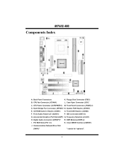
North Bridge Fan Connector (JNFAN1)* N. Front Audio Header (JF_AUDIO1) P. Accelerated Graphics Port Slot (AGP1) Q. Clear CMOS Function (JCMOS1) J. DDR Modules (DDR1-2) I. CPU Fan Connector (JCFAN1) L. CD-ROM Audio-In Header (JCDIN1) O. Frequency Selection (JCLK1) H. Digital Audio Connector (JSPDIF1)* R. Case Open Connector (JCI1)* C. System FAN Header (JSFAN1) E. IDE ...
North Bridge Fan Connector (JNFAN1)* N. Front Audio Header (JF_AUDIO1) P. Accelerated Graphics Port Slot (AGP1) Q. Clear CMOS Function (JCMOS1) J. DDR Modules (DDR1-2) I. CPU Fan Connector (JCFAN1) L. CD-ROM Audio-In Header (JCDIN1) O. Frequency Selection (JCLK1) H. Digital Audio Connector (JSPDIF1)* R. Case Open Connector (JCI1)* C. System FAN Header (JSFAN1) E. IDE ...
M7VIG 400 user's manual
Page 6
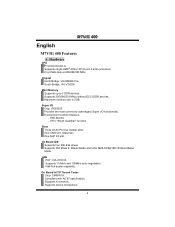
.../s and 100Mb/s auto-negotiation. Compliant with AC'97 specification. Supports 6 channels. Hardware CPU Provides Socket A. Maximum memory size is 2GB. H/W Monitor - Supports PIO Mode 4, Master Mode and Ultra DMA 33/66/100/133 Bus Master Mode. MM77VVIIGG 440000 English M7VIG 400 Features A. ITE's "Smart Guardian" function Slots Three 32-bit PCI bus master...
.../s and 100Mb/s auto-negotiation. Compliant with AC'97 specification. Supports 6 channels. Hardware CPU Provides Socket A. Maximum memory size is 2GB. H/W Monitor - Supports PIO Mode 4, Master Mode and Ultra DMA 33/66/100/133 Bus Master Mode. MM77VVIIGG 440000 English M7VIG 400 Features A. ITE's "Smart Guardian" function Slots Three 32-bit PCI bus master...
M7VIG 400 user's manual
Page 8
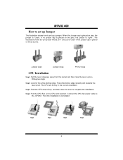
...correct orientation. Then the installation is placed on the pins, the jumper is "close CPU Installation Step1: Pull the lever sideways away from the socket and then raise the lever...towards the lever pivot. The white dot/cut edge. Step4: Put the CPU Fan on pins, the jumper is "open Jumper close Pin1-2 close ". Step1 Step2 Step3 Step4 6 Step3: ...Hold the CPU down firmly, and then close " when jumper cap is completed. Connect the CPU fan power cable to set up Jumper The illustration shows how to the ...
...correct orientation. Then the installation is placed on the pins, the jumper is "close CPU Installation Step1: Pull the lever sideways away from the socket and then raise the lever...towards the lever pivot. The white dot/cut edge. Step4: Put the CPU Fan on pins, the jumper is "open Jumper close Pin1-2 close ". Step1 Step2 Step3 Step4 6 Step3: ...Hold the CPU down firmly, and then close " when jumper cap is completed. Connect the CPU fan power cable to set up Jumper The illustration shows how to the ...
M7VIG 400 user's manual
Page 9
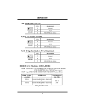
... Module Total Memory Size (MB) DDR 1 64MB/128MB/256MB/512MB/1GB *1 Max is DDR 2 64MB/128MB/256MB/512MB/1GB *1 ***Only for reference*** 2GB 7 MM77VVIIGG 440000 CPU Fan Header: JCFAN1 Pin 1 1 2 JCFAN1 3 Assignment Ground +12V FAN RPM rate Sense System Fan Header: JSFAN1 Pin 1 1 2 JSFAN1 3 Assignment Ground +12V FAN RPM rate Sense...
... Module Total Memory Size (MB) DDR 1 64MB/128MB/256MB/512MB/1GB *1 Max is DDR 2 64MB/128MB/256MB/512MB/1GB *1 ***Only for reference*** 2GB 7 MM77VVIIGG 440000 CPU Fan Header: JCFAN1 Pin 1 1 2 JCFAN1 3 Assignment Ground +12V FAN RPM rate Sense System Fan Header: JSFAN1 Pin 1 1 2 JSFAN1 3 Assignment Ground +12V FAN RPM rate Sense...
M7VIG 400 user's manual
Page 17
... computer systems if the setting is not appropriate when testing and results in the About panel, you do not need to power up CPU core voltage and Memory voltage. The Overvoltage Manager, on our main panel. System Requirement OS Support: Windows 98 SE, Windows Me, ...a new powerful control utility, features three user-friendly functions including Overclock Manager, Overvoltage Manager, and Hardware Monitor. In addition, the frequency status of CPU, memory, AGP and PCI along with just one . With the Overclock Manager, users can easily adjust the frequency they prefer or they can get...
... computer systems if the setting is not appropriate when testing and results in the About panel, you do not need to power up CPU core voltage and Memory voltage. The Overvoltage Manager, on our main panel. System Requirement OS Support: Windows 98 SE, Windows Me, ...a new powerful control utility, features three user-friendly functions including Overclock Manager, Overvoltage Manager, and Hardware Monitor. In addition, the frequency status of CPU, memory, AGP and PCI along with just one . With the Overclock Manager, users can easily adjust the frequency they prefer or they can get...
M7VIG 400 user's manual
Page 20
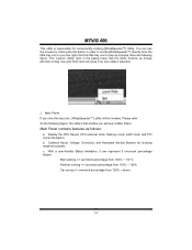
... menu has the same function as follows: a. The "Launch Utility" item in order to invoke [WarpSpeeder™] directly from 120% ~ above 18 Display the CPU Speed, CPU external clock, Memory clock, AGP clock, and PCI clock information. You can use the mouse by clicking the left -click on tray icon and "Exit...
... menu has the same function as follows: a. The "Launch Utility" item in order to invoke [WarpSpeeder™] directly from 120% ~ above 18 Display the CPU Speed, CPU external clock, Memory clock, AGP clock, and PCI clock information. You can use the mouse by clicking the left -click on tray icon and "Exit...
M7VIG 400 user's manual
Page 21
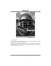
Voltage Panel Click the Voltage button in Main Panel, the button will be highlighted and the Voltage Panel will slide out to increase CPU core voltage and Memory voltage or not. MM77VVIIGG 440000 3. In this panel, you click the option "Yes". 19 The default setting is "No". If you want to get the best performance of overclocking, we recommend you can decide to up as the following figure.
Voltage Panel Click the Voltage button in Main Panel, the button will be highlighted and the Voltage Panel will slide out to increase CPU core voltage and Memory voltage or not. MM77VVIIGG 440000 3. In this panel, you click the option "Yes". 19 The default setting is "No". If you want to get the best performance of overclocking, we recommend you can decide to up as the following figure.


