
M7VIG 400 user's manual
Page 1
... These limits are trademarks of this user's manual. This equipment generates, uses and can radiate radio frequency energy and, if not installed and used in writing. Further the vendor reserves the right to revise this publication and to make changes to the contents here of without ...limits of a Class B digital device, pursuant to radio communications. The vendor makes no guarantee that interference will not be changed without first obtaining the vendor's approval in accordance with the instructions, may cause harmful interference to Part 15 of merchantability or fitness for ...
... These limits are trademarks of this user's manual. This equipment generates, uses and can radiate radio frequency energy and, if not installed and used in writing. Further the vendor reserves the right to revise this publication and to make changes to the contents here of without ...limits of a Class B digital device, pursuant to radio communications. The vendor makes no guarantee that interference will not be changed without first obtaining the vendor's approval in accordance with the instructions, may cause harmful interference to Part 15 of merchantability or fitness for ...
M7VIG 400 user's manual
Page 3
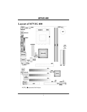
MM77VVIIGG 440000 Layout of M7VIG 400 NOTE: ●represents the first pin. 1
MM77VVIIGG 440000 Layout of M7VIG 400 NOTE: ●represents the first pin. 1
M7VIG 400 user's manual
Page 4
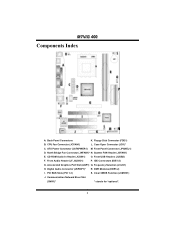
... (JF_AUDIO1) P. Clear CMOS Function (JCMOS1) J. Front Panel Connector (JPANEL1) D. Frequency Selection (JCLK1) H. Digital Audio Connector (JSPDIF1)* R. PCI BUS Slots (PCI 1-3) S. North Bridge Fan Connector (JNFAN1)* N. DDR Modules (DDR1-2) I. Case Open Connector (JCI1)* C. IDE Connectors (IDE1-2) G. Back Panel Connectors K. System FAN Header (JSFAN1) E. Accelerated Graphics Port Slot (AGP1) Q. Front USB Headers (JUSB2) F. ATX Power Connector (JATXPWER1) M. CD-ROM Audio-In Header (JCDIN1) O. Communication Network Riser Slot (CNR1)* * stands for "optional...
... (JF_AUDIO1) P. Clear CMOS Function (JCMOS1) J. Front Panel Connector (JPANEL1) D. Frequency Selection (JCLK1) H. Digital Audio Connector (JSPDIF1)* R. PCI BUS Slots (PCI 1-3) S. North Bridge Fan Connector (JNFAN1)* N. DDR Modules (DDR1-2) I. Case Open Connector (JCI1)* C. IDE Connectors (IDE1-2) G. Back Panel Connectors K. System FAN Header (JSFAN1) E. Accelerated Graphics Port Slot (AGP1) Q. Front USB Headers (JUSB2) F. ATX Power Connector (JATXPWER1) M. CD-ROM Audio-In Header (JCDIN1) O. Communication Network Riser Slot (CNR1)* * stands for "optional...
M7VIG 400 user's manual
Page 6
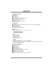
... VT8235. Maximum memory size is 2GB. Super I /O functionality. Chipset North Bridge: VIA KM266 Pro. Provides the most commonly used legacy Super I /O Chip: ITE8705F. On Board AC'97 Sound Codec Chip: CMI9761A. Compliant with AC'97 specification. Front Side Bus at 200/266/333 MHz. H/W Monitor - One CNR slot. (Optional) One AGP 4X slot. MM77VVIIGG 440000 English M7VIG 400 Features A. On Board IDE Supports four IDE disk drives. LAN PHY: VIA VT6103. Supports PIO Mode 4, Master Mode and Ultra...
... VT8235. Maximum memory size is 2GB. Super I /O functionality. Chipset North Bridge: VIA KM266 Pro. Provides the most commonly used legacy Super I /O Chip: ITE8705F. On Board AC'97 Sound Codec Chip: CMI9761A. Compliant with AC'97 specification. Front Side Bus at 200/266/333 MHz. H/W Monitor - One CNR slot. (Optional) One AGP 4X slot. MM77VVIIGG 440000 English M7VIG 400 Features A. On Board IDE Supports four IDE disk drives. LAN PHY: VIA VT6103. Supports PIO Mode 4, Master Mode and Ultra...
M7VIG 400 user's manual
Page 7
... 2 USB2.0 ports. 1 front audio header. 1 S/PDIF Out header. (optional) Dimensions Micro ATX Form Factor: 19.4 cm X 24.4 cm (W X L) B. BIOS & Software BIOS Award legal BIOS. Supports ACPI. Supports USB Function. b. Application CD X 1 (optional) USB 2.0 Cable X 1 (optional) S/PDIF Cable X 1 (optional) Rear I/O Panel for Windows 98 SE, Windows 2000, Windows Me, Windows XP, UNIX Series etc. MM77VVIIGG 440000 On Board Peripherals a. Rear side 1 serial port. 1 VGA port. 1 parallel port. (SPP/EPP/ECP mode) Audio ports in vertical position. 1 RJ-45 LAN jack. PS/2 mouse and PS/2 keyboard...
... 2 USB2.0 ports. 1 front audio header. 1 S/PDIF Out header. (optional) Dimensions Micro ATX Form Factor: 19.4 cm X 24.4 cm (W X L) B. BIOS & Software BIOS Award legal BIOS. Supports ACPI. Supports USB Function. b. Application CD X 1 (optional) USB 2.0 Cable X 1 (optional) S/PDIF Cable X 1 (optional) Rear I/O Panel for Windows 98 SE, Windows 2000, Windows Me, Windows XP, UNIX Series etc. MM77VVIIGG 440000 On Board Peripherals a. Rear side 1 serial port. 1 VGA port. 1 parallel port. (SPP/EPP/ECP mode) Audio ports in vertical position. 1 RJ-45 LAN jack. PS/2 mouse and PS/2 keyboard...
M7VIG 400 user's manual
Page 8
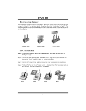
... set up to complete the installation. The illustration shows a 3-pin jumper whose pin 1 and 2 are "close" when jumper cap is "open Jumper close Pin1-2 close the lever to a 90-degree angle. Connect the CPU fan power cable to set up Jumper The illustration shows how to the JCFAN1. Step3: Hold the CPU down firmly, and then close CPU Installation Step1: Pull the lever sideways away from the socket...
... set up to complete the installation. The illustration shows a 3-pin jumper whose pin 1 and 2 are "close" when jumper cap is "open Jumper close Pin1-2 close the lever to a 90-degree angle. Connect the CPU fan power cable to set up Jumper The illustration shows how to the JCFAN1. Step3: Hold the CPU down firmly, and then close CPU Installation Step1: Pull the lever sideways away from the socket...
M7VIG 400 user's manual
Page 9
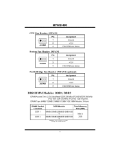
... Bridge Fan Header: JNFAN1 (optional) Pin Assignment 1 1 Ground 2 JNFAN1 3 +12V FAN RPM rate Sense DDR DIMM Modules: DDR1, DDR2 DRAM Access Time: 2.5V Unbuffered/ DDR 200 MHz (PC1600)/DDR 266 MHz (PC2100)/ DDR 333 MHz (PC2700) Type required. DRAM Type: 64MB/ 128MB/ 256MB/ 512MB/ 1GB DIMM Module (184 pin) DIMM Socket Location DDR Module Total Memory Size (MB) DDR 1 64MB/128MB/256MB/512MB/1GB *1 Max is...
... Bridge Fan Header: JNFAN1 (optional) Pin Assignment 1 1 Ground 2 JNFAN1 3 +12V FAN RPM rate Sense DDR DIMM Modules: DDR1, DDR2 DRAM Access Time: 2.5V Unbuffered/ DDR 200 MHz (PC1600)/DDR 266 MHz (PC2100)/ DDR 333 MHz (PC2700) Type required. DRAM Type: 64MB/ 128MB/ 256MB/ 512MB/ 1GB DIMM Module (184 pin) DIMM Socket Location DDR Module Total Memory Size (MB) DDR 1 64MB/128MB/256MB/512MB/1GB *1 Max is...
M7VIG 400 user's manual
Page 10
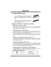
... be connected to four hard disk drives. Peripheral Component Interconnect Slots: PCI 1-3 This motherboard is properly seated. Jumpers, Headers, Connectors & Slots Floppy Disk Connector: FDD1 The motherboard provides a standard floppy disk connector that the notch of the DIMM matches the break of AGP technology for Peripheral Component Interconnect, and it defines a hardware scalable riser card interface, which supports modem only. Accelerated Graphics Port Slot: AGP1 Your monitor will take advantage of the slot. 2. Communication Network Riser Slot: CNR1 (optional...
... be connected to four hard disk drives. Peripheral Component Interconnect Slots: PCI 1-3 This motherboard is properly seated. Jumpers, Headers, Connectors & Slots Floppy Disk Connector: FDD1 The motherboard provides a standard floppy disk connector that the notch of the DIMM matches the break of AGP technology for Peripheral Component Interconnect, and it defines a hardware scalable riser card interface, which supports modem only. Accelerated Graphics Port Slot: AGP1 Your monitor will take advantage of the slot. 2. Communication Network Riser Slot: CNR1 (optional...

M7VIG 400 user's manual
Page 11
... Panel Connector: JPANEL1 Ground JPANEL1 PWR_ LED SLP ON/ OFF 2 1 SPK (+ ) (-) HLED RST IR 24 23 IR Pin Assignment 1 +5V 3 NA 5 NA 7 Speaker 9 HDD LED (+) 11 HDD LED (-) 13 Ground 15 Reset Control 17 NA 19 NA 21 +5V 23 IRTX Function Speaker Connector Hard Drive LED Reset Button IrDA Connector Pin Assignment 2 Sleep Control 4 Ground 6 NA 8 Power LED (+) 10 Power LED (+) 12 Power LED (-) 14 Power Button 16 Ground 18 KEY 20 KEY 22 Ground 24 IRRX Function Sleep Button NA POWER LED Power-on Button IrDA Connector Power Connectors...
... Panel Connector: JPANEL1 Ground JPANEL1 PWR_ LED SLP ON/ OFF 2 1 SPK (+ ) (-) HLED RST IR 24 23 IR Pin Assignment 1 +5V 3 NA 5 NA 7 Speaker 9 HDD LED (+) 11 HDD LED (-) 13 Ground 15 Reset Control 17 NA 19 NA 21 +5V 23 IRTX Function Speaker Connector Hard Drive LED Reset Button IrDA Connector Pin Assignment 2 Sleep Control 4 Ground 6 NA 8 Power LED (+) 10 Power LED (+) 12 Power LED (-) 14 Power Button 16 Ground 18 KEY 20 KEY 22 Ground 24 IRRX Function Sleep Button NA POWER LED Power-on Button IrDA Connector Power Connectors...
M7VIG 400 user's manual
Page 12
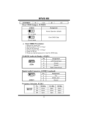
... (default) Clear CMOS Data Pin 2-3 Close ※ Clear CMOS Procedures: 1. CD-ROM Audio-In Header: JCDIN1 Pin Assignment 1 4 JCDIN1 1 Left Channel Input 2 Ground 3 Ground 4 Right Channel Input Digital Audio Connector: JSPDIF1 (optional) 1 3 Pin 1 2 JSPDIF1 3 Assignment +5V SPDIF_OUT Ground Frequency Selection: JCLK1 Pin 100 MHz 21 78 1-2 Close 3-4 Close 5-6 Open 133 MHz Open Close Open 166 MHz Open Open Open 10 Power on the AC. 6. Remove AC power line. 2. Reset your desired password or clear...
... (default) Clear CMOS Data Pin 2-3 Close ※ Clear CMOS Procedures: 1. CD-ROM Audio-In Header: JCDIN1 Pin Assignment 1 4 JCDIN1 1 Left Channel Input 2 Ground 3 Ground 4 Right Channel Input Digital Audio Connector: JSPDIF1 (optional) 1 3 Pin 1 2 JSPDIF1 3 Assignment +5V SPDIF_OUT Ground Frequency Selection: JCLK1 Pin 100 MHz 21 78 1-2 Close 3-4 Close 5-6 Open 133 MHz Open Close Open 166 MHz Open Open Open 10 Power on the AC. 6. Remove AC power line. 2. Reset your desired password or clear...
M7VIG 400 user's manual
Page 13
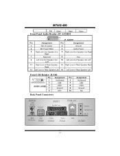
... Right Line In/ Rear Speaker Right Right 13 Left Line In/ Rear Speaker Left 14 Left Line In/ Rear Speaker Left Front USB Header: JUSB2 9 1 Pin 1 Assignment +5V(fused) Pin 2 10 23 USB- 4 JUSB1/ JUSB2 5 USB+ 6 7 Ground 8 9 KEY 10 Back Panel Connectors Assignment +5V(fused) USBUSB+ Ground NA JKBMS1 PS/2 Mouse (optional) PS/2 Keyboard USB JUSB3 JPRNT1 Parallel Port JUSBLAN1 LAN Line In Speaker Out Mic In COM1...
... Right Line In/ Rear Speaker Right Right 13 Left Line In/ Rear Speaker Left 14 Left Line In/ Rear Speaker Left Front USB Header: JUSB2 9 1 Pin 1 Assignment +5V(fused) Pin 2 10 23 USB- 4 JUSB1/ JUSB2 5 USB+ 6 7 Ground 8 9 KEY 10 Back Panel Connectors Assignment +5V(fused) USBUSB+ Ground NA JKBMS1 PS/2 Mouse (optional) PS/2 Keyboard USB JUSB3 JPRNT1 Parallel Port JUSBLAN1 LAN Line In Speaker Out Mic In COM1...
M7VIG 400 user's manual
Page 17
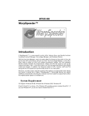
... install DirectX 8.1.) 15 If you use Windows XP, you can get detail descriptions about BIOS model and chipsets. The Overvoltage Manager, on our main panel. Moreover, to power up CPU core voltage and Memory voltage. The cool Hardware Monitor smartly indicates the temperatures, voltage and CPU fan speed as well as the chipset information. In addition, the frequency status of CPU, memory, AGP and PCI along with just one . System Requirement OS Support: Windows 98 SE, Windows Me, Windows 2000, Windows...
... install DirectX 8.1.) 15 If you use Windows XP, you can get detail descriptions about BIOS model and chipsets. The Overvoltage Manager, on our main panel. Moreover, to power up CPU core voltage and Memory voltage. The cool Hardware Monitor smartly indicates the temperatures, voltage and CPU fan speed as well as the chipset information. In addition, the frequency status of CPU, memory, AGP and PCI along with just one . System Requirement OS Support: Windows 98 SE, Windows Me, Windows 2000, Windows...
M7VIG 400 user's manual
Page 19
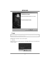
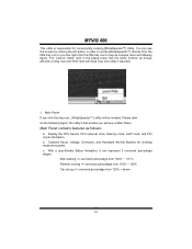
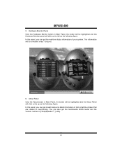
Tray Icon: Whenever the Tray Icon utility is launched, it will change according to your motherboard on the right side of Windows Taskbar. 17 MM77VVIIGG 440000 Usage The following figures are just only for reference, the screen printed in this user manual will display a little tray icon on hand. [WarpSpeeder™] includes 1 tray icon and 5 panels: 1.
Tray Icon: Whenever the Tray Icon utility is launched, it will change according to your motherboard on the right side of Windows Taskbar. 17 MM77VVIIGG 440000 Usage The following figures are just only for reference, the screen printed in this user manual will display a little tray icon on hand. [WarpSpeeder™] includes 1 tray icon and 5 panels: 1.
M7VIG 400 user's manual
Page 20
... Tray Icon utility if selected. 2. Display the CPU Speed, CPU external clock, Memory clock, AGP clock, and PCI clock information. You can right-click the little tray icon to invoke [WarpSpeeder™] directly from 120% ~ above 18 MM77VVIIGG 440000 This utility is Main Panel. Main Panel contains features as mouse left button in the popup menu has the same function as follows: a. Contains About, Voltage, Overclock, and Hardware Monitor Buttons for conveniently...
... Tray Icon utility if selected. 2. Display the CPU Speed, CPU external clock, Memory clock, AGP clock, and PCI clock information. You can right-click the little tray icon to invoke [WarpSpeeder™] directly from 120% ~ above 18 MM77VVIIGG 440000 This utility is Main Panel. Main Panel contains features as mouse left button in the popup menu has the same function as follows: a. Contains About, Voltage, Overclock, and Hardware Monitor Buttons for conveniently...
M7VIG 400 user's manual
Page 21
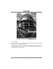
In this panel, you click the option "Yes". 19 If you want to get the best performance of overclocking, we recommend you can decide to up as the following figure. MM77VVIIGG 440000 3. Voltage Panel Click the Voltage button in Main Panel, the button will be highlighted and the Voltage Panel will slide out to increase CPU core voltage and Memory voltage or not. The default setting is "No".
In this panel, you click the option "Yes". 19 If you want to get the best performance of overclocking, we recommend you can decide to up as the following figure. MM77VVIIGG 440000 3. Voltage Panel Click the Voltage button in Main Panel, the button will be highlighted and the Voltage Panel will slide out to increase CPU core voltage and Memory voltage or not. The default setting is "No".
M7VIG 400 user's manual
Page 23
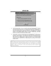
... Auto overclock button and let [ WarpSpeeder™ ] automatically gets the best result for you overclock by click the Verify button. "Recovery Dialog button": Pop up the following dialog. Warning: Manually overclock is potentially dangerous, especially when the overclocking percentage is over 110 %. Let user select a restoring way if system need to do a fail-safe reboot. 21 "-3MHz button", "-1MHz button", "+1MHz button", and "+3MHz button": provide user...
... Auto overclock button and let [ WarpSpeeder™ ] automatically gets the best result for you overclock by click the Verify button. "Recovery Dialog button": Pop up the following dialog. Warning: Manually overclock is potentially dangerous, especially when the overclocking percentage is over 110 %. Let user select a restoring way if system need to do a fail-safe reboot. 21 "-3MHz button", "-1MHz button", "+1MHz button", and "+3MHz button": provide user...
M7VIG 400 user's manual
Page 24
... Recovery Dialog's setting. MM77VVIIGG 440000 d. After reboot, the [ WarpSpeeder™ ] utility will do fail-safe reboot by using Watchdog function. Note: Because the testing programs, invoked in Auto-overclock and Verify, include DirectDraw, Direct3D and DirectShow tests, the DirectX 8.1 or newer runtime library is required for current frequency. And please make sure your display card's color depth is High color (16 bit...
... Recovery Dialog's setting. MM77VVIIGG 440000 d. After reboot, the [ WarpSpeeder™ ] utility will do fail-safe reboot by using Watchdog function. Note: Because the testing programs, invoked in Auto-overclock and Verify, include DirectDraw, Direct3D and DirectShow tests, the DirectX 8.1 or newer runtime library is required for current frequency. And please make sure your display card's color depth is High color (16 bit...
M7VIG 400 user's manual
Page 25
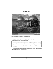
You can also get the mainboard's BIOS model and the Version number of all the chipset that are related to up as the following figure. Hardware Monitor Panel Click the Hardware Monitor button in Main Panel, the button will be refreshed every 1 second. 6. The information will be highlighted and the Hardware Monitor panel will slide out to overclocking. In this panel, you can get the real-time...
You can also get the mainboard's BIOS model and the Version number of all the chipset that are related to up as the following figure. Hardware Monitor Panel Click the Hardware Monitor button in Main Panel, the button will be refreshed every 1 second. 6. The information will be highlighted and the Hardware Monitor panel will slide out to overclocking. In this panel, you can get the real-time...
M7VIG 400 user's manual
Page 26
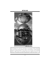
If one chipset is not on board, the correlative button in Main panel will be disabled, but will not interfere other panels' functions. This property can make [ WarpSpeeder™ ] utility more robust. 24 MM77VVIIGG 440000 Note: Because the overclock, overvoltage, and hardware monitor features are controlled by several separate chipset, [ WarpSpeeder™ ] divide these features to separate panels.
If one chipset is not on board, the correlative button in Main panel will be disabled, but will not interfere other panels' functions. This property can make [ WarpSpeeder™ ] utility more robust. 24 MM77VVIIGG 440000 Note: Because the overclock, overvoltage, and hardware monitor features are controlled by several separate chipset, [ WarpSpeeder™ ] divide these features to separate panels.
M7VIG 400 user's manual
Page 27
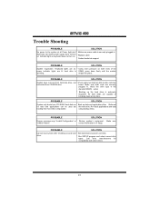
... * Back up the hard drive is in the standard CMOS setup. * Backing up data and applications files. Call drive manufacturers for compatibility with other drives. 25 Keyboard lights are on, * Using even pressure on * Replace cable * Contact technical support PROBABLE SOLUTION System inoperative. MM77VVIIGG 440000 Trouble Shooting PROBABLE SOLUTION No power to disk controller be booted from CD-ROM drive. check the drive type in setup. PROBABLE SOLUTION Screen message says "Invalid Configuration" or * Review system's equipment .
... * Back up the hard drive is in the standard CMOS setup. * Backing up data and applications files. Call drive manufacturers for compatibility with other drives. 25 Keyboard lights are on, * Using even pressure on * Replace cable * Contact technical support PROBABLE SOLUTION System inoperative. MM77VVIIGG 440000 Trouble Shooting PROBABLE SOLUTION No power to disk controller be booted from CD-ROM drive. check the drive type in setup. PROBABLE SOLUTION Screen message says "Invalid Configuration" or * Review system's equipment .


