Setup Manual
Page 2
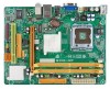
... 1: Introduction 1 1.1 Before You Start 1 1.2 Package Checklist 1 1.3 Motherboard Features 2 1.4 Rear Panel Connectors 3 1.5 Motherboard Layout 4 Chapter 2: Hardware Installation 5 2.1 Installing Central Processing Unit (CPU 5 2.2 FAN Headers 7 2.3 Installing System Memory 8 2.4 Connectors and Slots 10 Chapter 3: Headers & Jumpers Setup 12 3.1 How to Setup Jumpers 12 3.2 Detail Settings 12 Chapter 4: Useful Help 18 4.1 Driver Installation Note 18...
... 1: Introduction 1 1.1 Before You Start 1 1.2 Package Checklist 1 1.3 Motherboard Features 2 1.4 Rear Panel Connectors 3 1.5 Motherboard Layout 4 Chapter 2: Hardware Installation 5 2.1 Installing Central Processing Unit (CPU 5 2.2 FAN Headers 7 2.3 Installing System Memory 8 2.4 Connectors and Slots 10 Chapter 3: Headers & Jumpers Setup 12 3.1 How to Setup Jumpers 12 3.2 Detail Settings 12 Chapter 4: Useful Help 18 4.1 Driver Installation Note 18...
Setup Manual
Page 4
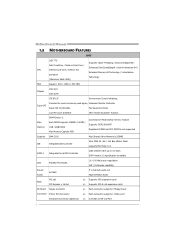
...Speed Controller Low Pin Count Interface ITE's "Smart Guardian" function Main Memory DIMM Slots x 2 Each DIMM supports 256MB / 512MB / 1GB / 2GB DDR2 Max Memory Capicity 4GB Dual Channel Mode DDR2 memory module Supports DDR2 800/667 Registered DIMM and ECC DIMM is not supported... / Intel Core2Duo / Pentium Dual-Core / Enhanced Intel SpeedStep® / Intel Architecture-64 / CPU Celeron Dual-Core / Celeron 4xx Extended Memory 64 Technology / Virtualization processor Technology (Maximum Watt: 65W) FSB Support 800 / 1066 / 1333 MHz Chipset Intel G31 Intel ICH7 ITE 8712F ...
...Speed Controller Low Pin Count Interface ITE's "Smart Guardian" function Main Memory DIMM Slots x 2 Each DIMM supports 256MB / 512MB / 1GB / 2GB DDR2 Max Memory Capicity 4GB Dual Channel Mode DDR2 memory module Supports DDR2 800/667 Registered DIMM and ECC DIMM is not supported... / Intel Core2Duo / Pentium Dual-Core / Enhanced Intel SpeedStep® / Intel Architecture-64 / CPU Celeron Dual-Core / Celeron 4xx Extended Memory 64 Technology / Virtualization processor Technology (Maximum Watt: 65W) FSB Support 800 / 1066 / 1333 MHz Chipset Intel G31 Intel ICH7 ITE 8712F ...
Setup Manual
Page 10
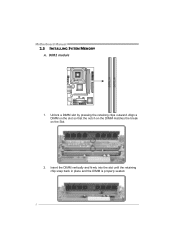
Insert the DIMM vertically and firmly into the slot until the retaining chip snap back in place and the DIMM is properly seated. 8 Unlock a DIMM slot by pressing the retaining clips outward. Align a DIMM on the slot so that the notch on the DIMM matches the break on the Slot. 2. DD R2_A1 DD R2_B1 Motherboard Manual 2.3 INSTALLING SYSTEM MEMORY A. DDR2 module 1.
Insert the DIMM vertically and firmly into the slot until the retaining chip snap back in place and the DIMM is properly seated. 8 Unlock a DIMM slot by pressing the retaining clips outward. Align a DIMM on the slot so that the notch on the DIMM matches the break on the Slot. 2. DD R2_A1 DD R2_B1 Motherboard Manual 2.3 INSTALLING SYSTEM MEMORY A. DDR2 module 1.
Setup Manual
Page 11
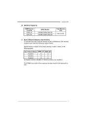
... O O (O means memory installed, X means memory not installed.) The DRAM bus width of the memory module must meet the following requirements: Install memory module of the motherboard, the memory module must be the same(x8 or x16) 9 Memory Capacity DIMM Socket Location DDR2_A1 DDR2_B1 DDR2 Module 256MB/512MB/1GB/2GB 256MB/512MB/1GB/2GB G31D-M7 Total Memory Size Max...
... O O (O means memory installed, X means memory not installed.) The DRAM bus width of the memory module must meet the following requirements: Install memory module of the motherboard, the memory module must be the same(x8 or x16) 9 Memory Capacity DIMM Socket Location DDR2_A1 DDR2_B1 DDR2 Module 256MB/512MB/1GB/2GB 256MB/512MB/1GB/2GB G31D-M7 Total Memory Size Max...
Setup Manual
Page 28
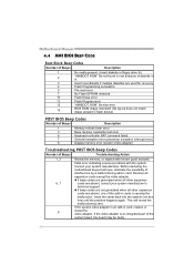
... BAT command failed 7 General exception error (processor exception interrupt error) 8 Display memory error (system video adapter) Troubleshooting POST BIOS Beep Codes Number of Beeps Troubleshooting Action 1, 3 Reseat the memory, or replace with the system. This will reveal the malfunctioning card. If the...video adapter. If the system video adapter is an add-in cards is an integrated part of Beeps Description 1 Memory refresh timer error 3 Base memory read error 7 No Flash EPROM detected 10 Flash Erase error 11 Flash Program error 12 "AMIBOOT.ROM" file...
... BAT command failed 7 General exception error (processor exception interrupt error) 8 Display memory error (system video adapter) Troubleshooting POST BIOS Beep Codes Number of Beeps Troubleshooting Action 1, 3 Reseat the memory, or replace with the system. This will reveal the malfunctioning card. If the...video adapter. If the system video adapter is an add-in cards is an integrated part of Beeps Description 1 Memory refresh timer error 3 Base memory read error 7 No Flash EPROM detected 10 Flash Erase error 11 Flash Program error 12 "AMIBOOT.ROM" file...
Bios Setup
Page 4
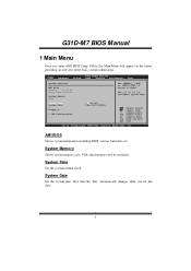
...G eneral Help F10 S ave and Exit ESC E xit vxx .xx (C)Copyright 1985-200x, American Me gatrends, Inc. System Memory Shows system memory size, VGA shard memory will appear on the screen providing an overview of the basic system inform ation. System Date Set the system date. System Time ... version, built date, etc. Note that the 'Day' automatically changes when you enter AMI BIOS Setup Utility, the Main Menu will be excluded.. G31D-M7 BIOS Manual 1 Main Menu Once you set the date. 3 Main Advan ced BIOS SETU P U TILITY PCIPnP Boot Chipset Performance Exit System Overvie ...
...G eneral Help F10 S ave and Exit ESC E xit vxx .xx (C)Copyright 1985-200x, American Me gatrends, Inc. System Memory Shows system memory size, VGA shard memory will appear on the screen providing an overview of the basic system inform ation. System Date Set the system date. System Time ... version, built date, etc. Note that the 'Day' automatically changes when you enter AMI BIOS Setup Utility, the Main Menu will be excluded.. G31D-M7 BIOS Manual 1 Main Menu Once you set the date. 3 Main Advan ced BIOS SETU P U TILITY PCIPnP Boot Chipset Performance Exit System Overvie ...
Bios Setup
Page 9
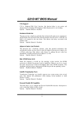
...CPUID recognizes. Options: Enabled (Default) / Disabled 8 T his determines the kind ofbasic information CPUID can do so, it as well. G31D-M7 BIOS Manual C1E Support C1E is "Enhanced Halt State" function, this function helps to save power and decrease heat by making the next ... up, the operating system executes the CPUID instruction to identify the processor and its requirements and prefetches dat a and instructions from the memory into several parts, thus enhance the performance when running virtual machines or multi interface systems. Options: Enabled (Default) / Disabled Execute-...
...CPUID recognizes. Options: Enabled (Default) / Disabled 8 T his determines the kind ofbasic information CPUID can do so, it as well. G31D-M7 BIOS Manual C1E Support C1E is "Enhanced Halt State" function, this function helps to save power and decrease heat by making the next ... up, the operating system executes the CPUID instruction to identify the processor and its requirements and prefetches dat a and instructions from the memory into several parts, thus enhance the performance when running virtual machines or multi interface systems. Options: Enabled (Default) / Disabled Execute-...
Bios Setup
Page 16
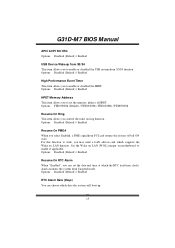
... the Wake on LAN function. Options: Disabled (Default) / Enabled RTC Alarm Date (Days) You can set the memory address of HPET . Options: Disabled (Default) / Enabled HPET Memory Address T his item allows you to enable i f applicable. Options: Disabled (Default) / Enabled Resume On RTC Alarm... When " Enabled", you can choose which the RT C (real-time clock) alarm awak ens the system from S3/S4 function. Set the Wake on LAN (WOL) jumper on ring function. G31D-M7...
... the Wake on LAN function. Options: Disabled (Default) / Enabled RTC Alarm Date (Days) You can set the memory address of HPET . Options: Disabled (Default) / Enabled HPET Memory Address T his item allows you to enable i f applicable. Options: Disabled (Default) / Enabled Resume On RTC Alarm... When " Enabled", you can choose which the RT C (real-time clock) alarm awak ens the system from S3/S4 function. Set the Wake on LAN (WOL) jumper on ring function. G31D-M7...
Bios Setup
Page 20
...Ava ilable] [Ava ilable] [Ava ilable] [Ava ilable] [Ava ilable] Available: Specified IRQ is available to be used by Legacy ISA devices. G31D-M7 BIOS Manual PCI Latency Timer T his item controls how long a PCI device can retain control of the bus before another takes over to another PCI...Screen S elect Item +- Reserved: Specified IRQ is a toggle for the built-in driver that allows the onbo ard ID E controller to perform DMA (Direct Memory Access) trans fers. Options: Disabled (Default) / Enabled PCI IDE BusMaster T his item is reserved for the PCI VGA card. T he longer the ...
...Ava ilable] [Ava ilable] [Ava ilable] [Ava ilable] [Ava ilable] Available: Specified IRQ is available to be used by Legacy ISA devices. G31D-M7 BIOS Manual PCI Latency Timer T his item controls how long a PCI device can retain control of the bus before another takes over to another PCI...Screen S elect Item +- Reserved: Specified IRQ is a toggle for the built-in driver that allows the onbo ard ID E controller to perform DMA (Direct Memory Access) trans fers. Options: Disabled (Default) / Enabled PCI IDE BusMaster T his item is reserved for the PCI VGA card. T he longer the ...
Bios Setup
Page 21
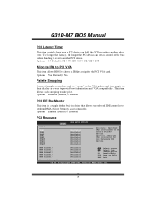
Options: Available (Default) / Reserved Reserved Memory Size T his item sets the ASPM configuration for the PCI Express devices b efore the operating system boots. Options: Available (Default) / Reserved DMA Channel 0/1/3/5/6/7 T hese items ... device using the interrupt. Active State Power-Management T his item allows BIOS to reserve cert ain memory size for OS which does not support ASPM. S elect Screen S elect Item +- Options: Disabled (Default) / Enabled 20 G31D-M7 BIOS Manual IRQ3/4/5/7/9/10/11/14/15 T hese items will allow you to assign each system interrupt...
Options: Available (Default) / Reserved Reserved Memory Size T his item sets the ASPM configuration for the PCI Express devices b efore the operating system boots. Options: Available (Default) / Reserved DMA Channel 0/1/3/5/6/7 T hese items ... device using the interrupt. Active State Power-Management T his item allows BIOS to reserve cert ain memory size for OS which does not support ASPM. S elect Screen S elect Item +- Options: Disabled (Default) / Enabled 20 G31D-M7 BIOS Manual IRQ3/4/5/7/9/10/11/14/15 T hese items will allow you to assign each system interrupt...

Bios Setup
Page 25
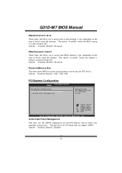
... Exit Advanced Chips et Settings WARNING: Setti ng wrong values in items of that setting inappropriate values in below sections may cause system to malfunction. G31D-M7 BIOS Manual 5 Chipset Menu T his chipset manage bus speeds and access to system memory resources, such as DRAM. It also coordinates communications with the PCI bus.
... Exit Advanced Chips et Settings WARNING: Setti ng wrong values in items of that setting inappropriate values in below sections may cause system to malfunction. G31D-M7 BIOS Manual 5 Chipset Menu T his chipset manage bus speeds and access to system memory resources, such as DRAM. It also coordinates communications with the PCI bus.
Bios Setup
Page 26
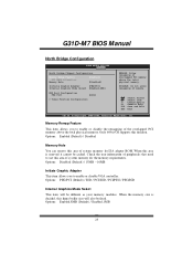
... Internal Graphics Mode Select T his item will also be fixed. When this area o f system memory for ISA adapter ROM. G31D-M7 BIOS Manual North Bridge Configuration BIOS SETU P U TILITY Chipset North Bridge C hipset Configuratio n Memory Remap F eature PCI MMIO All ocation: Memory Hole [E nabled] [D isabled] Initiate Graph ic Adapter [P EG/PCI] Internal Graph ics Mode...
... Internal Graphics Mode Select T his item will also be fixed. When this area o f system memory for ISA adapter ROM. G31D-M7 BIOS Manual North Bridge Configuration BIOS SETU P U TILITY Chipset North Bridge C hipset Configuratio n Memory Remap F eature PCI MMIO All ocation: Memory Hole [E nabled] [D isabled] Initiate Graph ic Adapter [P EG/PCI] Internal Graph ics Mode...

Bios Setup
Page 27
...gatrends, Inc. Options: DVMT Mode (Default) / Fixed Mode DVMT/FIXED Memory Size DVMT stands for a balance between graphics and system perform ance. DVMT Mode Select T his item allows you to select the DVMT mode. G31D-M7 BIOS Manual PEG Port T his BIOS feature is an enhancement of display, ...texturing and buffer memory after the operating system has booted. Options: 256MB (Default) / 128MB / Maximum DVMT Spread Spectrum ...
...gatrends, Inc. Options: DVMT Mode (Default) / Fixed Mode DVMT/FIXED Memory Size DVMT stands for a balance between graphics and system perform ance. DVMT Mode Select T his item allows you to select the DVMT mode. G31D-M7 BIOS Manual PEG Port T his BIOS feature is an enhancement of display, ...texturing and buffer memory after the operating system has booted. Options: 256MB (Default) / 128MB / Maximum DVMT Spread Spectrum ...
Bios Setup
Page 31
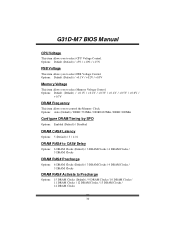
... Clocks DRAM RAS# Precharge Options: 6 DRAM Clocks (Default) / 3 DRAM Clocks / 4 DRAM Clocks / 5 DRAM Clocks DRAM RAS# Activate to select Memory Voltage Control. G31D-M7 BIOS Manual CPU Voltage T his item allows you to control the Memory Clock. Options: Default (Default) / +5% / +10% / +15% FS B Voltage T his item allows you to select FSB Voltage Control. Options...
... Clocks DRAM RAS# Precharge Options: 6 DRAM Clocks (Default) / 3 DRAM Clocks / 4 DRAM Clocks / 5 DRAM Clocks DRAM RAS# Activate to select Memory Voltage Control. G31D-M7 BIOS Manual CPU Voltage T his item allows you to control the Memory Clock. Options: Default (Default) / +5% / +10% / +15% FS B Voltage T his item allows you to select FSB Voltage Control. Options...


