Bios Setup
Page 2
... to modify the basic system configuration and save these settings to describe the settings in the Phoenix-Award™ BIOS Setup program on this motherboard. This system controls most of the booting process, loading and executing the operating system. Plug and Play Support This PHOENIX-AWARD BIOS supports ...disk drives and video monitors can do without accessing programs from a disk. Power to guide you through the options and settings in BIOS. G31-M7/P31-A7 BIOS Setup Introduction The purpose of this manual is to CMOS RAM. The power of CMOS RAM is supplied by this PHOENIX-AWARD...
... to modify the basic system configuration and save these settings to describe the settings in the Phoenix-Award™ BIOS Setup program on this motherboard. This system controls most of the booting process, loading and executing the operating system. Plug and Play Support This PHOENIX-AWARD BIOS supports ...disk drives and video monitors can do without accessing programs from a disk. Power to guide you through the options and settings in BIOS. G31-M7/P31-A7 BIOS Setup Introduction The purpose of this manual is to CMOS RAM. The power of CMOS RAM is supplied by this PHOENIX-AWARD...
Setup Manual
Page 2
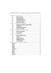
Table of Contents Chapter 1: Introduction 1 1.1 Before You Start 1 1.2 Package Checklist 1 1.3 Motherboard Features 2 1.4 Rear Panel Connectors 3 1.5 Motherboard Layout 4 Chapter 2: Hardware Installation 5 2.1 Installing Central Processing Unit (CPU 5 2.2 FAN Headers 7 2.3 Installing System Memory 8 2.4 Connectors and Slots 10 Chapter 3: Headers & Jumpers Setup 12 3.1 How to ...
Table of Contents Chapter 1: Introduction 1 1.1 Before You Start 1 1.2 Package Checklist 1 1.3 Motherboard Features 2 1.4 Rear Panel Connectors 3 1.5 Motherboard Layout 4 Chapter 2: Hardware Installation 5 2.1 Installing Central Processing Unit (CPU 5 2.2 FAN Headers 7 2.3 Installing System Memory 8 2.4 Connectors and Slots 10 Chapter 3: Headers & Jumpers Setup 12 3.1 How to ...
Setup Manual
Page 3
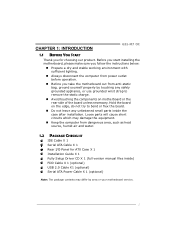
... the rear side of the board unless necessary. Before you start installing the motherboard, please make sure you follow the instructions below: „ Prepare a dry and stable working environment with sufficient lighting. „ Always disconnect the computer from... to bend or flex the board. „ Do not leave any unfastened small parts inside the case after installation. CHAPTER 1: INTRODUCTION G31-M7 OC 1.1 BEFORE YOU START Thank you take the motherboard out from dangerous area, such as heat source, humid air and water. 1.2 PACKAGE CHECKLIST IDE Cable X 1 Serial ATA Cable X 1 Rear ...
... the rear side of the board unless necessary. Before you start installing the motherboard, please make sure you follow the instructions below: „ Prepare a dry and stable working environment with sufficient lighting. „ Always disconnect the computer from... to bend or flex the board. „ Do not leave any unfastened small parts inside the case after installation. CHAPTER 1: INTRODUCTION G31-M7 OC 1.1 BEFORE YOU START Thank you take the motherboard out from dangerous area, such as heat source, humid air and water. 1.2 PACKAGE CHECKLIST IDE Cable X 1 Serial ATA Cable X 1 Rear ...
Setup Manual
Page 4
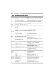
Motherboard Manual 1.3 MOTHERBOARD FEATURES SPEC LGA 775 Supports Hyper-Threading / Execute Disable Bit / Intel Core2Duo / Core2Quad / Enhanced Intel SpeedStep® / Intel Architecture-64 / CPU Pentium Dual-Core / Celeron Dual-Core / Extended Memory 64 Technology / Virtualization Celeron 4xx processor Technology FSB Support 800 / 1066 / 1333 / 1600 MHz Chipset Intel G31 Intel ICH7 ITE 8712F Environment...
Motherboard Manual 1.3 MOTHERBOARD FEATURES SPEC LGA 775 Supports Hyper-Threading / Execute Disable Bit / Intel Core2Duo / Core2Quad / Enhanced Intel SpeedStep® / Intel Architecture-64 / CPU Pentium Dual-Core / Celeron Dual-Core / Extended Memory 64 Technology / Virtualization Celeron 4xx processor Technology FSB Support 800 / 1066 / 1333 / 1600 MHz Chipset Intel G31 Intel ICH7 ITE 8712F Environment...

Setup Manual
Page 6
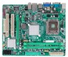
Motherboard Manual 1.5 MOTHERBOARD LAYOUT JKBMS1 JATXPWR2 LGA775 CPU1 JCFAN1 JATXPWR1 DDR2_A1 DDR2_B1 JVGA1 JUSBV1 JUSB2 JRJ45USB1 I nt el G31 IDE1 JAUDIO1 BIOS JAUDIOF1 LAN BATTERY PEX16_1 Super I/O Codec PCI1 JPRNT1 PCI2 JCOM2 Intel ICH7 JUSB3 FDD1 JSFAN1 JUSB4 JPANEL1 JCMOS1 SATA1 SATA2 Note: ■ represents the 1st pin. SATA4 SATA3 4
Motherboard Manual 1.5 MOTHERBOARD LAYOUT JKBMS1 JATXPWR2 LGA775 CPU1 JCFAN1 JATXPWR1 DDR2_A1 DDR2_B1 JVGA1 JUSBV1 JUSB2 JRJ45USB1 I nt el G31 IDE1 JAUDIO1 BIOS JAUDIOF1 LAN BATTERY PEX16_1 Super I/O Codec PCI1 JPRNT1 PCI2 JCOM2 Intel ICH7 JUSB3 FDD1 JSFAN1 JUSB4 JPANEL1 JCMOS1 SATA1 SATA2 Note: ■ represents the 1st pin. SATA4 SATA3 4

Setup Manual
Page 8
This completes the installation. 6 Motherboard Manual Step 2: Look for the triangular cut edge. Connect the CPU FAN power cable into the JCFAN1. Step 4: Put the CPU Fan and heatsink assembly on the CPU and buckle it on CPU should point forwards this triangular cut edge on socket, and the golden dot on the retention frame. Step 2-1: Step 2-2: Step 3: Hold the CPU down firmly, and then lower the lever to locked position to complete the installation. The CPU will fit only in the correct orientation.
This completes the installation. 6 Motherboard Manual Step 2: Look for the triangular cut edge. Connect the CPU FAN power cable into the JCFAN1. Step 4: Put the CPU Fan and heatsink assembly on the CPU and buckle it on CPU should point forwards this triangular cut edge on socket, and the golden dot on the retention frame. Step 2-1: Step 2-2: Step 3: Hold the CPU down firmly, and then lower the lever to locked position to complete the installation. The CPU will fit only in the correct orientation.
Setup Manual
Page 10
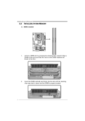
Align a DIMM on the slot such that the notch on the DIMM matches the break on the Slot. 2. Insert the DIMM vertically and firmly into the slot until the retaining chip snap back in place and the DIMM is properly seated. 8 DDR2_A 1 DDR2_B 1 Motherboard Manual 2.3 INSTALLING SYSTEM MEMORY A. Unlock a DIMM slot by pressing the retaining clips outward. DDR2 module 1.
Align a DIMM on the slot such that the notch on the DIMM matches the break on the Slot. 2. Insert the DIMM vertically and firmly into the slot until the retaining chip snap back in place and the DIMM is properly seated. 8 DDR2_A 1 DDR2_B 1 Motherboard Manual 2.3 INSTALLING SYSTEM MEMORY A. Unlock a DIMM slot by pressing the retaining clips outward. DDR2 module 1.
Setup Manual
Page 11
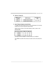
... bus width of the memory module must meet the following requirements: Install memory module of the motherboard, the memory module must be the same(x8 or x16) 9 B. Memory Capacity DIMM Socket Location DDR2_A1 DDR2_B1 DDR2 Module 256MB/512MB/1GB/2GB 256MB/512MB/1GB/2GB G31-M7 OC Total Memory Size Max is 4GB.
... bus width of the memory module must meet the following requirements: Install memory module of the motherboard, the memory module must be the same(x8 or x16) 9 B. Memory Capacity DIMM Socket Location DDR2_A1 DDR2_B1 DDR2 Module 256MB/512MB/1GB/2GB 256MB/512MB/1GB/2GB G31-M7 OC Total Memory Size Max is 4GB.
Setup Manual
Page 12
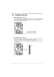
Motherboard Manual 2.4 CONNECTORS AND SLOTS FDD1: Floppy Disk Connector The motherboard provides a standard floppy disk connector that provides PIO Mode 0~4, Bus Master, and Ultra DMA 33/66/100 functionality. This connector supports the provided floppy drive ribbon cables. 2 34 1 33 IDE1: IDE/ATAPI Connector The motherboard has a 32-bit Enhanced PCI IDE Controller that supports 360K, 720K, 1.2M, 1.44M and 2.88M floppy disk types. The IDE connector can connect a master and a slave drive, so you can connect up to two drives. 40 39 2 1 10
Motherboard Manual 2.4 CONNECTORS AND SLOTS FDD1: Floppy Disk Connector The motherboard provides a standard floppy disk connector that provides PIO Mode 0~4, Bus Master, and Ultra DMA 33/66/100 functionality. This connector supports the provided floppy drive ribbon cables. 2 34 1 33 IDE1: IDE/ATAPI Connector The motherboard has a 32-bit Enhanced PCI IDE Controller that supports 360K, 720K, 1.2M, 1.44M and 2.88M floppy disk types. The IDE connector can connect a master and a slave drive, so you can connect up to two drives. 40 39 2 1 10
Setup Manual
Page 13
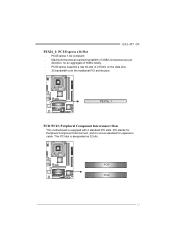
PEX16_1 PCI1/PCI2: Peripheral Component Interconnect Slots This motherboard is designated as 32 bits. This PCI slot is equipped with 2 standard PCI slots. PCI-Express supports a raw bit-rate of 8GB/s totally. - PCI1 PCI2 11 PCI-Express 1.0a compliant. - PCI stands for Peripheral Component Interconnect, and it is a bus standard for an aggregate of 2.5Gb/s on the data pins. - 2X bandwidth over the traditional PCI architecture. G31-M7 OC PEX16_1: PCI-Express x16 Slot - Maximum theoretical realized bandwidth of 4GB/s simultaneously per direction, for expansion cards.
PEX16_1 PCI1/PCI2: Peripheral Component Interconnect Slots This motherboard is designated as 32 bits. This PCI slot is equipped with 2 standard PCI slots. PCI-Express supports a raw bit-rate of 8GB/s totally. - PCI1 PCI2 11 PCI-Express 1.0a compliant. - PCI stands for Peripheral Component Interconnect, and it is a bus standard for an aggregate of 2.5Gb/s on the data pins. - 2X bandwidth over the traditional PCI architecture. G31-M7 OC PEX16_1: PCI-Express x16 Slot - Maximum theoretical realized bandwidth of 4GB/s simultaneously per direction, for expansion cards.
Setup Manual
Page 14
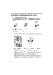
Motherboard Manual CHAPTER 3: HEADERS & JUMPERS SETUP 3.1 HOW TO SETUP JUMPERS The illustration shows how to connect the PC case's front panel switch functions. - PWR_LED On/Off 9 ++ ...
Motherboard Manual CHAPTER 3: HEADERS & JUMPERS SETUP 3.1 HOW TO SETUP JUMPERS The illustration shows how to connect the PC case's front panel switch functions. - PWR_LED On/Off 9 ++ ...

Setup Manual
Page 16
... to connect additional USB cable on the PC front panel, and also can be connected with the PC front panel. Motherboard Manual JUSB3/JUSB4: Headers for USB 2.0 Ports at Front Panel This motherboard provides 2 USB 2.0 headers, which allows user to connect the front audio output cable with internal USB devices, like USB...
... to connect additional USB cable on the PC front panel, and also can be connected with the PC front panel. Motherboard Manual JUSB3/JUSB4: Headers for USB 2.0 Ports at Front Panel This motherboard provides 2 USB 2.0 headers, which allows user to connect the front audio output cable with internal USB devices, like USB...

Setup Manual
Page 17
... RX6 RX+ 7 Ground 7 41 15 Wait for five seconds. 4. Set the jumper to "Pin 2-3 close ". 5. SATA1~SATA4: Serial ATA Connectors The motherboard has a PCI to avoid damaging the motherboard. 3 1 Pin 1-2 Close: Normal Operation (Default). 3 1 3 1 Pin 2-3 Close: Clear CMOS data. ※ Clear CMOS Procedures: 1. Power on... follow the procedures to SATA Controller with 4channels SATA interface, it satisfies the SATA 2.0 spec and with transfer rate of 3Gb/s. G31-M7 OC JCMOS1: Clear CMOS Header By placing the jumper on the AC. 6. Reset your desired password or clear the CMOS data....
... RX6 RX+ 7 Ground 7 41 15 Wait for five seconds. 4. Set the jumper to "Pin 2-3 close ". 5. SATA1~SATA4: Serial ATA Connectors The motherboard has a PCI to avoid damaging the motherboard. 3 1 Pin 1-2 Close: Normal Operation (Default). 3 1 3 1 Pin 2-3 Close: Clear CMOS data. ※ Clear CMOS Procedures: 1. Power on... follow the procedures to SATA Controller with 4channels SATA interface, it satisfies the SATA 2.0 spec and with transfer rate of 3Gb/s. G31-M7 OC JCMOS1: Clear CMOS Header By placing the jumper on the AC. 6. Reset your desired password or clear the CMOS data....

Setup Manual
Page 18
Pin 2-3 Close: +5V STB for USB ports at JUSB2/JRJ45USB1. 3 1 3 1 Pin 1-2 close 3 1 Pin 2-3 close JCOM2: Serial port Connector The motherboard has a Serial Port Connector for USB ports at JUSB2/JRJ45USB1. Motherboard Manual JUSBV1: Power Source Header for USB Ports Pin 1-2 Close: +5V for connecting RS-232 Port. 2 10 1 9 Pin Assignment 1 Carrier detect 2 Received data 3 Transmitted data 4 Data terminal ready 5 Signal ground 6 Data set ready 7 Request to send 8 Clear to send 9 Ring indicator 10 Key 16
Pin 2-3 Close: +5V STB for USB ports at JUSB2/JRJ45USB1. 3 1 3 1 Pin 1-2 close 3 1 Pin 2-3 close JCOM2: Serial port Connector The motherboard has a Serial Port Connector for USB ports at JUSB2/JRJ45USB1. Motherboard Manual JUSBV1: Power Source Header for USB Ports Pin 1-2 Close: +5V for connecting RS-232 Port. 2 10 1 9 Pin Assignment 1 Carrier detect 2 Received data 3 Transmitted data 4 Data terminal ready 5 Signal ground 6 Data set ready 7 Request to send 8 Clear to send 9 Ring indicator 10 Key 16

Setup Manual
Page 20
...will list the compatible driver for your optical drive. A. Click on the Manual icon to locate and execute the file SETUP.EXE under your motherboard and operating system. B. C. You will see the following window after you insert the Driver CD, please use file browser to browse for...performance. Note: If this window didn't show up after you installed your operating system, please insert the Fully Setup Driver CD into your motherboard and operating system. Driver Installation To install the driver, please click on the Software icon. The setup guide will auto detect your optical...
...will list the compatible driver for your optical drive. A. Click on the Manual icon to locate and execute the file SETUP.EXE under your motherboard and operating system. B. C. You will see the following window after you insert the Driver CD, please use file browser to browse for...performance. Note: If this window didn't show up after you installed your operating system, please insert the Fully Setup Driver CD into your motherboard and operating system. Driver Installation To install the driver, please click on the Software icon. The setup guide will auto detect your optical...

Setup Manual
Page 22
... asking you to a .txt file, click "Save As..." If you may need to save this information, click "Send" to the following web http://www.biostar.com.tw/app/en-us/about/contact.php for your confirmation; If you are not using eHot-Line service. Open the saved .txt file, you... application. This information is also concluded in the sent mail. Go to send the mail out. Your system information will see your system information including motherboard/BIOS/CPU/video/ device/OS information. click "Send" to confirm or "Do Not Send" to a .txt file. Enter the file name and then click "...
... asking you to a .txt file, click "Save As..." If you may need to save this information, click "Send" to the following web http://www.biostar.com.tw/app/en-us/about/contact.php for your confirmation; If you are not using eHot-Line service. Open the saved .txt file, you... application. This information is also concluded in the sent mail. Go to send the mail out. Your system information will see your system information including motherboard/BIOS/CPU/video/ device/OS information. click "Send" to confirm or "Do Not Send" to a .txt file. Enter the file name and then click "...
Setup Manual
Page 23
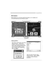
... saving dialog will show . G31-M7 OC BIOS Update BIOS Update is a convenient utility which allows you to save file and enter file name. (We recommend that the file name should be English/number and no longer than 7 characters.) Then click Save. Choose the position to update your motherboard BIOS under Windows system.
... saving dialog will show . G31-M7 OC BIOS Update BIOS Update is a convenient utility which allows you to save file and enter file name. (We recommend that the file name should be English/number and no longer than 7 characters.) Then click Save. Choose the position to update your motherboard BIOS under Windows system.

Setup Manual
Page 24
... procedure, the open any other applications during this procedure. Please do not open dialog will show for BIOS backup and refer to exit BIOS setup. Motherboard Manual Before doing this process may take minutes. For AWARD BIOS, update BIOS procedure should be updated. or click No to be run with the...
... procedure, the open any other applications during this procedure. Please do not open dialog will show for BIOS backup and refer to exit BIOS setup. Motherboard Manual Before doing this process may take minutes. For AWARD BIOS, update BIOS procedure should be updated. or click No to be run with the...
Setup Manual
Page 26
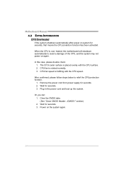
.... Plug in the power cord and boot up the system. In this case, please double check: 1. CPU fan speed is over heated, the motherboard will shutdown automatically to relief the CPU protection function. 1. Wait for seconds, that means the CPU protection function has been activated.... Motherboard Manual 4.3 EXTRA INFORMATION CPU Overheated If the system shutdown automatically after power on the system again. 24 When the CPU is fulfilling with ...
.... Plug in the power cord and boot up the system. In this case, please double check: 1. CPU fan speed is over heated, the motherboard will shutdown automatically to relief the CPU protection function. 1. Wait for seconds, that means the CPU protection function has been activated.... Motherboard Manual 4.3 EXTRA INFORMATION CPU Overheated If the system shutdown automatically after power on the system again. 24 When the CPU is fulfilling with ...
Setup Manual
Page 27
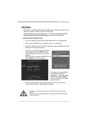
... the USB pen drive or the floppy disk that contains the BIOS file to download the latest BIOS file for the motherboard. 2. The utility will lead to reboot the system. G31-M7 OC BIO-Flasher BIO-Flasher is built in the BIOS chip. Go to the website to the USB port or the...
... the USB pen drive or the floppy disk that contains the BIOS file to download the latest BIOS file for the motherboard. 2. The utility will lead to reboot the system. G31-M7 OC BIO-Flasher BIO-Flasher is built in the BIOS chip. Go to the website to the USB port or the...


