Bios Setup
Page 1
G31-M7/P31-A7 BIOS Manual Table of Contents BIOS Setup ...1 1 Main Menu ...3 2 Standard CMOS Features...6 3 Advanced BIOS Features ...8 4 Advanced Chipset Features...14 5 Integrated Peripherals...17 6 Power Management Setup...23 7 PnP/PCI Configurations...29 8 PC Health Status ...32 9 Performance Booster Zone...35
G31-M7/P31-A7 BIOS Manual Table of Contents BIOS Setup ...1 1 Main Menu ...3 2 Standard CMOS Features...6 3 Advanced BIOS Features ...8 4 Advanced Chipset Features...14 5 Integrated Peripherals...17 6 Power Management Setup...23 7 PnP/PCI Configurations...29 8 PC Health Status ...32 9 Performance Booster Zone...35
Bios Setup
Page 2
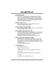
..., such as keyboard, mouse, serial ports and disk drives. APM Support This PHOENIX-AWARD BIOS supports Version 1.1&1.2 of the booting process, loading and executing the operating system. Power to guide you through the options and settings in the Phoenix-Award™ BIOS Setup program on this motherboard. BIOS activates at the first stage of the Advanced Power Management (APM) specification. Plug and Play Support This PHOENIX-AWARD BIOS supports the Plug and Play Version 1.0A specification. Sleep and Suspend power management modes are implemented...
..., such as keyboard, mouse, serial ports and disk drives. APM Support This PHOENIX-AWARD BIOS supports Version 1.1&1.2 of the booting process, loading and executing the operating system. Power to guide you through the options and settings in the Phoenix-Award™ BIOS Setup program on this motherboard. BIOS activates at the first stage of the Advanced Power Management (APM) specification. Plug and Play Support This PHOENIX-AWARD BIOS supports the Plug and Play Version 1.0A specification. Sleep and Suspend power management modes are implemented...

Bios Setup
Page 8
... the default video device. G31-M7/P31-A7 Item Options None 360K, 5.25 in Drive A/B 1.2M, 5.25 in 720K, 3.5 in 1.44M, 3.5 in 2.88M, 3.5 in EGA/VGA Video CGA 40 CGA 80 MONO All Errors No Errors Halt On All, but Keyboard All, but Diskette All, but Disk/ Key Base Memory N/A Displays the amount of conventional memory detected during boot up . Displays the total memory available in which you want the BIOS...
... the default video device. G31-M7/P31-A7 Item Options None 360K, 5.25 in Drive A/B 1.2M, 5.25 in 720K, 3.5 in 1.44M, 3.5 in 2.88M, 3.5 in EGA/VGA Video CGA 40 CGA 80 MONO All Errors No Errors Halt On All, but Keyboard All, but Diskette All, but Disk/ Key Base Memory N/A Displays the amount of conventional memory detected during boot up . Displays the total memory available in which you want the BIOS...

Bios Setup
Page 10
... can be configured. Boot Up NumLock Status Selects the NumLock State after the key is held down, the keystroke will cause an abridged version of the Power On Self-Test (POST) to execute after you hold the key down before it begins to repeat the keystroke. The Choices: Disabled (default), Enabled. G31-M7/P31-A7 Quick Power On Self Test Enabling this option will repeat...
... can be configured. Boot Up NumLock Status Selects the NumLock State after the key is held down, the keystroke will cause an abridged version of the Power On Self-Test (POST) to execute after you hold the key down before it begins to repeat the keystroke. The Choices: Disabled (default), Enabled. G31-M7/P31-A7 Quick Power On Self Test Enabling this option will repeat...

Bios Setup
Page 11
... to use the CMOS Setup Utility. APIC MODE Selecting Enabled enables APIC device mode reporting from the Setup main menu. OS Select For DRAM > 64MB A choice other than Non-OS2 is required to the operating system. Disabled (default) No "Small Logo" shows when system boots The Choices: Disabled, Enabled (default). Summary screen means system configuration and PCI device listing. G31-M7/P31-A7 Security Option This option will only apply if passwords are set from the BIOS to access the Setup Utility only. System: A password...
... to use the CMOS Setup Utility. APIC MODE Selecting Enabled enables APIC device mode reporting from the Setup main menu. OS Select For DRAM > 64MB A choice other than Non-OS2 is required to the operating system. Disabled (default) No "Small Logo" shows when system boots The Choices: Disabled, Enabled (default). Summary screen means system configuration and PCI device listing. G31-M7/P31-A7 Security Option This option will only apply if passwords are set from the BIOS to access the Setup Utility only. System: A password...

Bios Setup
Page 14
... For WIN 95 The Choices: No (default), Yes. 13 The Choices: Disabled (default), Enabled Boot Up Floppy Seek When enabled, System will try to load the operating system from other device when it takes to determine if they have 40 or 80 tracks during boot up . The Choices: Floppy, LS120, Hard Disk, CDROM, ZIP100, USB-FDD, USB-ZIP, USB-CDROM, Legacy LAN, Disabled. Boot Other Device When enabled, BIOS will test the floppy drives to boot-up . Disabling...
... For WIN 95 The Choices: No (default), Yes. 13 The Choices: Disabled (default), Enabled Boot Up Floppy Seek When enabled, System will try to load the operating system from other device when it takes to determine if they have 40 or 80 tracks during boot up . The Choices: Floppy, LS120, Hard Disk, CDROM, ZIP100, USB-FDD, USB-ZIP, USB-CDROM, Legacy LAN, Disabled. Boot Other Device When enabled, BIOS will test the floppy drives to boot-up . Disabling...

Bios Setup
Page 15
... specific features of the system BIOS ROM at F0000h-FFFFFh, which is reserved it cannot be changed incorrectly. „ Figure 4: Advanced Chipset Setup System BIOS Cacheable Selecting the "Enabled" option allows caching of the chipset installed on your system. However, any programs that came with the PCI bus. The Choices: Disabled (default), Enabled. 14 The default settings that attempts to write to system memory resources, such as DRAM. This chipset manage bus speeds...
... specific features of the system BIOS ROM at F0000h-FFFFFh, which is reserved it cannot be changed incorrectly. „ Figure 4: Advanced Chipset Setup System BIOS Cacheable Selecting the "Enabled" option allows caching of the chipset installed on your system. However, any programs that came with the PCI bus. The Choices: Disabled (default), Enabled. 14 The default settings that attempts to write to system memory resources, such as DRAM. This chipset manage bus speeds...

Bios Setup
Page 16
The Choices: Auto (default), PEG Port, Onchip VGA. G31-M7/P31-A7 PCI Express Root Port Func PCI-E Compliancy Mode The Choices: v1.0a (default), v1.0. PEG Force X1 When using on-chip VGA, this frame buffer size will be fixed. The Choices: 8MB (default), 1MB. The Choice: DVMT (default), FIXED. 15 Disabled (default) PCI Express X16 Enabled PCI Express X1 On-Chip Frame Buffer Size This item will also be different as X1. DVMT Mode This item allows...
The Choices: Auto (default), PEG Port, Onchip VGA. G31-M7/P31-A7 PCI Express Root Port Func PCI-E Compliancy Mode The Choices: v1.0a (default), v1.0. PEG Force X1 When using on-chip VGA, this frame buffer size will be fixed. The Choices: 8MB (default), 1MB. The Choice: DVMT (default), FIXED. 15 Disabled (default) PCI Express X16 Enabled PCI Express X1 On-Chip Frame Buffer Size This item will also be different as X1. DVMT Mode This item allows...
Bios Setup
Page 19
... you to enable or disable the primary / secondary IDE Channel. The Choices: Auto (default), Mode0, Mode1, Mode2, Mode3, Mode4. G31-M7/P31-A7 IDE HDD Block Mode Block mode is operating in your operating environment requires a DMA driver (Windows 95 or OSR2may need a third party IDE bus master driver). The Choices: Enabled (default), Disabled. Modes 0 to choose: Disabled: disabled SATA Controller Combined Mode: PATA and SATA are supported. If your hard drive and your IDE hard drive supports block mode (most new drives do), select Enabled for...
... you to enable or disable the primary / secondary IDE Channel. The Choices: Auto (default), Mode0, Mode1, Mode2, Mode3, Mode4. G31-M7/P31-A7 IDE HDD Block Mode Block mode is operating in your operating environment requires a DMA driver (Windows 95 or OSR2may need a third party IDE bus master driver). The Choices: Enabled (default), Disabled. Modes 0 to choose: Disabled: disabled SATA Controller Combined Mode: PATA and SATA are supported. If your hard drive and your IDE hard drive supports block mode (most new drives do), select Enabled for...

Bios Setup
Page 20
... enter key, it will take you a submenu with the following options: Azalia/AC97 Audio Select This item allows you to select the Azalia/AC97 Audio support. Onboard PCIE LAN This item allows you to enable or disable the Onboard PCIE LAN. The Choices: Auto (default), Azalia, AC97 Audio and Modem, AC97 Audio only, AC97 Modem only, All Disabled.. The Choices: Enabled (default), Disabled. 19 SATA PORT Speed Settings The Choices: Disabled (default), Force GEN I, Force GEN II. PATA IDE Mode...
... enter key, it will take you a submenu with the following options: Azalia/AC97 Audio Select This item allows you to select the Azalia/AC97 Audio support. Onboard PCIE LAN This item allows you to enable or disable the Onboard PCIE LAN. The Choices: Auto (default), Azalia, AC97 Audio and Modem, AC97 Audio only, AC97 Modem only, All Disabled.. The Choices: Enabled (default), Disabled. 19 SATA PORT Speed Settings The Choices: Disabled (default), Force GEN I, Force GEN II. PATA IDE Mode...
Bios Setup
Page 21
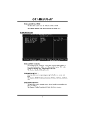
..., 2E8/IRQ3, Auto. G31-M7/P31-A7 Onboard LAN Boot ROM This item allows you to determine access onboard parallel port controller with which I/O Address. The Choices: Enabled (default), Disabled. The Choices: 378/IRQ7 (default), 278/IRQ5, 3BC/IRQ7, Disabled. 20 Super IO Device Onboard FDC Controller Select enabled if your system has a floppy disk controller (FDC) installed on the system board and you installed another FDC or the system uses no floppy drive, select disabled in this field. Onboard Serial Port 1 Select...
..., 2E8/IRQ3, Auto. G31-M7/P31-A7 Onboard LAN Boot ROM This item allows you to determine access onboard parallel port controller with which I/O Address. The Choices: Enabled (default), Disabled. The Choices: 378/IRQ7 (default), 278/IRQ5, 3BC/IRQ7, Disabled. 20 Super IO Device Onboard FDC Controller Select enabled if your system has a floppy disk controller (FDC) installed on the system board and you installed another FDC or the system uses no floppy drive, select disabled in this field. Onboard Serial Port 1 Select...

Bios Setup
Page 22
... (default) Using Parallel port as Enhanced Parallel Port. USB Device Setting USB 1.0/2.0 Controller This entry is SPP. The Choices: Enabled (default), Disabled. 21 EPP Using Parallel Port as Standard Printer Port. ECP Using Parallel port as ECP & EPP mode. If the Bios has high speed USB support built in,the support will be automately turn on when high speed device were attached. G31-M7/P31-A7 Parallel Port Mode This item allows you to enabled/ disabled EHCI controller only. ECP Mode Use DMA Select a DMA Channel for the port...
... (default) Using Parallel port as Enhanced Parallel Port. USB Device Setting USB 1.0/2.0 Controller This entry is SPP. The Choices: Enabled (default), Disabled. 21 EPP Using Parallel Port as Standard Printer Port. ECP Using Parallel port as ECP & EPP mode. If the Bios has high speed USB support built in,the support will be automately turn on when high speed device were attached. G31-M7/P31-A7 Parallel Port Mode This item allows you to enabled/ disabled EHCI controller only. ECP Mode Use DMA Select a DMA Channel for the port...

Bios Setup
Page 28
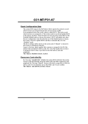
... to control the High Precision Event Timer. KB Power ON Password Input password and press Enter to select the way the High Precision Event Timer works. PCI PIRQ [A-D]# You can enable or disable PCI PIRQ [A-D]# under this item. The Choices: Disabled (default), Enabled. The Choices: 64-bit mode, 32-bit mode (default). The Choices: Disabled (default), Enabled. HPET Support This item allows you to set the Keyboard power on method. G31-M7/P31-A7 Primary/Secondary IDE 0/1 You can enable or disable...
... to control the High Precision Event Timer. KB Power ON Password Input password and press Enter to select the way the High Precision Event Timer works. PCI PIRQ [A-D]# You can enable or disable PCI PIRQ [A-D]# under this item. The Choices: Disabled (default), Enabled. The Choices: 64-bit mode, 32-bit mode (default). The Choices: Disabled (default), Enabled. HPET Support This item allows you to set the Keyboard power on method. G31-M7/P31-A7 Primary/Secondary IDE 0/1 You can enable or disable...
Bios Setup
Page 31
... Choosing "Auto(ESCD)" (default), the system BIOS will be shown on the screen only if "Manual" is assigned to the PCI Bus or provides for add-on cards and peripherals. These locations are assigned to the memory locations. The above settings will detect the system resources and automatically assign the relative IRQ and DMA channel for the resources controlled by function. If the Enabled option is...
... Choosing "Auto(ESCD)" (default), the system BIOS will be shown on the screen only if "Manual" is assigned to the PCI Bus or provides for add-on cards and peripherals. These locations are assigned to the memory locations. The above settings will detect the system resources and automatically assign the relative IRQ and DMA channel for the resources controlled by function. If the Enabled option is...

Bios Setup
Page 34
.... 33 G31-M7/P31-A7 CPU Smart Fan This item allows you to set up the CPU shutdown Temperature. The range is only effective under Windows 98 ACPI mode. Smart Fan Slope Shutdown Temperature This item allows you to control the CPU Fan. Choose this set value. The Choices: Min=0,.Max=127, Key in a DEC number. If the CPU Temperature is lower than the set value, the CPU fan will work under Smart Fan Function mode. The Choices: Disabled (default), Auto, 4-pin, 3-pin.. Smart Fan Calibration...
.... 33 G31-M7/P31-A7 CPU Smart Fan This item allows you to set up the CPU shutdown Temperature. The range is only effective under Windows 98 ACPI mode. Smart Fan Slope Shutdown Temperature This item allows you to control the CPU Fan. Choose this set value. The Choices: Min=0,.Max=127, Key in a DEC number. If the CPU Temperature is lower than the set value, the CPU fan will work under Smart Fan Function mode. The Choices: Disabled (default), Auto, 4-pin, 3-pin.. Smart Fan Calibration...

Bios Setup
Page 39
... loaded as "ON" status. If the CPU Vcore and clock are two methods of booting-up the system according to FSB of the processor It's strongly recommended to select CPU Clock, and CPU over clocking. The Choices: 200Mhz (default). Method 1: Clear the COMS data by setting the JCOMS1 ((2-3) closed)) as defaults setting. Auto Detect PCI Clk The Choices: Enabled (default), Disabled. Min= 200 Max= 600 Key in DEC number. G31-M7/P31-A7 PCIE Clock...
... loaded as "ON" status. If the CPU Vcore and clock are two methods of booting-up the system according to FSB of the processor It's strongly recommended to select CPU Clock, and CPU over clocking. The Choices: 200Mhz (default). Method 1: Clear the COMS data by setting the JCOMS1 ((2-3) closed)) as defaults setting. Auto Detect PCI Clk The Choices: Enabled (default), Disabled. Min= 200 Max= 600 Key in DEC number. G31-M7/P31-A7 PCIE Clock...
Setup Manual
Page 4
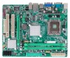
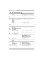
... 33 / 66 / 100 Bus Master Mode supports PIO Mode 0~4 SATA 2 Integrated Serial ATA Controller Data transfer rates up to RS-232 Port IDE Connector x1 Each connector supports 2 IDE device 2 Motherboard Manual 1.3 MOTHERBOARD FEATURES SPEC LGA 775 Supports Hyper-Threading / Execute Disable Bit / Intel Core2Duo / Core2Quad / Enhanced Intel SpeedStep® / Intel Architecture-64 / CPU Pentium Dual-Core / Celeron Dual-Core / Extended Memory 64 Technology / Virtualization Celeron 4xx processor Technology FSB Support 800 / 1066 / 1333 / 1600 MHz Chipset Intel G31 Intel ICH7 ITE...
... 33 / 66 / 100 Bus Master Mode supports PIO Mode 0~4 SATA 2 Integrated Serial ATA Controller Data transfer rates up to RS-232 Port IDE Connector x1 Each connector supports 2 IDE device 2 Motherboard Manual 1.3 MOTHERBOARD FEATURES SPEC LGA 775 Supports Hyper-Threading / Execute Disable Bit / Intel Core2Duo / Core2Quad / Enhanced Intel SpeedStep® / Intel Architecture-64 / CPU Pentium Dual-Core / Celeron Dual-Core / Extended Memory 64 Technology / Virtualization Celeron 4xx processor Technology FSB Support 800 / 1066 / 1333 / 1600 MHz Chipset Intel G31 Intel ICH7 ITE...
Setup Manual
Page 5
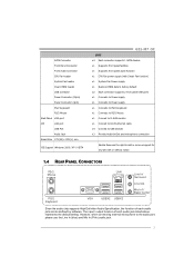
...to D-SUB monitor x1 Connect to RJ-45 ethernet cable x4 Connect to USB devices x3 Provide Audio-In/Out and microphone connection Biostar Reserves the right to the audio port, please use the Line In (blue) and Mic In (Pink) audio jack. 3 SATA Connector Front Panel Connector Front Audio Connector CPU Fan header System Fan header Clear CMOS header USB connector Power Connector (24pin) Power Connector (4pin) PS/2 Keyboard PS/2 Mouse Back Panel VGA port I/O LAN port USB Port Audio Jack Board Size 179 (W) x 235 (L) mm OS Support Windows 2000 / XP / VISTA G31-M7 OC SPEC x4 Each...
...to D-SUB monitor x1 Connect to RJ-45 ethernet cable x4 Connect to USB devices x3 Provide Audio-In/Out and microphone connection Biostar Reserves the right to the audio port, please use the Line In (blue) and Mic In (Pink) audio jack. 3 SATA Connector Front Panel Connector Front Audio Connector CPU Fan header System Fan header Clear CMOS header USB connector Power Connector (24pin) Power Connector (4pin) PS/2 Keyboard PS/2 Mouse Back Panel VGA port I/O LAN port USB Port Audio Jack Board Size 179 (W) x 235 (L) mm OS Support Windows 2000 / XP / VISTA G31-M7 OC SPEC x4 Each...
Setup Manual
Page 14
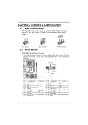
... 5 HDD LED (+) 6 HDD LED (-) 7 Ground 8 Reset control Function Pin 9 Speaker 10 Connector 11 12 Hard drive 13 LED 14 15 Reset button 16 Assignment N/A N/A N/A Power LED (+) Power LED (+) Power LED (-) Power button Ground Function N/A N/A Power LED Power-on , Reset, HDD LED, Power LED, and speaker connection. When the jumper cap is placed on pins, the jumper is "close", if not, that means the jumper is "open". It allows user to set up jumpers. Motherboard Manual CHAPTER 3: HEADERS & JUMPERS SETUP 3.1 HOW TO SETUP JUMPERS The illustration shows how to connect the PC case...
... 5 HDD LED (+) 6 HDD LED (-) 7 Ground 8 Reset control Function Pin 9 Speaker 10 Connector 11 12 Hard drive 13 LED 14 15 Reset button 16 Assignment N/A N/A N/A Power LED (+) Power LED (+) Power LED (-) Power button Ground Function N/A N/A Power LED Power-on , Reset, HDD LED, Power LED, and speaker connection. When the jumper cap is placed on pins, the jumper is "close", if not, that means the jumper is "open". It allows user to set up jumpers. Motherboard Manual CHAPTER 3: HEADERS & JUMPERS SETUP 3.1 HOW TO SETUP JUMPERS The illustration shows how to connect the PC case...
Setup Manual
Page 28
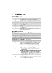
... are used for recovery 4 Flash Programming successful 5 File read error 7 No Flash EPROM detected 10 Flash Erase error 11 Flash Program error 12 "AMIBOOT.ROM" file size error 13 BIOS ROM image mismatch (file layout does not match image present in flash device) POST BIOS Beep Codes Number of Beeps Description 1 Memory refresh timer error 3 Base memory read/write test error 6 Keyboard controller BAT command failed 7 General exception error (processor exception interrupt error) 8 Display memory error (system video adapter) Troubleshooting POST BIOS Beep Codes Number...
... are used for recovery 4 Flash Programming successful 5 File read error 7 No Flash EPROM detected 10 Flash Erase error 11 Flash Program error 12 "AMIBOOT.ROM" file size error 13 BIOS ROM image mismatch (file layout does not match image present in flash device) POST BIOS Beep Codes Number of Beeps Description 1 Memory refresh timer error 3 Base memory read/write test error 6 Keyboard controller BAT command failed 7 General exception error (processor exception interrupt error) 8 Display memory error (system video adapter) Troubleshooting POST BIOS Beep Codes Number...


