Biostar G31-M7 Support Question
Biostar G31-M7 Support Question
Find answers below for this question about Biostar G31-M7.Need a Biostar G31-M7 manual? We have 2 online manuals for this item!
Question posted by physmcyclef on June 26th, 2014
Biostar G31 M7 Te Motherboard How To Overclock Cpu
The person who posted this question about this Biostar product did not include a detailed explanation. Please use the "Request More Information" button to the right if more details would help you to answer this question.
Requests for more information
Request from satyajitbajantrisb50 on March 11th, 2022 3:04 AM
please tell sir my pc showing this problem
please tell sir my pc showing this problem
Current Answers
Related Biostar G31-M7 Manual Pages
Bios Setup - Page 2
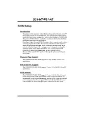
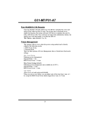
...from a disk. EPA Green PC Support
This PHOENIX-AWARD BIOS supports Version 1.03 of the Advanced Power Management (APM) specification. G31-M7/P31-A7
BIOS Setup
Introduction
The purpose of this manual is to CMOS RAM. The Setup program allows users to modify the ... are implemented via the System Management Interrupt (SMI). The power of CMOS RAM is supplied by this motherboard.
Bios Setup - Page 3
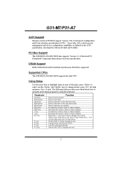
... Save all the CMOS changes and exit
2 Supported CPUs
This PHOENIX-AWARD BIOS supports the Intel CPU.
Keystroke
Up arrow Down arrow Left arrow Right arrow Move Enter PgUp key PgDn key + Key...
Quit and not save changes into CMOS Status Page Setup Menu and Option Page Setup Menu - G31-M7/P31-A7
ACPI Support
Phoenix-Award ACPI BIOS support Version 1.0b of the Intel PCI (Peripheral ...
Bios Setup - Page 5
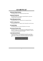
...factory settings optimized for this system.
Performance Booster Zone
This submenu allows you to change CPU Vcore Voltage and CPU/PCI clock. (However, we suggest you to configure certain IDE hard drive options and ...Peripherals
This submenu allows you to configure special chipset features. G31-M7/P31-A7
Advanced Chipset Features
This submenu allows you to configure certain "Plug and Play" and ...
Bios Setup - Page 12

Enabled (default) Enable cache. G31-M7/P31-A7
Cache Setup
CPU L3 Cache
Depending on the CPU/chipset in use, you may be able to increase memory access time with this option. Disabled Disable cache.
11
Bios Setup - Page 25
... when system wakes up from S3 state. Power Saving Minimum power management. The Choices: Auto (default), Yes, No. HDD Power Down = 1 min. except for sl CPU's. G31-M7/P31-A7
Run VGABIOS if S3 Resume
Choosing Enabled will need AGP driver to initialize the card. The system time is directly related to set...
Bios Setup - Page 30
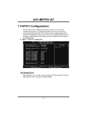
The Choices: PCIEx, Onboard, PCI Slot (default).
29 G31-M7/P31-A7
7 PnP/PCI Configurations
This section describes configuring the PCI bus system. This section covers some very technical items and ...Figure 7: PnP/PCI Configurations
Init Display First
This item allows you to decide to operate at speeds nearing the speed of the CPU itself uses when communicating with its own special components.
Bios Setup - Page 34

G31-M7/P31-A7
CPU Smart Fan
This item allows you to set value, FAN will turn off.
This item is only effective under Smart Fan Function mode. Smart Fan Calibration
PWM Duty Off
PWM Duty Start
CPU... Auto, 4-pin, 3-pin.. The Choices: Min=0,.Max=127, Key in a DEC number.
CPU Vcore, NB/SB Voltage, +3.3V, +5.0V, +12.0V, DDR Voltage, FSB Voltage, Voltage Battery
Detect the system...
Bios Setup - Page 35

Current CPU FAN Speed
This field displays the current speed of CPU. Current SYS FAN Speed
This field displays the current speed SYSTEM fan.
34 G31-M7/P31-A7
Current CPU Temperature
This field displays the current temperature of CPU fan.
Bios Setup - Page 36
..., +0.2V, +0.3V. The Choices: Default (default), +0.1V, +0.2V, +0.3V. Chipset Voltage
This item allows you to select memory Voltage Control.
G31-M7/P31-A7
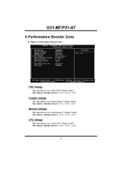
9 Performance Booster Zone
„ Figure 9: Performance Booster Zone
FSB Voltage
This item allows you to select CPU Voltage Control. CPU Voltage
This item allows you to select FSB Voltage Control.
Bios Setup - Page 37
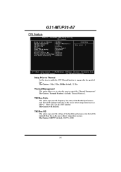
... when the on -die sensor detects temperature increase. The Choices: Thermal Monitor 1 (default), Thermal Monitor 2. The Choices: 4 Min, 8 Min, 16Min (default), 32 Min. G31-M7/P31-A7
CPU Feature
Delay Prior to Thermal
Set this item to enable the CPU Thermal function to control the "Thermal Management." The Choices: 0.8375V (default), 0.8375-1.6000.
36
Bios Setup - Page 38

... (default), Disabled. The Choices: Enabled (default), Disabled. CPU Clock Ratio Unlock
This item allows you to select the CPU Ratio. CPU Clock Ratio
This item allows you to select the CPU Ratio Unlock function. Min= 6 Max= 50, Key in a DEC number. The Choices: 6X (default).
37 G31-M7/P31-A7
PPM Mode
This item allows you...
Bios Setup - Page 39

... are two methods of booting-up the system according to FSB of the processor It's strongly recommended to select CPU Clock, and CPU over clocking.
This action will be loaded as "ON" status. G31-M7/P31-A7
PCIE Clock Select
The Choices: Fixed 100, Manual, Auto (default). Min= 200 Max= 600 Key in DEC...
Setup Manual - Page 3
CHAPTER 1: INTRODUCTION
G31-M7 OC
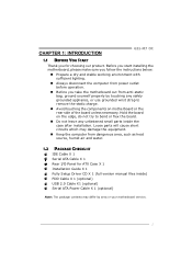
1.1 BEFORE YOU START
Thank you take the motherboard out from dangerous area, such as heat source, humid air and water.
1.2 PACKAGE CHECKLIST
...on the edge, do not try to remove the static charge.
„ Avoid touching the components on motherboard or the rear side of the board unless necessary. Loose parts will cause short circuits which may differ by...
Setup Manual - Page 5
... mm
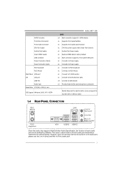
OS Support Windows 2000 / XP / VISTA
G31-M7 OC
SPEC x4 Each connector supports 1 SATA devices x1 Supports front panel facilities x1 Supports front panel audio function x1 CPU Fan power supply (with Smart Fan function) x1 ... Connect to USB devices x3 Provide Audio-In/Out and microphone connection
Biostar Reserves the right to the audio port, please use the Line In (blue) and Mic In (Pink)...
Setup Manual - Page 7
....
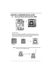
5 Pin-Cap Step 1: Pull the socket locking lever out from the socket and then raise the lever up to ensure pin legs won't be damaged.
G31-M7 OC
CHAPTER 2: HARDWARE INSTALLATION 2.1 INSTALLING CENTRAL PROCESSING UNIT (CPU)
Special Notice: Remove Pin Cap before installation, and make good preservation for future use.
Setup Manual - Page 9

... connector while matching the black wire to GND.
7 The fan cable and connector may be connected to pin#1. G31-M7 OC
2.2 FAN HEADERS
These fan headers support cooling-fans built in the computer.
JCFAN1: CPU Fan Header
4
1 Pin Assignment 1 Ground 2 Power 3 FAN RPM rate sense 4 Smart Fan Control
JSFAN1: System Fan Header
13...
Setup Manual - Page 11
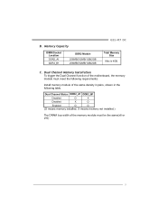
B. C. Dual Channel Memory Installation To trigger the Dual Channel function of the motherboard, the memory module must be the same(x8 or x16)
9
Dual Channel Status DDR2_A1 DDR2_B1
Disabled
O
X
Disabled
X
O
Enabled
O
O
(O means ....
Memory Capacity
DIMM Socket Location
DDR2_A1 DDR2_B1
DDR2 Module
256MB/512MB/1GB/2GB 256MB/512MB/1GB/2GB
G31-M7 OC
Total Memory Size
Max is 4GB.
Setup Manual - Page 13
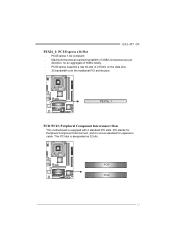
G31-M7 OC PEX16_1: PCI-Express x16 Slot - PCI1 PCI2
11 Maximum theoretical realized bandwidth of 4GB/s simultaneously per
direction, ... data pins. - 2X bandwidth over the traditional PCI architecture. PEX16_1
PCI1/PCI2: Peripheral Component Interconnect Slots
This motherboard is designated as 32 bits. This PCI slot is equipped with 2 standard PCI slots.
PCI-Express 1.0a compliant. -
Setup Manual - Page 15

G31-M7 OC
JATXPWR1: ATX Power Source Connector
This connector allows user to connect 24-pin power connector on the ...9
Standby Voltage+5V
10
+12V
11
+12V
12
+3.3V
JATXPWR2: ATX Power Source Connector
By connecting this connector, it will provide +12V to CPU power circuit.
14
23
Pin Assignment
1
+12V
2
+12V
3
Ground
4
Ground
Note: Before power on the system, please make sure that ...
Setup Manual - Page 17

...close ". 5. Set the jumper to "Pin 1-2 close ". 3. Remove AC power line. 2. SATA1~SATA4: Serial ATA Connectors
The motherboard has a PCI to avoid damaging the motherboard.
3
1
Pin 1-2 Close: Normal Operation (Default).
3
1 3
1
Pin 2-3 Close: Clear CMOS data.
※ Clear CMOS... or clear the CMOS data.
G31-M7 OC
JCMOS1: Clear CMOS Header
By placing the jumper on the AC. 6.
Similar Questions

Display Fades While Booting And Screen Becomes Dark. Motherboard P4m890-m7 Te
(Posted by shamnaarai 2 years ago)

8gb Ram On Motherboard G31 M7 V 6.5 Te
is there any way I can instal 8GB RAM on motherboard G31 M7 v 6.5 TE?
is there any way I can instal 8GB RAM on motherboard G31 M7 v 6.5 TE?
(Posted by placewithspace 10 years ago)

Help Me Driverbiostar P4m890-m7 Te.v 7.1
help me driver biostar p4m89-m7 te v 7.1
help me driver biostar p4m89-m7 te v 7.1
(Posted by anwarcell147 10 years ago)

How Can Fix This Motherboard Back Pannel Ps/2 And Usb Doesn't Worked?
back pannel vga port, lan port, and sound ports is working but ps/2, and usb port not working?
back pannel vga port, lan port, and sound ports is working but ps/2, and usb port not working?
(Posted by dnttell 11 years ago)