Biostar G31-M7 Support Question
Biostar G31-M7 Support Question
Find answers below for this question about Biostar G31-M7.Need a Biostar G31-M7 manual? We have 2 online manuals for this item!
Question posted by dnttell on April 1st, 2013
How Can Fix This Motherboard Back Pannel Ps/2 And Usb Doesn't Worked?
back pannel vga port, lan port, and sound ports is working but ps/2, and usb port not working?
Current Answers
Related Biostar G31-M7 Manual Pages
Bios Setup - Page 2
G31-M7/P31-A7
BIOS Setup
...on this PHOENIX-AWARD BIOS.
1 Some additional features, such as keyboard, mouse, serial ports and disk drives.
The rest of the booting process, loading and executing the operating system....Setup. Power to CMOS RAM. The power of CMOS RAM is supplied by this motherboard. Plug and Play Support
This PHOENIX-AWARD BIOS supports the Plug and Play Version 1....
Bios Setup - Page 13

The Choices: Pri. Master, Pri. Slave, USB HDD0, USB HDD1, USB HDD2 and Bootable Add-in Cards.
12 Slave, Sec. Hard Disk Boot Priority The BIOS will attempt to setup boot sequence & Floppy. Master, Sec.
G31-M7/P31-A7
Boot Seq & Floppy Setup
This item allows you to arrange the Hard Disk boot sequence automatically.You can change the Hard Disk booting sequence here.
Bios Setup - Page 14

... Seek
When enabled, System will test the floppy drives to boot-up . Disabling this order. G31-M7/P31-A7
First/Second/Third Boot Device
The BIOS will attempt to swap logical drive assignments. The... during boot up . The Choices: Floppy, LS120, Hard Disk, CDROM, ZIP100, USB-FDD, USB-ZIP, USB-CDROM, Legacy LAN, Disabled. Boot Other Device
When enabled, BIOS will try to load the operating system...
Bios Setup - Page 16

... Mode
This item allows you to select the UVMT mode.
The Choice: DVMT (default), FIXED.
15 Disabled (default) PCI Express X16 Enabled PCI Express X1
On-Chip Frame Buffer Size...Onchip VGA Control
This item allows you to enable or disable PEG/On-chip VGA controller. PEG Force X1
When using on-chip VGA, this frame buffer size will be fixed. G31-M7/P31-A7
PCI Express Root Port Func...
Bios Setup - Page 17

... memory architecture (UMA) concept. DVMT dynamically respond to be allocated for „Dynamic Video Memory Technology". The Choices: 128MB (default), 256MB, MAX.
16 G31-M7/P31-A7
DVMT/FIXED Memory Size
DVMT stands for a balance between graphics and system performance. This is an enhancement of display, texturing and buffer memory after the operating...
Bios Setup - Page 22

... speed device were attached. EPP Using Parallel Port as Standard Printer Port. The default value is to determine how the parallel port should function. USB Device Setting
USB 1.0/2.0 Controller
This entry is SPP. The Choices: 3 (default), 1. The Choices: SPP (default) Using Parallel port as Enhanced Parallel Port. G31-M7/P31-A7
Parallel Port Mode
This item allows you to enabled...
Bios Setup - Page 23

G31-M7/P31-A7
USB Operation Mode
Auto decide USB device operation mode. [High speed]: if USB device was full/low speed device, then it operated on FUUL/LOW speed mode. If USB device was high speed device, then it operated on full/low speed mode. [Full/Low Speed]: All OF USB device operated on high speed mode...
Bios Setup - Page 25
... the function, but system will make BIOS run VGA BIOS to initialize the VGA card when system wakes up from 1 min....fixed mode settings Min. User Define Allow you can adjust each option individually. HDD Power Down. 2. When you choose user define, you to set each of the VGA card does not support the initialization feature, the display may work abnormally or not function after S3. G31-M7...
Bios Setup - Page 27

G31-M7/P31-A7
Soft-Off by PBTN
This item determines the behavior of system resume. will work.
26 When enabled, you to press and hold the power button for...boot up.
The Choices: Disabled (default), Enabled. The Choices: Enabled, Disabled (default). Instant off turn off state.
USB KB/MS Wake-Up From S3
This item allows you select "Enable", a PME signal from PCI card returns the ...
Bios Setup - Page 39

... CPU or M/B damage.
38
All the CMOS data will boot-up the system. This action will be loaded as "ON" status. G31-M7/P31-A7
PCIE Clock Select
The Choices: Fixed 100, Manual, Auto (default). Special Notice: If the system's frequency that keep-on pressing the key until the power-on screen showed...
Setup Manual - Page 2
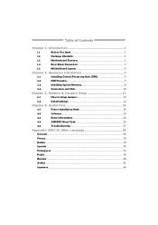
Table of Contents
Chapter 1: Introduction 1
1.1
Before You Start 1
1.2
Package Checklist 1
1.3
Motherboard Features 2
1.4
Rear Panel Connectors 3
1.5
Motherboard Layout 4
Chapter 2: Hardware Installation 5
2.1
Installing Central Processing Unit (CPU 5
2.2
FAN Headers 7
2.3
Installing System Memory 8
2.4
Connectors and Slots 10
Chapter 3: Headers & Jumpers Setup 12...
Setup Manual - Page 3
... small parts inside ) FDD Cable X 1 (optional) USB 2.0 Cable X1 (optional) Serial ATA Power Cable X ...G31-M7 OC
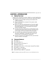
1.1 BEFORE YOU START
Thank you take the motherboard out from anti-static bag, ground yourself properly by area or your motherboard version.
1 Before you start installing the motherboard, please make sure you follow the instructions below:
„ Prepare a dry and stable working...
Setup Manual - Page 4
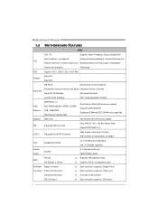
... / 1066 / 1333 / 1600 MHz
Chipset
Intel G31 Intel ICH7
ITE 8712F
Environment Control initiatives,
Super I/O
Provides the most commonly used legacy Hardware Monitor Controller
Super I/O functionality.
SATA Version 2.0 specification compliant
LAN
Realtek RTL 8102EL
10 / 100 Mb/s auto negotiation Half / Full duplex capability
Sound Codec
ALC662
5.1 channels audio out High Definition...
Setup Manual - Page 5
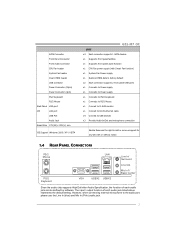
... Connector
Front Audio Connector
CPU Fan header
System Fan header
Clear CMOS header
USB connector
Power Connector (24pin)
Power Connector (4pin)
PS/2 Keyboard
PS/2 Mouse
Back Panel VGA port
I/O
LAN port
USB Port
Audio Jack
Board Size 179 (W) x 235 (L) mm
OS Support Windows 2000 / XP / VISTA
G31-M7 OC
SPEC x4 Each connector supports 1 SATA devices x1 Supports front panel facilities...
Setup Manual - Page 6

SATA4 SATA3
4 Motherboard Manual
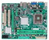
1.5 MOTHERBOARD LAYOUT
JKBMS1 JATXPWR2
LGA775
CPU1
JCFAN1 JATXPWR1
DDR2_A1 DDR2_B1
JVGA1
JUSBV1 JUSB2
JRJ45USB1
I nt el G31
IDE1
JAUDIO1
BIOS
JAUDIOF1
LAN
BATTERY PEX16_1
Super I/O
Codec
PCI1
JPRNT1
PCI2
JCOM2
Intel ICH7
JUSB3
FDD1
JSFAN1
JUSB4
JPANEL1 JCMOS1 SATA1 SATA2
Note: ■ represents the 1st pin.
Setup Manual - Page 8

Connect the CPU FAN power cable into the JCFAN1. This completes the installation.
6 Motherboard Manual Step 2: Look for the triangular cut edge.
Step 2-1:
Step 2-2:
Step 3: Hold the CPU down firmly, and then lower the lever to locked position to ...
Setup Manual - Page 10
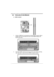
Align a DIMM on the slot such that the notch on the DIMM matches the break on the Slot.
2. Unlock a DIMM slot by pressing the retaining clips outward. Insert the DIMM vertically and firmly into the slot until the retaining chip snap back in place and the DIMM is properly seated.
8 DDR2_A 1 DDR2_B 1
Motherboard Manual
2.3 INSTALLING SYSTEM MEMORY
A. DDR2 module
1.
Setup Manual - Page 16

...
JUSB3/JUSB4: Headers for USB 2.0 Ports at Front Panel
This motherboard provides 2 USB 2.0 headers, which allows user to connect the front audio output cable with internal USB devices, like USB card reader. JUSB3 JUSB4
2
10
1
9
Pin Assignment 1 +5V (fused) 2 +5V (fused) 3 USB4 USB5 USB+ 6 USB+ 7 Ground 8 Ground 9 Key 10 NC
JAUDIOF1: Front Panel Audio Header
This header allows...
Setup Manual - Page 18

...-232 Port.
2
10
1
9
Pin Assignment 1 Carrier detect 2 Received data 3 Transmitted data 4 Data terminal ready 5 Signal ground 6 Data set ready 7 Request to send 8 Clear to send 9 Ring indicator 10 Key
16 Pin 2-3 Close: +5V STB for USB ports at JUSB2/JRJ45USB1.
3 1
3 1 Pin 1-2 close
3 1 Pin 2-3 close
JCOM2: Serial port Connector
The motherboard has a Serial Port Connector for USB ports at...
Setup Manual - Page 27
... lead to reboot the system. Then, save the BIOS file into a USB pen drive or a floppy disk. 3. z Shutting down or resetting the system while updating the BIOS will ask you an easy and simple way to enter the utility.
5. G31-M7 OC
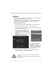
BIO-Flasher
BIO-Flasher is built in the BIOS chip. z This...
Similar Questions

Display Fades While Booting And Screen Becomes Dark. Motherboard P4m890-m7 Te
(Posted by shamnaarai 2 years ago)

8gb Ram On Motherboard G31 M7 V 6.5 Te
is there any way I can instal 8GB RAM on motherboard G31 M7 v 6.5 TE?
is there any way I can instal 8GB RAM on motherboard G31 M7 v 6.5 TE?
(Posted by placewithspace 10 years ago)

I Have Biostar G-41 M 7x6
Running Win 7x64.
Only Two Usb Ports Working Same Ti
Only two USB working at same time, I can swith USB mouse and Keyboard betwin all 4 and they are work...
Only two USB working at same time, I can swith USB mouse and Keyboard betwin all 4 and they are work...
(Posted by LMstudio 10 years ago)
Download Audio Installers For Motherboard G31d-m7 Ver 8.2
(Posted by luctktlt 10 years ago)