
Setup Manual
Page 1
... merchantability or fitness for any mistakes found to comply with the instructions, may cause harmful interference to radio communications. The content of their respective companies. G31-M7 OC Setup Manual FCC Information and Copyright This equipment has been tested and found in this user's manual is subject to be responsible for any purpose...
... merchantability or fitness for any mistakes found to comply with the instructions, may cause harmful interference to radio communications. The content of their respective companies. G31-M7 OC Setup Manual FCC Information and Copyright This equipment has been tested and found in this user's manual is subject to be responsible for any purpose...
Setup Manual
Page 3
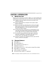
..., ground yourself properly by area or your motherboard version. 1 Hold the board on motherboard or the rear side of the board unless necessary. CHAPTER 1: INTRODUCTION G31-M7 OC 1.1 BEFORE YOU START Thank you take the motherboard out from dangerous area, such as heat source, humid air and water. 1.2 PACKAGE CHECKLIST IDE Cable X 1 Serial...
..., ground yourself properly by area or your motherboard version. 1 Hold the board on motherboard or the rear side of the board unless necessary. CHAPTER 1: INTRODUCTION G31-M7 OC 1.1 BEFORE YOU START Thank you take the motherboard out from dangerous area, such as heat source, humid air and water. 1.2 PACKAGE CHECKLIST IDE Cable X 1 Serial...
Setup Manual
Page 5
... Keyboard PS/2 Mouse Back Panel VGA port I/O LAN port USB Port Audio Jack Board Size 179 (W) x 235 (L) mm OS Support Windows 2000 / XP / VISTA G31-M7 OC SPEC x4 Each connector supports 1 SATA devices x1 Supports front panel facilities x1 Supports front panel audio function x1 CPU Fan power supply (with Smart... x1 Connect to D-SUB monitor x1 Connect to RJ-45 ethernet cable x4 Connect to USB devices x3 Provide Audio-In/Out and microphone connection Biostar Reserves the right to the audio port, please use the Line In (blue) and Mic In (Pink) audio jack. 3 The input / output function...
... Keyboard PS/2 Mouse Back Panel VGA port I/O LAN port USB Port Audio Jack Board Size 179 (W) x 235 (L) mm OS Support Windows 2000 / XP / VISTA G31-M7 OC SPEC x4 Each connector supports 1 SATA devices x1 Supports front panel facilities x1 Supports front panel audio function x1 CPU Fan power supply (with Smart... x1 Connect to D-SUB monitor x1 Connect to RJ-45 ethernet cable x4 Connect to USB devices x3 Provide Audio-In/Out and microphone connection Biostar Reserves the right to the audio port, please use the Line In (blue) and Mic In (Pink) audio jack. 3 The input / output function...
Setup Manual
Page 7
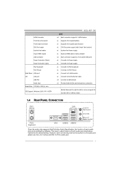
Pin-Cap Step 1: Pull the socket locking lever out from the socket and then raise the lever up to ensure pin legs won't be damaged. G31-M7 OC CHAPTER 2: HARDWARE INSTALLATION 2.1 INSTALLING CENTRAL PROCESSING UNIT (CPU) Special Notice: Remove Pin Cap before installation, and make good preservation for future use. When the CPU is removed, cover the Pin Cap on the empty socket to a 90-degree angle. 5
Pin-Cap Step 1: Pull the socket locking lever out from the socket and then raise the lever up to ensure pin legs won't be damaged. G31-M7 OC CHAPTER 2: HARDWARE INSTALLATION 2.1 INSTALLING CENTRAL PROCESSING UNIT (CPU) Special Notice: Remove Pin Cap before installation, and make good preservation for future use. When the CPU is removed, cover the Pin Cap on the empty socket to a 90-degree angle. 5

Setup Manual
Page 9
... the red wire is the positive and should be connected to pin#2, and the black wire is Ground and should be different according to GND. 7 G31-M7 OC 2.2 FAN HEADERS These fan headers support cooling-fans built in the computer. The fan cable and connector may be connected to the fan manufacturer. Connect...
... the red wire is the positive and should be connected to pin#2, and the black wire is Ground and should be different according to GND. 7 G31-M7 OC 2.2 FAN HEADERS These fan headers support cooling-fans built in the computer. The fan cable and connector may be connected to the fan manufacturer. Connect...
Setup Manual
Page 11
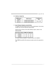
Memory Capacity DIMM Socket Location DDR2_A1 DDR2_B1 DDR2 Module 256MB/512MB/1GB/2GB 256MB/512MB/1GB/2GB G31-M7 OC Total Memory Size Max is 4GB. Dual Channel Memory Installation To trigger the Dual Channel function of the same density in pairs, shown in the ...
Memory Capacity DIMM Socket Location DDR2_A1 DDR2_B1 DDR2 Module 256MB/512MB/1GB/2GB 256MB/512MB/1GB/2GB G31-M7 OC Total Memory Size Max is 4GB. Dual Channel Memory Installation To trigger the Dual Channel function of the same density in pairs, shown in the ...
Setup Manual
Page 13
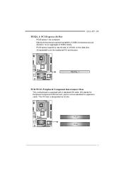
PCI-Express 1.0a compliant. - PCI-Express supports a raw bit-rate of 8GB/s totally. - PEX16_1 PCI1/PCI2: Peripheral Component Interconnect Slots This motherboard is designated as 32 bits. PCI1 PCI2 11 Maximum theoretical realized bandwidth of 4GB/s simultaneously per direction, for expansion cards. This PCI slot is equipped with 2 standard PCI slots. PCI stands for Peripheral Component Interconnect, and it is a bus standard for an aggregate of 2.5Gb/s on the data pins. - 2X bandwidth over the traditional PCI architecture. G31-M7 OC PEX16_1: PCI-Express x16 Slot -
PCI-Express 1.0a compliant. - PCI-Express supports a raw bit-rate of 8GB/s totally. - PEX16_1 PCI1/PCI2: Peripheral Component Interconnect Slots This motherboard is designated as 32 bits. PCI1 PCI2 11 Maximum theoretical realized bandwidth of 4GB/s simultaneously per direction, for expansion cards. This PCI slot is equipped with 2 standard PCI slots. PCI stands for Peripheral Component Interconnect, and it is a bus standard for an aggregate of 2.5Gb/s on the data pins. - 2X bandwidth over the traditional PCI architecture. G31-M7 OC PEX16_1: PCI-Express x16 Slot -

Setup Manual
Page 15
G31-M7 OC JATXPWR1: ATX Power Source Connector This connector allows user to connect 24-pin power connector on the ATX power supply. 12 24 1 13 Pin Assignment ...
G31-M7 OC JATXPWR1: ATX Power Source Connector This connector allows user to connect 24-pin power connector on the ATX power supply. 12 24 1 13 Pin Assignment ...

Setup Manual
Page 17
... (Default). 3 1 3 1 Pin 2-3 Close: Clear CMOS data. ※ Clear CMOS Procedures: 1. SATA4 SATA3 SATA1 SATA2 Pin Assignment 1 Ground 2 TX+ 3 TX4 Ground 5 RX6 RX+ 7 Ground 7 41 15 G31-M7 OC JCMOS1: Clear CMOS Header By placing the jumper on the AC. 6. Wait for five seconds. 4.
... (Default). 3 1 3 1 Pin 2-3 Close: Clear CMOS data. ※ Clear CMOS Procedures: 1. SATA4 SATA3 SATA1 SATA2 Pin Assignment 1 Ground 2 TX+ 3 TX4 Ground 5 RX6 RX+ 7 Ground 7 41 15 G31-M7 OC JCMOS1: Clear CMOS Header By placing the jumper on the AC. 6. Wait for five seconds. 4.

Setup Manual
Page 19
G31-M7 OC 2 1 Pin Assignment 1 -Strobe 2 -ALF 3 Data 0 4 -Error 5 Data 1 6 -Init 7 Data 2 8 -Scltin 9 Data 3 10 Ground 11 Data 4 12 Ground 13 Data 5 25 Pin Assignment 14 Ground 15 Data 6 16 Ground 17 Data 7 18 Ground 19 -ACK 20 Ground 21 Busy 22 Ground 23 PE 24 Ground 25 SCLT 26 Key 17 JPRNT1: Printer Port Connector This header allows you to connector printer on the PC.
G31-M7 OC 2 1 Pin Assignment 1 -Strobe 2 -ALF 3 Data 0 4 -Error 5 Data 1 6 -Init 7 Data 2 8 -Scltin 9 Data 3 10 Ground 11 Data 4 12 Ground 13 Data 5 25 Pin Assignment 14 Ground 15 Data 6 16 Ground 17 Data 7 18 Ground 19 -ACK 20 Ground 21 Busy 22 Ground 23 PE 24 Ground 25 SCLT 26 Key 17 JPRNT1: Printer Port Connector This header allows you to connector printer on the PC.
Setup Manual
Page 21
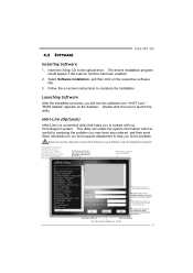
... on that helps you to help you must provide. Save these information to our tech-support department to contact with our Tech-Support system. 4.2 SOFTWARE G31-M7 OC Installing Software 1. eHot-Line (Optional) eHot-Line is useful for analyzing the problem you may not be collected in forma tion to launch the utility...
... on that helps you to help you must provide. Save these information to our tech-support department to contact with our Tech-Support system. 4.2 SOFTWARE G31-M7 OC Installing Software 1. eHot-Line (Optional) eHot-Line is useful for analyzing the problem you may not be collected in forma tion to launch the utility...
Setup Manual
Page 23
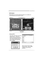
... for AMI BIOS) Save current BIOS to a .bin file Update BIOS with a BIOS file Once click on OK to complete the BIOS Backup procedure. 21 G31-M7 OC BIOS Update BIOS Update is a convenient utility which allows you to save file and enter file name. (We recommend that the file name should be...
... for AMI BIOS) Save current BIOS to a .bin file Update BIOS with a BIOS file Once click on OK to complete the BIOS Backup procedure. 21 G31-M7 OC BIOS Update BIOS Update is a convenient utility which allows you to save file and enter file name. (We recommend that the file name should be...

Setup Manual
Page 25
... procedure may be changed without notice. While the system boots up and the full screen logo shows, press key to be slightly different from internet. G31-M7 OC (for the latest BIOS from this function. If there is a new BIOS version, the utility will ask you to reboot the system. All the information...
... procedure may be changed without notice. While the system boots up and the full screen logo shows, press key to be slightly different from internet. G31-M7 OC (for the latest BIOS from this function. If there is a new BIOS version, the utility will ask you to reboot the system. All the information...
Setup Manual
Page 27
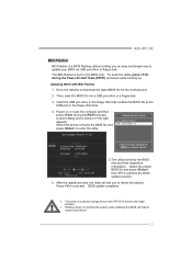
... partition. A select dialog as the picture on or reset the computer and then press during the Power-On Self Tests (POST) procedure while booting up. G31-M7 OC BIO-Flasher BIO-Flasher is built in the BIOS chip. Then, save the BIOS file into a USB pen drive or a floppy disk. 3. After the update...
... partition. A select dialog as the picture on or reset the computer and then press during the Power-On Self Tests (POST) procedure while booting up. G31-M7 OC BIO-Flasher BIO-Flasher is built in the BIOS chip. Then, save the BIOS file into a USB pen drive or a floppy disk. 3. After the update...

Setup Manual
Page 29
... setup. Call the drive manufacturers for compatibility with other drives. 27 No power to disk controller board. Review system's equipment. Set master/slave jumpers correctly. 2. G31-M7 OC 4.5 TROUBLESHOOTING Probable Solution 1. Make sure power cable is impossible. Indicator light on . System inoperative. Using even pressure on . 3. Check cable running from hard disk 2. Make...
... setup. Call the drive manufacturers for compatibility with other drives. 27 No power to disk controller board. Review system's equipment. Set master/slave jumpers correctly. 2. G31-M7 OC 4.5 TROUBLESHOOTING Probable Solution 1. Make sure power cable is impossible. Indicator light on . System inoperative. Using even pressure on . 3. Check cable running from hard disk 2. Make...