Setup Manual
Page 4
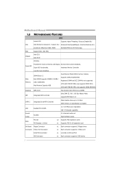
... Bus Master Mode supports PIO Mode 0~4 SATA 2 Integrated Serial ATA Controller Data transfer rates up to RS-232 Port IDE Connector x1 Each connector supports 2 IDE device 2 Motherboard Manual 1.3 MOTHERBOARD FEATURES SPEC Socket 478 Supports Hyper-Threading / Execute Disable Bit / CPU Intel Pentium4 /Celeron D / Celeron 3xx Enhanced Intel SpeedStep® / Intel Architecture-64 / processors (Maximum Watt: 95W) Extended Memory 64 Technology FSB Support 800 / 533 MHz Chipset Intel G31 Intel ICH7 ITE 8721 Super I/O Provides the most commonly used legacy Environment Control...
... Bus Master Mode supports PIO Mode 0~4 SATA 2 Integrated Serial ATA Controller Data transfer rates up to RS-232 Port IDE Connector x1 Each connector supports 2 IDE device 2 Motherboard Manual 1.3 MOTHERBOARD FEATURES SPEC Socket 478 Supports Hyper-Threading / Execute Disable Bit / CPU Intel Pentium4 /Celeron D / Celeron 3xx Enhanced Intel SpeedStep® / Intel Architecture-64 / processors (Maximum Watt: 95W) Extended Memory 64 Technology FSB Support 800 / 533 MHz Chipset Intel G31 Intel ICH7 ITE 8721 Super I/O Provides the most commonly used legacy Environment Control...
Setup Manual
Page 5
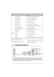
... supports High Definition Audio Specification, the function of each audio jack can be defined by software. SATA Connector Front Panel Connector Front Audio Connector CPU Fan Header System Fan Header Clear CMOS Header USB Connector Power Connector (24pin) Power Connector (4pin) PS/2 Keyboard PS/2 Mouse Back Panel VGA port I/O LAN port USB Port Audio Jack Board Size 200 (W) x 235 (L) mm OS Support Windows 2000 / XP / Vista / 7 G31-M4 SPEC x4 Each connector supports 1 SATA devices x1 Supports front panel facilities x1 Supports front panel audio function x1 CPU Fan power supply...
... supports High Definition Audio Specification, the function of each audio jack can be defined by software. SATA Connector Front Panel Connector Front Audio Connector CPU Fan Header System Fan Header Clear CMOS Header USB Connector Power Connector (24pin) Power Connector (4pin) PS/2 Keyboard PS/2 Mouse Back Panel VGA port I/O LAN port USB Port Audio Jack Board Size 200 (W) x 235 (L) mm OS Support Windows 2000 / XP / Vista / 7 G31-M4 SPEC x4 Each connector supports 1 SATA devices x1 Supports front panel facilities x1 Supports front panel audio function x1 CPU Fan power supply...
Setup Manual
Page 14
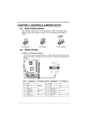
... on , Reset, HDD LED, Power LED, and speaker connection. Motherboard Manual CHAPTER 3: HEADERS & JUMPERS SETUP 3.1 HOW TO SETUP JUMPERS The illustration shows how to connect the PC case's front panel switch functions. - When the jumper cap is "open". PWR_LED On/Off 9 ++ 16 1 + 8 SPK R ST H LED Pin Assignment 1 +5V 2 N/A 3 N/A 4 Speaker 5 HDD LED (+) 6 HDD LED (-) 7 Ground 8 Reset control Function Pin 9 Speaker 10 Connector 11 12 Hard drive 13 LED 14 15 Reset button 16 Assignment N/A N/A N/A Power LED (+) Power LED (+) Power LED (-) Power button Ground...
... on , Reset, HDD LED, Power LED, and speaker connection. Motherboard Manual CHAPTER 3: HEADERS & JUMPERS SETUP 3.1 HOW TO SETUP JUMPERS The illustration shows how to connect the PC case's front panel switch functions. - When the jumper cap is "open". PWR_LED On/Off 9 ++ 16 1 + 8 SPK R ST H LED Pin Assignment 1 +5V 2 N/A 3 N/A 4 Speaker 5 HDD LED (+) 6 HDD LED (-) 7 Ground 8 Reset control Function Pin 9 Speaker 10 Connector 11 12 Hard drive 13 LED 14 15 Reset button 16 Assignment N/A N/A N/A Power LED (+) Power LED (+) Power LED (-) Power button Ground...
Setup Manual
Page 24
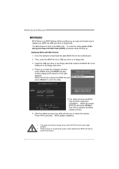
... during the Power-On Self Tests (POST) procedure while booting up. Motherboard Manual BIO-Flasher BIO-Flasher is built in the BIOS chip. Go to the website to enter the utility. 5. z Shutting down or resetting the system while updating the BIOS will ask you an easy and simple way to system boot failure. 22 Then, save the BIOS file into a USB pen drive or a floppy disk. 3. The utility will show the BIOS files and their...
... during the Power-On Self Tests (POST) procedure while booting up. Motherboard Manual BIO-Flasher BIO-Flasher is built in the BIOS chip. Go to the website to enter the utility. 5. z Shutting down or resetting the system while updating the BIOS will ask you an easy and simple way to system boot failure. 22 Then, save the BIOS file into a USB pen drive or a floppy disk. 3. The utility will show the BIOS files and their...
Setup Manual
Page 25
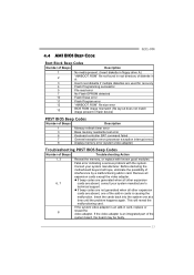
... are used for recovery 4 Flash Programming successful 5 File read error 7 No Flash EPROM detected 10 Flash Erase error 11 Flash Program error 12 "AMIBOOT.ROM" file size error 13 BIOS ROM image mismatch (file layout does not match image present in flash device) POST BIOS Beep Codes Number of Beeps Description 1 Memory refresh timer error 3 Base memory read/write test error 6 Keyboard controller BAT command failed 7 General exception error (processor exception interrupt error) 8 Display memory error (system video adapter) Troubleshooting POST BIOS Beep Codes Number...
... are used for recovery 4 Flash Programming successful 5 File read error 7 No Flash EPROM detected 10 Flash Erase error 11 Flash Program error 12 "AMIBOOT.ROM" file size error 13 BIOS ROM image mismatch (file layout does not match image present in flash device) POST BIOS Beep Codes Number of Beeps Description 1 Memory refresh timer error 3 Base memory read/write test error 6 Keyboard controller BAT command failed 7 General exception error (processor exception interrupt error) 8 Display memory error (system video adapter) Troubleshooting POST BIOS Beep Codes Number...
Bios Setup
Page 2
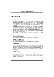
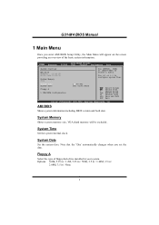
... operating system. Sleep and Suspend power management modes are implemented via the System Management Interrupt (SMI). This system controls most of Advanced Configuration and Power interface specification (ACPI). Plug and Play Support This AMI BIOS supports the Plug and Play Version 1.0A specification. ACPI Support AMI ACPI BIOS support Version 1.0/2.0 of the input and output devices such as keyboard, mouse, serial ports and disk drives. The power of the Advanced Power Management (APM) specification. APM Support This AMI BIOS supports Version 1.1&1.2 of CMOS RAM is turned off.
... operating system. Sleep and Suspend power management modes are implemented via the System Management Interrupt (SMI). This system controls most of Advanced Configuration and Power interface specification (ACPI). Plug and Play Support This AMI BIOS supports the Plug and Play Version 1.0A specification. ACPI Support AMI ACPI BIOS support Version 1.0/2.0 of the input and output devices such as keyboard, mouse, serial ports and disk drives. The power of the Advanced Power Management (APM) specification. APM Support This AMI BIOS supports Version 1.1&1.2 of CMOS RAM is turned off.
Bios Setup
Page 3
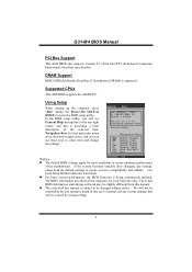
G31-M4 BIOS Manual PCI Bus Support This AMI BIOS also supports Version 2.3 of the motherboard. DRAM Support DDR2 SDRAM (Double Data Rate II Synchronous DRAM) is being continuously updated. Using Setup When starting up the computer, press during the Power-On Self-Test (POST) to ensure system's compatibility and stability. General Help Navigation Keys Notice z The default BIOS settings apply for most conditions to ensure optimum performance of the Intel PCI (Peripheral Component Interconnect) local bus specification. z For...
G31-M4 BIOS Manual PCI Bus Support This AMI BIOS also supports Version 2.3 of the motherboard. DRAM Support DDR2 SDRAM (Double Data Rate II Synchronous DRAM) is being continuously updated. Using Setup When starting up the computer, press during the Power-On Self-Test (POST) to ensure system's compatibility and stability. General Help Navigation Keys Notice z The default BIOS settings apply for most conditions to ensure optimum performance of the Intel PCI (Peripheral Component Interconnect) local bus specification. z For...
Bios Setup
Page 4
System Time Set the system internal clock. System Date Set the system date. Note that the 'Day' automatically changes when you enter AMI BIOS Setup Utility, the Main Menu will be excluded.. System Time System Date Floppy A > IDE/SATA Configuration [00:00:00] [Fri 01/01/2010] Select Screen Select Item +- G31-M4 BIOS Manual 1 Main Menu Once you set the date. Use [+] or [-] to select a field. Change Field Tab Select Field F1 General Help F10...
System Time Set the system internal clock. System Date Set the system date. Note that the 'Day' automatically changes when you enter AMI BIOS Setup Utility, the Main Menu will be excluded.. System Time System Date Floppy A > IDE/SATA Configuration [00:00:00] [Fri 01/01/2010] Select Screen Select Item +- G31-M4 BIOS Manual 1 Main Menu Once you set the date. Use [+] or [-] to select a field. Change Field Tab Select Field F1 General Help F10...
Bios Setup
Page 5
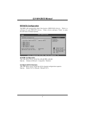
... (Default) / Compatible / Disabled Configure SATA Channels This item allows you to control the SATA channel configuration sequence. Options: Before PATA (Default) / Behind PATA 4 Main IDE/SATA Confuguration ATA/IDE Configuration Configure SATA Channels > SATA1 Device > SATA2 Device > SATA3 Device > SATA4 Device > IDE Channel 1 Master > IDE Channel 1 Slave Hard Disk Write Protect IDE Detect Time Out (Sec) BIOS SETUP UTILITY [Enhanced] [Before PATA] [Disabled] [35] Options Disabled Compatible Enhanced Select Screen Select Item EnterGo to enter the sub-menu of IDE/SATA devices.
... (Default) / Compatible / Disabled Configure SATA Channels This item allows you to control the SATA channel configuration sequence. Options: Before PATA (Default) / Behind PATA 4 Main IDE/SATA Confuguration ATA/IDE Configuration Configure SATA Channels > SATA1 Device > SATA2 Device > SATA3 Device > SATA4 Device > IDE Channel 1 Master > IDE Channel 1 Slave Hard Disk Write Protect IDE Detect Time Out (Sec) BIOS SETUP UTILITY [Enhanced] [Before PATA] [Disabled] [35] Options Disabled Compatible Enhanced Select Screen Select Item EnterGo to enter the sub-menu of IDE/SATA devices.

Bios Setup
Page 6
... the DMA mode. IDE Channel 1 Master/Slave Main BIOS SETUP UTILITY SATA1 Device Device : Type [Auto] LBA/Large Mode [Auto] Block (Multi-Sector Transfer)[Auto] PIO Mode [Auto] DMA Mode [Auto] S.M.A.R.T [Auto] 32Bit Data Transfer [Enabled] Select the type of device connected to the name of the IDE/SATA drive. Change Option F1 General Help F10 Save and Exit ESC Exit vxx.xx (C)Copyright 1985-200x, American Megatrends, Inc. Options: Auto (Default) / CDROM / ARMD / Not Installed LBA/Large Mode Enable or disable the LBA mode. G31-M4 BIOS Manual SATA1/2/3/4 Device;
... the DMA mode. IDE Channel 1 Master/Slave Main BIOS SETUP UTILITY SATA1 Device Device : Type [Auto] LBA/Large Mode [Auto] Block (Multi-Sector Transfer)[Auto] PIO Mode [Auto] DMA Mode [Auto] S.M.A.R.T [Auto] 32Bit Data Transfer [Enabled] Select the type of device connected to the name of the IDE/SATA drive. Change Option F1 General Help F10 Save and Exit ESC Exit vxx.xx (C)Copyright 1985-200x, American Megatrends, Inc. Options: Auto (Default) / CDROM / ARMD / Not Installed LBA/Large Mode Enable or disable the LBA mode. G31-M4 BIOS Manual SATA1/2/3/4 Device;
Bios Setup
Page 8
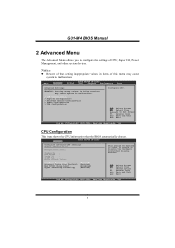
... BIOS SETUP UTILITY Configure advanced CPU settings Module Version:3F.07 Manufacturer:Intel Frequency : FSB Speed : Cache L1 : Cache L2 : Ratio Actual Value: This should be enabled in below sections may cause system to enable or disable the Hardware Prefetcher Disable Feature. Hardware Prefetcher [Enabled] Adjacent Cache Line Prefetch [Enabled] Max CPUID Value Limit [Disabled] Hyper Threading Technology [Enabled] Select Screen Select Item +- G31-M4 BIOS Manual 2 Advanced Menu The Advanced Menu allows you to Sub Screen...
... BIOS SETUP UTILITY Configure advanced CPU settings Module Version:3F.07 Manufacturer:Intel Frequency : FSB Speed : Cache L1 : Cache L2 : Ratio Actual Value: This should be enabled in below sections may cause system to enable or disable the Hardware Prefetcher Disable Feature. Hardware Prefetcher [Enabled] Adjacent Cache Line Prefetch [Enabled] Max CPUID Value Limit [Disabled] Hyper Threading Technology [Enabled] Select Screen Select Item +- G31-M4 BIOS Manual 2 Advanced Menu The Advanced Menu allows you to Sub Screen...
Bios Setup
Page 10
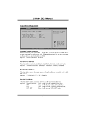
ECP Using Parallel port as ECP & EPP mode. 9 G31-M4 BIOS Manual SuperIO Configuration Advanced BIOS SETUP UTILITY Configure ITE8718 Super IO Chipset OnBoard Floppy Controller Serial Port1 Address Parallel Port Address Parallel Port Mode Parallel Port IRQ Restore on the system board and you installed another FDC or the system uses no floppy drive, select disabled in this field. Change Option F1 General Help F10 Save and Exit ESC Exit vxx.xx (C)Copyright 1985-200x, American Megatrends, Inc. Options: Enabled (Default) / Disabled Serial Port1...
ECP Using Parallel port as ECP & EPP mode. 9 G31-M4 BIOS Manual SuperIO Configuration Advanced BIOS SETUP UTILITY Configure ITE8718 Super IO Chipset OnBoard Floppy Controller Serial Port1 Address Parallel Port Address Parallel Port Mode Parallel Port IRQ Restore on the system board and you installed another FDC or the system uses no floppy drive, select disabled in this field. Change Option F1 General Help F10 Save and Exit ESC Exit vxx.xx (C)Copyright 1985-200x, American Megatrends, Inc. Options: Enabled (Default) / Disabled Serial Port1...
Bios Setup
Page 11
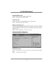
..., Inc. G31-M4 BIOS Manual ECP Mode DMA Channel This item allows you to select the IRQ for the onboard parallel port. Advanced BIOS SETUP UTILITY Hardware Health Configuration H/W Health Function Shutdown Temperature [Enabled] [Disabled] Enables Hardware Health Monitoring Device. H/W Health Function If with a monitoring system, the system will restore the system to the status before power failure or interrupt occurs. CPU Temperature System Temperature CPU FAN Speed SYS1 FAN Speed +12.0V +5.00V CPU Vcore Chipset Voltage DDR Voltage Select Screen Select Item...
..., Inc. G31-M4 BIOS Manual ECP Mode DMA Channel This item allows you to select the IRQ for the onboard parallel port. Advanced BIOS SETUP UTILITY Hardware Health Configuration H/W Health Function Shutdown Temperature [Enabled] [Disabled] Enables Hardware Health Monitoring Device. H/W Health Function If with a monitoring system, the system will restore the system to the status before power failure or interrupt occurs. CPU Temperature System Temperature CPU FAN Speed SYS1 FAN Speed +12.0V +5.00V CPU Vcore Chipset Voltage DDR Voltage Select Screen Select Item...
Bios Setup
Page 12
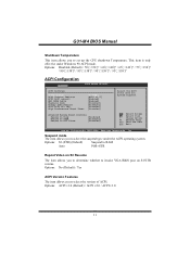
...8457; ACPI Configuration Advanced BIOS SETUP UTILITY ACPI Settings Suspend mode ACPI Version Features ACPI APIC support AMI OEMB table Headless mode Energy Lake Feature APIC ACPI SCI IRQ High Performance Event Timer [S3(STR)] [ACPI v1.0] [Enabled] [Enabled] [Disabled] [Diaabled] [Disabled] [Disabled] Advanced Resume Event Controls Resume On Ring [Disabled] Resume On PME# [Disabled] Resume On RTC Alarm [Disabled] Select the ACPI state used for System Suspend. Options: ACPI v1.0 (Default) / ACPI v2.0 / ACPI v3.0 11 Select Screen Select Item +- Options: No (Default) / Yes ACPI...
...8457; ACPI Configuration Advanced BIOS SETUP UTILITY ACPI Settings Suspend mode ACPI Version Features ACPI APIC support AMI OEMB table Headless mode Energy Lake Feature APIC ACPI SCI IRQ High Performance Event Timer [S3(STR)] [ACPI v1.0] [Enabled] [Enabled] [Disabled] [Diaabled] [Disabled] [Disabled] Advanced Resume Event Controls Resume On Ring [Disabled] Resume On PME# [Disabled] Resume On RTC Alarm [Disabled] Select the ACPI state used for System Suspend. Options: ACPI v1.0 (Default) / ACPI v2.0 / ACPI v3.0 11 Select Screen Select Item +- Options: No (Default) / Yes ACPI...
Bios Setup
Page 15
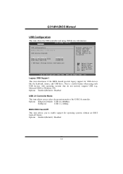
G31-M4 BIOS Manual USB Configuration This item shows the USB controller and using such USB devices with operating systems that do not natively support USB (e.g. Ad vanced BIOS SETUP UTILITY USB Configuration Module Version - 2.24.3-13.4 USB Devices Enabled: Legacy USB Support USB 2.0 Controller Mode BIOS EHCI Hand-Off [ Enable d] [ HiSpee d] [ Enable d] > USB Mass Storage Device Configuration Enables support for USB devices like the keyboard, mouse, and USB drive. Legacy USB Support This item determines if the BIOS should provide legacy support for legacy USB. Select Screen ...
G31-M4 BIOS Manual USB Configuration This item shows the USB controller and using such USB devices with operating systems that do not natively support USB (e.g. Ad vanced BIOS SETUP UTILITY USB Configuration Module Version - 2.24.3-13.4 USB Devices Enabled: Legacy USB Support USB 2.0 Controller Mode BIOS EHCI Hand-Off [ Enable d] [ HiSpee d] [ Enable d] > USB Mass Storage Device Configuration Enables support for USB devices like the keyboard, mouse, and USB drive. Legacy USB Support This item determines if the BIOS should provide legacy support for legacy USB. Select Screen ...
Bios Setup
Page 18
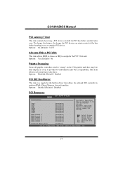
... built-in driver that allows the onboard IDE controller to be used by Legacy ISA devices. G31-M4 BIOS Manual PCI Latency Timer This item controls how long a PCI device can retain control of the bus before another PCI device. This item allows such snooping to provide boot information and VGA compatibility. Reserved: Specified IRQ is available to perform DMA (Direct Memory Access) transfers. The longer the latency, the longer the PCI device can hold the PCI bus before...
... built-in driver that allows the onboard IDE controller to be used by Legacy ISA devices. G31-M4 BIOS Manual PCI Latency Timer This item controls how long a PCI device can retain control of the bus before another PCI device. This item allows such snooping to provide boot information and VGA compatibility. Reserved: Specified IRQ is available to perform DMA (Direct Memory Access) transfers. The longer the latency, the longer the PCI device can hold the PCI bus before...
Bios Setup
Page 25
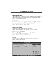
.... Options: Auto (Default) / Disabled Video Function Configuration BIOS SETUP UTILITY Chipset Video Function Configuration DVMT Mode Select DVMT/FIXED Memory [DVMT Mode] [256MB] Options Fixed Mode DVMT Mode Select Screen Select Item +- Change Option F1 General Help F10 Save and Exit ESC Exit vxx.xx (C)Copyright 1985-200x, American Megatrends, Inc. 24 When this area is decided, this area of peripherals that enables or disables the PCI Express port. Options: PEG/PCI (Default) / IGD / PCI/IGD / PCI/PEG / PEG/IGD Internal Graphics Mode Select...
.... Options: Auto (Default) / Disabled Video Function Configuration BIOS SETUP UTILITY Chipset Video Function Configuration DVMT Mode Select DVMT/FIXED Memory [DVMT Mode] [256MB] Options Fixed Mode DVMT Mode Select Screen Select Item +- Change Option F1 General Help F10 Save and Exit ESC Exit vxx.xx (C)Copyright 1985-200x, American Megatrends, Inc. 24 When this area is decided, this area of peripherals that enables or disables the PCI Express port. Options: PEG/PCI (Default) / IGD / PCI/IGD / PCI/PEG / PEG/IGD Internal Graphics Mode Select...
Bios Setup
Page 26
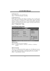
... DVMT mode. If the BIOS has high speed USB support, the support will set the optimum amount of the unified memory architecture (UMA) concept. Options: Enabled (Default) / Disabled 25 This BIOS itself may/may not have high speed USB support. Options: 256MB (Default) / 128MB South Bridge Configuration BIOS SETUP UTILITY Chipset South Bridge Chipset Configuration USB Functions USB 2.0 Controller Audio Controller [8 USB Ports] [Enabled] [Azalia] Onboard Lan Control Onboard Lan Boot ROM MAC ID Information [Enabled] [Disabled] SMBUS Controller [Enabled] SLP_S4# Min. USB Functions...
... DVMT mode. If the BIOS has high speed USB support, the support will set the optimum amount of the unified memory architecture (UMA) concept. Options: Enabled (Default) / Disabled 25 This BIOS itself may/may not have high speed USB support. Options: 256MB (Default) / 128MB South Bridge Configuration BIOS SETUP UTILITY Chipset South Bridge Chipset Configuration USB Functions USB 2.0 Controller Audio Controller [8 USB Ports] [Enabled] [Azalia] Onboard Lan Control Onboard Lan Boot ROM MAC ID Information [Enabled] [Disabled] SMBUS Controller [Enabled] SLP_S4# Min. USB Functions...

Bios Setup
Page 27
.../ Disabled Onboard Lan Boot Rom This item allows you to select the Audio support. G31-M4 BIOS Manual Audio Controller This item allows you to select the status of Onboard LAN Boot ROM. Options: Disabled (Default) / Enabled MAC ID Information This item shows the LAN MAC ID. Options: Enabled (Default) / Disabled SLP_S4# Min. Assertion Width Options: 1 to 2 seconds (Default) / 4 to 5 seconds / 3 to 4 seconds / 2 to enable or disable the Onboard LAN. SMBUS Controller This BIOS feature controls the I/O buffers for the SMBus. Options: Azalia (Default) / All Disabled Onboard Lan Control This...
.../ Disabled Onboard Lan Boot Rom This item allows you to select the Audio support. G31-M4 BIOS Manual Audio Controller This item allows you to select the status of Onboard LAN Boot ROM. Options: Disabled (Default) / Enabled MAC ID Information This item shows the LAN MAC ID. Options: Enabled (Default) / Disabled SLP_S4# Min. Assertion Width Options: 1 to 2 seconds (Default) / 4 to 5 seconds / 3 to 4 seconds / 2 to enable or disable the Onboard LAN. SMBUS Controller This BIOS feature controls the I/O buffers for the SMBus. Options: Azalia (Default) / All Disabled Onboard Lan Control This...
Bios Setup
Page 31
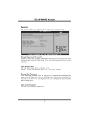
G31-M4 BIOS Manual Security This sub-menu allows you to change them. BIOS SETUP UTILITY Exit Security Settings Supervisor Password :Not Installed User Password :Not Installed Change Supervisor Password User Access Level Change User Password Clear User Password Password Check [Full Access] [Setup] Boot Sector Virus Protection [Disabled] Install or Change the password. Options: Full Access (Default) / No Access / View Only / Limited Change User Password If the Supervisor Password is for clearing user password. 30 Clear User Password This item is not set, then the User ...
G31-M4 BIOS Manual Security This sub-menu allows you to change them. BIOS SETUP UTILITY Exit Security Settings Supervisor Password :Not Installed User Password :Not Installed Change Supervisor Password User Access Level Change User Password Clear User Password Password Check [Full Access] [Setup] Boot Sector Virus Protection [Disabled] Install or Change the password. Options: Full Access (Default) / No Access / View Only / Limited Change User Password If the Supervisor Password is for clearing user password. 30 Clear User Password This item is not set, then the User ...


