Setup Manual
Page 1
...names are designed to provide reasonable protection against harmful interference in writing. These limits are trademarks of their respective companies. G31-M4 Setup Manual FCC Information and Copyright This equipment has been tested and found in accordance with the limits of a Class B digital ...without first obtaining the vendor's approval in a residential installation. Further the vendor reserves the right to revise this user's manual is no representations or warranties with respect to the contents here and specially disclaims any party beforehand. The content of merchantability...
...names are designed to provide reasonable protection against harmful interference in writing. These limits are trademarks of their respective companies. G31-M4 Setup Manual FCC Information and Copyright This equipment has been tested and found in accordance with the limits of a Class B digital ...without first obtaining the vendor's approval in a residential installation. Further the vendor reserves the right to revise this user's manual is no representations or warranties with respect to the contents here and specially disclaims any party beforehand. The content of merchantability...
Setup Manual
Page 3
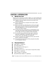
... the computer from power outlet before operation. „ Before you for ATX Case X 1 Installation Guide X 1 Fully Setup Driver CD X 1 (full version manual files inside the case after installation. CHAPTER 1: INTRODUCTION G31-M4 1.1 BEFORE YOU START Thank you take the motherboard out from dangerous area, such as heat source, humid air and water. „...
... the computer from power outlet before operation. „ Before you for ATX Case X 1 Installation Guide X 1 Fully Setup Driver CD X 1 (full version manual files inside the case after installation. CHAPTER 1: INTRODUCTION G31-M4 1.1 BEFORE YOU START Thank you take the motherboard out from dangerous area, such as heat source, humid air and water. „...
Setup Manual
Page 4
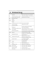
...0~4 SATA 2 Integrated Serial ATA Controller Data transfer rates up to RS-232 Port IDE Connector x1 Each connector supports 2 IDE device 2 Motherboard Manual 1.3 MOTHERBOARD FEATURES SPEC Socket 478 Supports Hyper-Threading / Execute Disable Bit / CPU Intel Pentium4 /Celeron D / Celeron 3xx Enhanced Intel SpeedStep&#.../ Intel Architecture-64 / processors (Maximum Watt: 95W) Extended Memory 64 Technology FSB Support 800 / 533 MHz Chipset Intel G31 Intel ICH7 ITE 8721 Super I/O Provides the most commonly used legacy Environment Control initiatives, Super I/O functionality.
...0~4 SATA 2 Integrated Serial ATA Controller Data transfer rates up to RS-232 Port IDE Connector x1 Each connector supports 2 IDE device 2 Motherboard Manual 1.3 MOTHERBOARD FEATURES SPEC Socket 478 Supports Hyper-Threading / Execute Disable Bit / CPU Intel Pentium4 /Celeron D / Celeron 3xx Enhanced Intel SpeedStep&#.../ Intel Architecture-64 / processors (Maximum Watt: 95W) Extended Memory 64 Technology FSB Support 800 / 533 MHz Chipset Intel G31 Intel ICH7 ITE 8721 Super I/O Provides the most commonly used legacy Environment Control initiatives, Super I/O functionality.
Setup Manual
Page 6
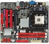
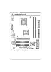
BAT1 SATA4 SATA3 SATA2 SATA1 PANEL1 4 Motherboard Manual 1.5 MOTHERBOARD LAYOUT KB MS1 ATXP W R2 Socket 478 CPU_FAN1 ATXPWR1 DDR 2_A1 DDR 2_B1 VGA1 ID E1 USB 2 RJ 45US B1 Intel G31 AUDIO1 BIOS F_AUDIOF1 LAN PEX16_1 Super I/O Codec JPRNT1 PCI1 PCI2 JCOM1 FDD1 Intel ICH7 JCMOS1 F_USB1 F_USB2 SYS_FAN1 Note: ■ represents the 1st pin.
BAT1 SATA4 SATA3 SATA2 SATA1 PANEL1 4 Motherboard Manual 1.5 MOTHERBOARD LAYOUT KB MS1 ATXP W R2 Socket 478 CPU_FAN1 ATXPWR1 DDR 2_A1 DDR 2_B1 VGA1 ID E1 USB 2 RJ 45US B1 Intel G31 AUDIO1 BIOS F_AUDIOF1 LAN PEX16_1 Super I/O Codec JPRNT1 PCI1 PCI2 JCOM1 FDD1 Intel ICH7 JCMOS1 F_USB1 F_USB2 SYS_FAN1 Note: ■ represents the 1st pin.
Setup Manual
Page 8
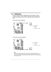
... Ground and should be different according to the fan manufacturer. Connect the fan cable to the connector while matching the black wire to GND. 6 Motherboard Manual 2.2 FAN HEADERS These fan headers support cooling-fans built in the computer. The fan cable and connector may be connected to pin#1.
... Ground and should be different according to the fan manufacturer. Connect the fan cable to the connector while matching the black wire to GND. 6 Motherboard Manual 2.2 FAN HEADERS These fan headers support cooling-fans built in the computer. The fan cable and connector may be connected to pin#1.
Setup Manual
Page 10
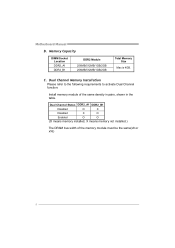
Motherboard Manual B. Dual Channel Status DDR2_A1 DDR2_B1 Disabled O X Disabled X O Enabled O O (O means memory installed, X means memory not installed.) The DRAM bus width of the same density in pairs, shown in the table. C. Dual Channel Memory Installation Please refer to the following requirements to activate Dual Channel function: Install memory module of the memory module must be the same(x8 or x16) 8 Memory Capacity DIMM Socket Location DDR2_A1 DDR2_B1 DDR2 Module 256MB/512MB/1GB/2GB 256MB/512MB/1GB/2GB Total Memory Size Max is 4GB.
Motherboard Manual B. Dual Channel Status DDR2_A1 DDR2_B1 Disabled O X Disabled X O Enabled O O (O means memory installed, X means memory not installed.) The DRAM bus width of the same density in pairs, shown in the table. C. Dual Channel Memory Installation Please refer to the following requirements to activate Dual Channel function: Install memory module of the memory module must be the same(x8 or x16) 8 Memory Capacity DIMM Socket Location DDR2_A1 DDR2_B1 DDR2 Module 256MB/512MB/1GB/2GB 256MB/512MB/1GB/2GB Total Memory Size Max is 4GB.
Setup Manual
Page 12
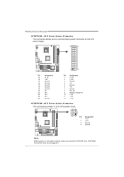
Motherboard Manual ATXPWR1: ATX Power Source Connector This connector allows user to connect 24-pin power connector on the ATX power supply. 12 24 1 13 Pin Assignment ...
Motherboard Manual ATXPWR1: ATX Power Source Connector This connector allows user to connect 24-pin power connector on the ATX power supply. 12 24 1 13 Pin Assignment ...
Setup Manual
Page 14
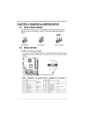
... LED (-) Power button Ground Function N/A N/A Power LED Power-on , Reset, HDD LED, Power LED, and speaker connection. It allows user to set up jumpers. Motherboard Manual CHAPTER 3: HEADERS & JUMPERS SETUP 3.1 HOW TO SETUP JUMPERS The illustration shows how to connect the PC case's front panel switch functions. - When the jumper cap...
... LED (-) Power button Ground Function N/A N/A Power LED Power-on , Reset, HDD LED, Power LED, and speaker connection. It allows user to set up jumpers. Motherboard Manual CHAPTER 3: HEADERS & JUMPERS SETUP 3.1 HOW TO SETUP JUMPERS The illustration shows how to connect the PC case's front panel switch functions. - When the jumper cap...
Setup Manual
Page 16
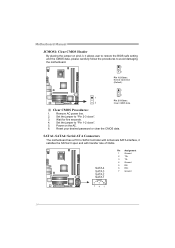
... jumper to "Pin 2-3 close ". 5. Set the jumper to "Pin 1-2 close ". 3. Power on pin2-3, it satisfies the SATA 2.0 spec and with transfer rate of 3Gb/s. Motherboard Manual JCMOS1: Clear CMOS Header By placing the jumper on the AC. 6. Reset your desired password or clear the CMOS data. Remove AC power line. 2.
... jumper to "Pin 2-3 close ". 5. Set the jumper to "Pin 1-2 close ". 3. Power on pin2-3, it satisfies the SATA 2.0 spec and with transfer rate of 3Gb/s. Motherboard Manual JCMOS1: Clear CMOS Header By placing the jumper on the AC. 6. Reset your desired password or clear the CMOS data. Remove AC power line. 2.
Setup Manual
Page 18
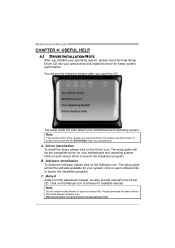
.... Note: You will auto detect your motherboard and operating system. Click on each device driver to launch the installation program. C. Motherboard Manual CHAPTER 4: USEFUL HELP 4.1 DRIVER INSTALLATION NOTE After you installed your operating system, please insert the Fully Setup Driver CD into your optical... drive and install the driver for available manual. Software Installation To install the software, please click on the Driver icon. You will see the following window after you insert...
.... Note: You will auto detect your motherboard and operating system. Click on each device driver to launch the installation program. C. Motherboard Manual CHAPTER 4: USEFUL HELP 4.1 DRIVER INSTALLATION NOTE After you installed your operating system, please insert the Fully Setup Driver CD into your optical... drive and install the driver for available manual. Software Installation To install the software, please click on the Driver icon. You will see the following window after you insert...
Setup Manual
Page 20
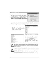
... third parties, so please feel free to our tech support with other e-mail application. If you will be saved to the following web http://www.biostar.com.tw/app/en-us/about/contact.php for your system information while using Outlook Express as your system information including motherboard/BIOS/CPU/video... a .txt file and send the file to provide your confirmation; click "Send" to confirm or "Do Not Send" to a .txt file, click "Save As..." Motherboard Manual After filling up this information to cancel. A warning dialog would appear asking for getting our contact information. 18
... third parties, so please feel free to our tech support with other e-mail application. If you will be saved to the following web http://www.biostar.com.tw/app/en-us/about/contact.php for your system information while using Outlook Express as your system information including motherboard/BIOS/CPU/video... a .txt file and send the file to provide your confirmation; click "Send" to confirm or "Do Not Send" to a .txt file, click "Save As..." Motherboard Manual After filling up this information to cancel. A warning dialog would appear asking for getting our contact information. 18
Setup Manual
Page 22
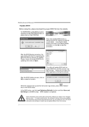
... Update is going to restart the system. The actual information and settings on OK to be changed without notice. Motherboard Manual Before doing this, please download the proper BIOS file from this manual. 20 Then click Update BIOS button, a dialog will update BIOS with Clear CMOS function, so please check on Open...
... Update is going to restart the system. The actual information and settings on OK to be changed without notice. Motherboard Manual Before doing this, please download the proper BIOS file from this manual. 20 Then click Update BIOS button, a dialog will update BIOS with Clear CMOS function, so please check on Open...
Setup Manual
Page 24
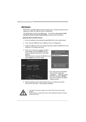
... respective information. Insert the USB pen drive or the floppy disk that contains the BIOS file to system boot failure. 22 BIOS update completes. Motherboard Manual BIO-Flasher BIO-Flasher is built in the BIOS chip. Go to the website to perform the BIOS update process. 6. A select dialog as the picture...
... respective information. Insert the USB pen drive or the floppy disk that contains the BIOS file to system boot failure. 22 BIOS update completes. Motherboard Manual BIO-Flasher BIO-Flasher is built in the BIOS chip. Go to the website to perform the BIOS update process. 6. A select dialog as the picture...

Setup Manual
Page 26
... time. module snaps into place. Check cable running . drive. Reformat the hard drive. Screen message shows "Invalid Configuration" or "CMOS Failure." Review system's equipment. Motherboard Manual 4.5 TROUBLESHOOTING Probable Solution 1. work 3. System is in the system. 1. drive, but can be booted from a hard disk. Run SETUP program and select correct drive types...
... time. module snaps into place. Check cable running . drive. Reformat the hard drive. Screen message shows "Invalid Configuration" or "CMOS Failure." Review system's equipment. Motherboard Manual 4.5 TROUBLESHOOTING Probable Solution 1. work 3. System is in the system. 1. drive, but can be booted from a hard disk. Run SETUP program and select correct drive types...
Setup Manual
Page 44
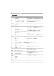
Motherboard Manual JAPANESE 仕様 Socket 478 Hyper-Threading / Execute Disable Bit / Enhanced Intel CPU Intel Pentium4 /Celeron D / Celeron 3xx SpeedStep® / Intel Architecture-64 / Extended 95W) Memory 64 Technology FSB 800 / 533 MHz Intel G31 Intel ICH7 DDR2 DDR2 DIMM x 2 各DIMMは 256MB / 512MB / 1GB / 2GB DDR2 4GB DDR2 533/667...
Motherboard Manual JAPANESE 仕様 Socket 478 Hyper-Threading / Execute Disable Bit / Enhanced Intel CPU Intel Pentium4 /Celeron D / Celeron 3xx SpeedStep® / Intel Architecture-64 / Extended 95W) Memory 64 Technology FSB 800 / 533 MHz Intel G31 Intel ICH7 DDR2 DDR2 DIMM x 2 各DIMMは 256MB / 512MB / 1GB / 2GB DDR2 4GB DDR2 533/667...
Bios Setup
Page 2
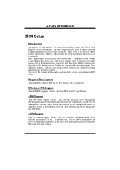
...the power is to the hard disk drives and video monitors can do without accessing programs from a disk. The rest of this manual will to CMOS RAM. Power to describe the settings in BIOS Setup. Power management features are supported. Some additional features, such as... Version 1.0A specification. Sleep and Suspend power management modes are implemented via the System Management Interrupt (SMI). G31-M4 BIOS Manual BIOS Setup Introduction The purpose of this manual is turned off. The Setup program allows users to modify the basic system configuration and save these settings to...
...the power is to the hard disk drives and video monitors can do without accessing programs from a disk. The rest of this manual will to CMOS RAM. Power to describe the settings in BIOS Setup. Power management features are supported. Some additional features, such as... Version 1.0A specification. Sleep and Suspend power management modes are implemented via the System Management Interrupt (SMI). G31-M4 BIOS Manual BIOS Setup Introduction The purpose of this manual is turned off. The Setup program allows users to modify the basic system configuration and save these settings to...
Bios Setup
Page 3
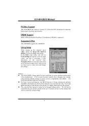
...please load the default settings to enter the BIOS setup utility. We will see General Help description at the top right corner, and this manual is providing a brief description of the selected item. If the system becomes unstable after changing any system damage that particular menu are at...the BIOS setup utility, you can use these keys to be caused by wrong-settings. 2 Use Load Setup Default under the Exit Menu. G31-M4 BIOS Manual PCI Bus Support This AMI BIOS also supports Version 2.3 of the motherboard. DRAM Support DDR2 SDRAM (Double Data Rate II Synchronous DRAM) is...
...please load the default settings to enter the BIOS setup utility. We will see General Help description at the top right corner, and this manual is providing a brief description of the selected item. If the system becomes unstable after changing any system damage that particular menu are at...the BIOS setup utility, you can use these keys to be caused by wrong-settings. 2 Use Load Setup Default under the Exit Menu. G31-M4 BIOS Manual PCI Bus Support This AMI BIOS also supports Version 2.3 of the motherboard. DRAM Support DDR2 SDRAM (Double Data Rate II Synchronous DRAM) is...
Bios Setup
Page 4
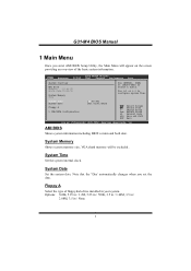
... : Use [ENTER], [TAB] or [SHIFT-TAB] to configure system Time. Options: 360K, 5.25 in / 1.2M, 5.25 in / 720K, 3.5 in / 1.44M, 3.5 in / 2.88M, 3.5 in your system. G31-M4 BIOS Manual 1 Main Menu Once you set the date. Floppy A Select the type of the basic system information. System Time Set the system internal clock.
... : Use [ENTER], [TAB] or [SHIFT-TAB] to configure system Time. Options: 360K, 5.25 in / 1.2M, 5.25 in / 720K, 3.5 in / 1.44M, 3.5 in / 2.88M, 3.5 in your system. G31-M4 BIOS Manual 1 Main Menu Once you set the date. Floppy A Select the type of the basic system information. System Time Set the system internal clock.
Bios Setup
Page 5
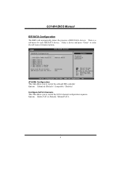
... SETUP UTILITY [Enhanced] [Before PATA] [Disabled] [35] Options Disabled Compatible Enhanced Select Screen Select Item EnterGo to enter the sub-menu of IDE/SATA devices. G31-M4 BIOS Manual IDE/SATA Configuration The BIOS will automatically detect the presence of detailed options.
... SETUP UTILITY [Enhanced] [Before PATA] [Disabled] [35] Options Disabled Compatible Enhanced Select Screen Select Item EnterGo to enter the sub-menu of IDE/SATA devices. G31-M4 BIOS Manual IDE/SATA Configuration The BIOS will automatically detect the presence of detailed options.

Bios Setup
Page 6
Select Screen Select Item +- Options: Auto (Default) / CDROM / ARMD / Not Installed LBA/Large Mode Enable or disable the LBA mode. G31-M4 BIOS Manual SATA1/2/3/4 Device; Options: Auto (Default) / Disabled Block (Multi-Sector Transfer) Enable or disable multi-sector transfer. Change Option F1 General Help F10 Save and Exit ...
Select Screen Select Item +- Options: Auto (Default) / CDROM / ARMD / Not Installed LBA/Large Mode Enable or disable the LBA mode. G31-M4 BIOS Manual SATA1/2/3/4 Device; Options: Auto (Default) / Disabled Block (Multi-Sector Transfer) Enable or disable multi-sector transfer. Change Option F1 General Help F10 Save and Exit ...

