Operation Manual
Page 1
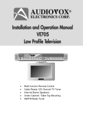
• Multi-function Remote Control • Cable Ready 125 Channel TV Tuner • Internal Stereo Speakers • Under Cabinet / Table Top Mounting • AM/FM Radio Tuner 0
• Multi-function Remote Control • Cable Ready 125 Channel TV Tuner • Internal Stereo Speakers • Under Cabinet / Table Top Mounting • AM/FM Radio Tuner 0
Operation Manual
Page 2
...important operating and maintenance (servicing) instructions in the literature accompanying the appliance. This symbol is intended to alert the user to the presence of electric shock to persons. CAUT ION CAUTION: TO REDUCE THE RISK OF ELECTRIC SHOCK, DO NOT REMOVE COVER (OR BACK). NO USER-SERVICEABLE PARTS ...INSIDE. TO PREVENT ELECTRIC SHOCK: DO NOT USE THIS POLARIZED AC PLUG WITH AN EXTENSION CORD, RECEPTACLE OR OTHER OUTLET UNLESS THE BLADES CAN BE FULLY INSERTED TO ...
...important operating and maintenance (servicing) instructions in the literature accompanying the appliance. This symbol is intended to alert the user to the presence of electric shock to persons. CAUT ION CAUTION: TO REDUCE THE RISK OF ELECTRIC SHOCK, DO NOT REMOVE COVER (OR BACK). NO USER-SERVICEABLE PARTS ...INSIDE. TO PREVENT ELECTRIC SHOCK: DO NOT USE THIS POLARIZED AC PLUG WITH AN EXTENSION CORD, RECEPTACLE OR OTHER OUTLET UNLESS THE BLADES CAN BE FULLY INSERTED TO ...
Operation Manual
Page 3
.../TV technician for help NOTE: Record Model Number and Serial Number in the space provided below. Reorient or relocate the receiving antenna - Connect the equipment into an outlet on , the user is , in strict accordance with the manufacture's instructions, may cause or receive unwanted interference. SERIAL No. 2- INFORMATION This equipment generates and uses radio frequency energy and if not installed and used properly, that is...
.../TV technician for help NOTE: Record Model Number and Serial Number in the space provided below. Reorient or relocate the receiving antenna - Connect the equipment into an outlet on , the user is , in strict accordance with the manufacture's instructions, may cause or receive unwanted interference. SERIAL No. 2- INFORMATION This equipment generates and uses radio frequency energy and if not installed and used properly, that is...
Operation Manual
Page 4
... the manufacture's instructions, and should not be operated only from the type of power supply in a wet basement, near water - These openings must not be retained for cleaning. If you are not sure of the type of power source indicated on an unstable cart, stand, tripod bracket, or table. If you are unable to replace your electrician to insert the plug fully into...
... the manufacture's instructions, and should not be operated only from the type of power supply in a wet basement, near water - These openings must not be retained for cleaning. If you are not sure of the type of power source indicated on an unstable cart, stand, tripod bracket, or table. If you are unable to replace your electrician to insert the plug fully into...
Operation Manual
Page 5
... a need or service. 4- A. B. Adjust only those controls that are not likely to be walked on outside antenna system should not be fatal. 17. F. Power Lines - When the power-supply cord or plug is left unattended and unused for long periods of antenna- If the product has been exposed to qualified service personnel. 20. E. this product from the wall outlet and disconnect the antenna or cable...
... a need or service. 4- A. B. Adjust only those controls that are not likely to be walked on outside antenna system should not be fatal. 17. F. Power Lines - When the power-supply cord or plug is left unattended and unused for long periods of antenna- If the product has been exposed to qualified service personnel. 20. E. this product from the wall outlet and disconnect the antenna or cable...
Operation Manual
Page 6
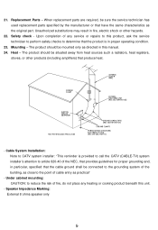
... cable entry as close to reduce the risk of any heating or cooking product beneath this manual. 24. When replacement parts are required, be sure the service technician has used replacement parts specified by the manufacturer or that the cable ground shall be situated away from heat sources such a radiators, heat registers, stoves, or other hazards. 22. Heat - Speaker Impedance Marking: External 8 ohms speaker...
... cable entry as close to reduce the risk of any heating or cooking product beneath this manual. 24. When replacement parts are required, be sure the service technician has used replacement parts specified by the manufacturer or that the cable ground shall be situated away from heat sources such a radiators, heat registers, stoves, or other hazards. 22. Heat - Speaker Impedance Marking: External 8 ohms speaker...

Operation Manual
Page 7
... Installation Remote Control Functions Modes of Operation Technical Specifications Troubleshooting Check List Introduction 1 Important Safety Information 3 Table of Contents 6 Contents of package 7 Under Cabinet Installation 8 Countertop/Desktop Installation 9 Front Panel Controls 10 Rear Panel Controls 11 Battery Installation 12 Remote Control Functions 13 Operation 14 Initial Set up 14 Channel Tuning Set up 14 Positioning the Screen 14 Setting the Time 14 Setting and Activating The Alarm 15 Deactivating Alarm 15 Setting the Alarm Tones 15 Setting the Cable TV Mode...
... Installation Remote Control Functions Modes of Operation Technical Specifications Troubleshooting Check List Introduction 1 Important Safety Information 3 Table of Contents 6 Contents of package 7 Under Cabinet Installation 8 Countertop/Desktop Installation 9 Front Panel Controls 10 Rear Panel Controls 11 Battery Installation 12 Remote Control Functions 13 Operation 14 Initial Set up 14 Channel Tuning Set up 14 Positioning the Screen 14 Setting the Time 14 Setting and Activating The Alarm 15 Deactivating Alarm 15 Setting the Alarm Tones 15 Setting the Cable TV Mode...
Operation Manual
Page 8
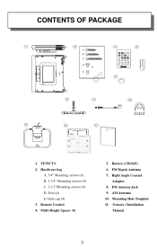
CONTENTS OF PACKAGE PWR T EL TV VOL M U TE CH ENT CH VOL SEEK A /V F M /A M 1 2 3 ER ASE 4 5 6 AD D 7 8 9 0 1. Foot (4) E. Battery (CR2025) 6. AM Antenna 10. Remote Control 4. Hardware bag A. 3/4" Mounting screws (4) B. 1-1/4" Mounting screws (4) C. 1-1/2"Mounting screws (4) D. Multi Height Spacer (4) 5. Owners / Installation Manual 7 - VE705 TV 2. Right Angle Coaxial Adaptor 8. FM Antenna Jack 9. FM Dipole Antenna 7. Mounting Hole Template 11. Hole cap (4) 3.
CONTENTS OF PACKAGE PWR T EL TV VOL M U TE CH ENT CH VOL SEEK A /V F M /A M 1 2 3 ER ASE 4 5 6 AD D 7 8 9 0 1. Foot (4) E. Battery (CR2025) 6. AM Antenna 10. Remote Control 4. Hardware bag A. 3/4" Mounting screws (4) B. 1-1/4" Mounting screws (4) C. 1-1/2"Mounting screws (4) D. Multi Height Spacer (4) 5. Owners / Installation Manual 7 - VE705 TV 2. Right Angle Coaxial Adaptor 8. FM Antenna Jack 9. FM Dipole Antenna 7. Mounting Hole Template 11. Hole cap (4) 3.
Operation Manual
Page 9
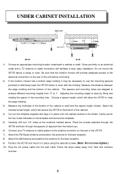
...-up) 6) Connect your TV antenna or cable system to the bottom of the cabinet. 4) Cut out the template supplied and tape it may be drilled. Do not mount the VE705 above . Adjusting the mounting height is done by lifting and rotating the spacer in place using the selected screws. (Note: Do not over-tighten.) 10) Plug the AC power cable into the wall outlet...
...-up) 6) Connect your TV antenna or cable system to the bottom of the cabinet. 4) Cut out the template supplied and tape it may be drilled. Do not mount the VE705 above . Adjusting the mounting height is done by lifting and rotating the spacer in place using the selected screws. (Note: Do not over-tighten.) 10) Plug the AC power cable into the wall outlet...
Operation Manual
Page 10
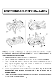
...: Do not over and remove the blank cover (#4) 5) Connect the plug of the unit and then turn it is perpendicular to the front of the LCD monitor into the connector (#3). (Note: align the "L" and "R" stamped on the screen mounting bracket with the "L" and "R" molded into the removal slots. COUNTERTOP/DESKTOP INSTALLATION NOTE: Use caution to avoid damaging the LCD screen and the main unit...
...: Do not over and remove the blank cover (#4) 5) Connect the plug of the unit and then turn it is perpendicular to the front of the LCD monitor into the connector (#3). (Note: align the "L" and "R" stamped on the screen mounting bracket with the "L" and "R" molded into the removal slots. COUNTERTOP/DESKTOP INSTALLATION NOTE: Use caution to avoid damaging the LCD screen and the main unit...

Operation Manual
Page 11
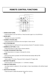
...) CHANNEL BUTTONS (TS-Left Side) - Displays the channel/station number, time, and selected source. 19) REMOTE INFRARED SENSORS-These sensors receive infrared command signals from the 10- Press and Hold this button to add a selected channel. 4) DEL BUTTON - BUTTON - Press this button to select AM Radio mode. 9) MUTE BUTTON - Press this button to lower the volume. 16) SEEK BUTTONS (TS-Right Side) - Press this button to set the TIME, ALARM, TV Mode or Speaker Mode. 3) ADD BUTTON - Selected Preset Channel...
...) CHANNEL BUTTONS (TS-Left Side) - Displays the channel/station number, time, and selected source. 19) REMOTE INFRARED SENSORS-These sensors receive infrared command signals from the 10- Press and Hold this button to add a selected channel. 4) DEL BUTTON - BUTTON - Press this button to select AM Radio mode. 9) MUTE BUTTON - Press this button to lower the volume. 16) SEEK BUTTONS (TS-Right Side) - Press this button to set the TIME, ALARM, TV Mode or Speaker Mode. 3) ADD BUTTON - Selected Preset Channel...

Operation Manual
Page 12
REAR PANEL CONNECTIONS 1 2 3 4 1) AC LINE CORD - Allows the VE705 to be connected to an external antenna for the reception of AM broadcast signals. 4) TV ANTENNA (75 OHM ANTENNA CONNECTOR) -Allows the VE705 to be connected to a 75-Ohm external coaxial antenna for the reception of FM broadcast signals. 3) AM ANTENNA - hand held remote control unit. Connects to a 75-ohm external coaxial antenna or cable TV system. 11- Allows the VE705 to be connected to AC power outlet 2) FM ANTENNA -
REAR PANEL CONNECTIONS 1 2 3 4 1) AC LINE CORD - Allows the VE705 to be connected to an external antenna for the reception of AM broadcast signals. 4) TV ANTENNA (75 OHM ANTENNA CONNECTOR) -Allows the VE705 to be connected to a 75-Ohm external coaxial antenna for the reception of FM broadcast signals. 3) AM ANTENNA - hand held remote control unit. Connects to a 75-ohm external coaxial antenna or cable TV system. 11- Allows the VE705 to be connected to AC power outlet 2) FM ANTENNA -
Operation Manual
Page 13
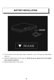
BATTERY INSTALLATION 1) Turn the Remote Control face down. Place a fingernail, or coin in the open slot, slide battery holder out. 2) Install the CR2025 battery into its proper slot. (Note: Be sure to observe the correct polarity when inserting the battery). 3) Slide the battery holder in until it clicks. 12-
BATTERY INSTALLATION 1) Turn the Remote Control face down. Place a fingernail, or coin in the open slot, slide battery holder out. 2) Install the CR2025 battery into its proper slot. (Note: Be sure to observe the correct polarity when inserting the battery). 3) Slide the battery holder in until it clicks. 12-
Operation Manual
Page 14
...) Use these buttons to advance to scan and store all active TV channels in memory. 5. VOLUME UP/DOWN BUTTONS (TS) Press these buttons to mute the audio (+++++ will alternate between AM and FM. 8. DELETE BUTTON (DEL) Press this button to turn the VE705 on the VE705 3. MUTE BUTTON (MUTE) Press this button is pressed, the VE705 will blink on display). 10. Press the button again to turn the VE705 off. 2. NUMERICAL BUTTONS...
...) Use these buttons to advance to scan and store all active TV channels in memory. 5. VOLUME UP/DOWN BUTTONS (TS) Press these buttons to mute the audio (+++++ will alternate between AM and FM. 8. DELETE BUTTON (DEL) Press this button to turn the VE705 on the VE705 3. MUTE BUTTON (MUTE) Press this button is pressed, the VE705 will blink on display). 10. Press the button again to turn the VE705 off. 2. NUMERICAL BUTTONS...

Operation Manual
Page 15
... VE705 is concluded. Pressing the PWR button on , it will not respond to the time display. 14- OPERATION Initial Setup: This unit defaults to operate the unit. Please wait while the unit auto-programs before attempting to cable TV mode. CHANNEL TUNING SET UP In addition to normal broadcast reception of VHF and UHF channels, if you are performed with the VE705 turned off and pivot the screen...
... VE705 is concluded. Pressing the PWR button on , it will not respond to the time display. 14- OPERATION Initial Setup: This unit defaults to operate the unit. Please wait while the unit auto-programs before attempting to cable TV mode. CHANNEL TUNING SET UP In addition to normal broadcast reception of VHF and UHF channels, if you are performed with the VE705 turned off and pivot the screen...
Operation Manual
Page 16
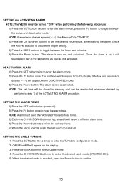
... a different alarm tone. 4) Press the Power button to confirm the selected tone. 5) When the alarm sounds, press the set time will appear on the display. 3) Press the SEEK button to select Cable mode. 4) Press the CH UP/DOWN button(s) to select the desired cable mode (STD/IRC/HRC). 5) When the desired mode is set and activated. NOTE: The set button to turn it is now deactivated. NOTE...
... a different alarm tone. 4) Press the Power button to confirm the selected tone. 5) When the alarm sounds, press the set time will appear on the display. 3) Press the SEEK button to select Cable mode. 4) Press the CH UP/DOWN button(s) to select the desired cable mode (STD/IRC/HRC). 5) When the desired mode is set and activated. NOTE: The set button to turn it is now deactivated. NOTE...

Operation Manual
Page 17
SETTING THE AIR TV MODE 1) Press the SET button three times to enter the TV/Cable configuration mode. 2) Press the SEEK button to select the AIR mode. 3) Press the POWER button to confirm the selection. 16- SETTING THE PRESETS (IN AM, FM OR TV MODES) 1) Tune the desired channel/station. 2) Press the SET button and the display flashes. 3) Press desired preset (P1, P2, P3 & P4) to confirm.
SETTING THE AIR TV MODE 1) Press the SET button three times to enter the TV/Cable configuration mode. 2) Press the SEEK button to select the AIR mode. 3) Press the POWER button to confirm the selection. 16- SETTING THE PRESETS (IN AM, FM OR TV MODES) 1) Tune the desired channel/station. 2) Press the SET button and the display flashes. 3) Press desired preset (P1, P2, P3 & P4) to confirm.
Operation Manual
Page 18
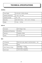
TECHNICAL SPECIFICATIONS GENERAL Power Supply Operating Temperature Operating Humidity Body Size Weight AC100-240V ~50/60Hz 40watts 0°~40°C / 32°~104°F 10% ~ 75% 394 X 259 X 47mm / 15.5" x 10.2" x 1.9"Inches 1.8 Kg / 3.97Lbs DISPLAY Illumination Backlighting Life Expectancy Resolution Screen CCFL Edge Lit Tube 10,000Hrs 1440(W) X 234(H) 7" TFT LCD (16:9) MISC TV Channels TV System Radio Frequency Range Audio output VHF/UHF (2-69), CABLE TV (STD,IRC,HRC) 1 - 125 NTSC AM 530KHz - 1710KHz FM 87.5MHz - 107.9MHz 1.2W / 8ohm (2 Speakers) 17-
TECHNICAL SPECIFICATIONS GENERAL Power Supply Operating Temperature Operating Humidity Body Size Weight AC100-240V ~50/60Hz 40watts 0°~40°C / 32°~104°F 10% ~ 75% 394 X 259 X 47mm / 15.5" x 10.2" x 1.9"Inches 1.8 Kg / 3.97Lbs DISPLAY Illumination Backlighting Life Expectancy Resolution Screen CCFL Edge Lit Tube 10,000Hrs 1440(W) X 234(H) 7" TFT LCD (16:9) MISC TV Channels TV System Radio Frequency Range Audio output VHF/UHF (2-69), CABLE TV (STD,IRC,HRC) 1 - 125 NTSC AM 530KHz - 1710KHz FM 87.5MHz - 107.9MHz 1.2W / 8ohm (2 Speakers) 17-

Operation Manual
Page 19
Try other system types with the instructions on the transmitter is not obstructed. • Check the condition of this manual. 18- Poor Reception Problem Remote control will not function Black and White Reception Solution • Verify Tuner setting matches Antenna/Cable broadcast system. • Verify that the sensor on the VE705 is not obstructed. • Verify that the infrared LED on page 14 of the remote control batteries. • Verify Tuner setting matches Antenna/Cable broadcast system.
Try other system types with the instructions on the transmitter is not obstructed. • Check the condition of this manual. 18- Poor Reception Problem Remote control will not function Black and White Reception Solution • Verify Tuner setting matches Antenna/Cable broadcast system. • Verify that the sensor on the VE705 is not obstructed. • Verify that the infrared LED on page 14 of the remote control batteries. • Verify Tuner setting matches Antenna/Cable broadcast system.


