Operation Manual
Page 1
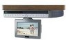
• Multi-function Remote Control • Cable Ready 125 Channel TV Tuner • Internal Stereo Speakers • Under Cabinet / Table Top Mounting • AM/FM Radio Tuner 0
• Multi-function Remote Control • Cable Ready 125 Channel TV Tuner • Internal Stereo Speakers • Under Cabinet / Table Top Mounting • AM/FM Radio Tuner 0

Operation Manual
Page 7
... Positioning the Screen 14 Setting the Time 14 Setting and Activating The Alarm 15 Deactivating Alarm 15 Setting the Alarm Tones 15 Setting the Cable TV Mode 15 Setting the Air TV Mode 16 Setting the Presets (For FM and AM or TV Modes 16 Technical Specifications 17 Troubleshooting Check List 18 6-
... Positioning the Screen 14 Setting the Time 14 Setting and Activating The Alarm 15 Deactivating Alarm 15 Setting the Alarm Tones 15 Setting the Cable TV Mode 15 Setting the Air TV Mode 16 Setting the Presets (For FM and AM or TV Modes 16 Technical Specifications 17 Troubleshooting Check List 18 6-
Operation Manual
Page 8
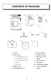
Mounting Hole Template 11. CONTENTS OF PACKAGE PWR T EL TV VOL M U TE CH ENT CH VOL SEEK A /V F M /A M 1 2 3 ER ASE 4 5 6 AD D 7 8 9 0 1. Right Angle Coaxial Adaptor 8. VE705 TV 2. Owners / Installation Manual 7 - Multi Height Spacer (4) 5. Foot (4) E. Battery (CR2025) 6. AM Antenna 10. Hole cap (4) 3. FM Dipole Antenna 7. FM Antenna Jack 9. Hardware bag A. 3/4" Mounting screws (4) B. 1-1/4" Mounting screws (4) C. 1-1/2"Mounting screws (4) D. Remote Control 4.
Mounting Hole Template 11. CONTENTS OF PACKAGE PWR T EL TV VOL M U TE CH ENT CH VOL SEEK A /V F M /A M 1 2 3 ER ASE 4 5 6 AD D 7 8 9 0 1. Right Angle Coaxial Adaptor 8. VE705 TV 2. Owners / Installation Manual 7 - Multi Height Spacer (4) 5. Foot (4) E. Battery (CR2025) 6. AM Antenna 10. Hole cap (4) 3. FM Dipole Antenna 7. FM Antenna Jack 9. Hardware bag A. 3/4" Mounting screws (4) B. 1-1/4" Mounting screws (4) C. 1-1/2"Mounting screws (4) D. Remote Control 4.
Operation Manual
Page 9
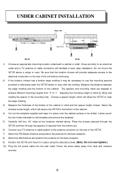
...outlet. The spacers and mounting holes are stepped to achieve different mounting heights from .5" to an electrical outlet and a TV antenna or cable connection will allow the VE705 to the antenna connector on the rear of the cabinet. Select the shortest screw length, which will facilitate a neat,...8243; holes at the locations marked above a range or oven. Measure the distance between the edge molding and the bottom of the VE705. 7) Attach the FM Dipole Antenna and position the antenna for the best reception. 8) Attach the AM Antenna and position the antenna for the best reception. ...
...outlet. The spacers and mounting holes are stepped to achieve different mounting heights from .5" to an electrical outlet and a TV antenna or cable connection will allow the VE705 to the antenna connector on the rear of the cabinet. Select the shortest screw length, which will facilitate a neat,...8243; holes at the locations marked above a range or oven. Measure the distance between the edge molding and the bottom of the VE705. 7) Attach the FM Dipole Antenna and position the antenna for the best reception. 8) Attach the AM Antenna and position the antenna for the best reception. ...

Operation Manual
Page 11
...P2 - Selected Preset Channel "3" in the Radio or TV mode. 13) P1- Selected Preset Channel "1" in the Radio or TV mode 11) P3 - BUTTON - Press and Hold this button to start the Auto Program feature. 6) TV BUTTON - please refer to change the aspect ratio. 7) FM BUTTON - Press this button to delete a selected ...channel. 5) AP BUTTON - FRONT PANEL CONTROLS 18 19 ON/OFF 12:00 SET ADD DEL AP TV FM AM CH SEEK VOLUME P1 P2 P3 P4 MUTE 1 9 2 10 3 11 4 12 5 13 6 14 7 15 8 16 17 19 1) ON/OFF BUTTON - ...
...P2 - Selected Preset Channel "3" in the Radio or TV mode. 13) P1- Selected Preset Channel "1" in the Radio or TV mode 11) P3 - BUTTON - Press and Hold this button to start the Auto Program feature. 6) TV BUTTON - please refer to change the aspect ratio. 7) FM BUTTON - Press this button to delete a selected ...channel. 5) AP BUTTON - FRONT PANEL CONTROLS 18 19 ON/OFF 12:00 SET ADD DEL AP TV FM AM CH SEEK VOLUME P1 P2 P3 P4 MUTE 1 9 2 10 3 11 4 12 5 13 6 14 7 15 8 16 17 19 1) ON/OFF BUTTON - ...

Operation Manual
Page 12
Allows the VE705 to be connected to an external antenna for the reception of AM broadcast signals. 4) TV ANTENNA (75 OHM ANTENNA CONNECTOR) -Allows the VE705 to be connected to a 75-Ohm external coaxial antenna for the reception of FM broadcast signals. 3) AM ANTENNA - hand held remote control unit. REAR PANEL CONNECTIONS 1 2 3 4 1) AC LINE CORD - Allows the VE705 to be connected to AC power outlet 2) FM ANTENNA - Connects to a 75-ohm external coaxial antenna or cable TV system. 11-
Allows the VE705 to be connected to an external antenna for the reception of AM broadcast signals. 4) TV ANTENNA (75 OHM ANTENNA CONNECTOR) -Allows the VE705 to be connected to a 75-Ohm external coaxial antenna for the reception of FM broadcast signals. 3) AM ANTENNA - hand held remote control unit. REAR PANEL CONNECTIONS 1 2 3 4 1) AC LINE CORD - Allows the VE705 to be connected to AC power outlet 2) FM ANTENNA - Connects to a 75-ohm external coaxial antenna or cable TV system. 11-
Operation Manual
Page 14
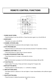
...UP/DOWN (W X) Press these buttons to change the TV aspect ratio. 9. FM/AM Each time this button to scan and store all active TV channels in memory. 5. POWER ON/OFF (PWR) Press this button is pressed, the VE705 will blink on display). 10. ENTER (ENT) ...turn the VE705 on the VE705 3. VOLUME UP/DOWN BUTTONS (TS) Press these buttons to advance to make a direct channel selection. 6. REMOTE CONTROL FUNCTIONS 6 7 PWR FM/AM TV 1 8 2 VOL MUTE CH ENT CH 9 3 VOL SEEK 10 4 A/P 1 2 3 DEL 11 5 4 5 6 ADD 12 7 8 9 0 1. TV BUTTON (TV) Used to select TV function,...
...UP/DOWN (W X) Press these buttons to change the TV aspect ratio. 9. FM/AM Each time this button to scan and store all active TV channels in memory. 5. POWER ON/OFF (PWR) Press this button is pressed, the VE705 will blink on display). 10. ENTER (ENT) ...turn the VE705 on the VE705 3. VOLUME UP/DOWN BUTTONS (TS) Press these buttons to advance to make a direct channel selection. 6. REMOTE CONTROL FUNCTIONS 6 7 PWR FM/AM TV 1 8 2 VOL MUTE CH ENT CH 9 3 VOL SEEK 10 4 A/P 1 2 3 DEL 11 5 4 5 6 ADD 12 7 8 9 0 1. TV BUTTON (TV) Used to select TV function,...

Operation Manual
Page 17
SETTING THE PRESETS (IN AM, FM OR TV MODES) 1) Tune the desired channel/station. 2) Press the SET button and the display flashes. 3) Press desired preset (P1, P2, P3 & P4) to confirm. SETTING THE AIR TV MODE 1) Press the SET button three times to enter the TV/Cable configuration mode. 2) Press the SEEK button to select the AIR mode. 3) Press the POWER button to confirm the selection. 16-
SETTING THE PRESETS (IN AM, FM OR TV MODES) 1) Tune the desired channel/station. 2) Press the SET button and the display flashes. 3) Press desired preset (P1, P2, P3 & P4) to confirm. SETTING THE AIR TV MODE 1) Press the SET button three times to enter the TV/Cable configuration mode. 2) Press the SEEK button to select the AIR mode. 3) Press the POWER button to confirm the selection. 16-
Operation Manual
Page 18
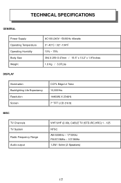
TECHNICAL SPECIFICATIONS GENERAL Power Supply Operating Temperature Operating Humidity Body Size Weight AC100-240V ~50/60Hz 40watts 0°~40°C / 32°~104°F 10% ~ 75% 394 X 259 X 47mm / 15.5" x 10.2" x 1.9"Inches 1.8 Kg / 3.97Lbs DISPLAY Illumination Backlighting Life Expectancy Resolution Screen CCFL Edge Lit Tube 10,000Hrs 1440(W) X 234(H) 7" TFT LCD (16:9) MISC TV Channels TV System Radio Frequency Range Audio output VHF/UHF (2-69), CABLE TV (STD,IRC,HRC) 1 - 125 NTSC AM 530KHz - 1710KHz FM 87.5MHz - 107.9MHz 1.2W / 8ohm (2 Speakers) 17-
TECHNICAL SPECIFICATIONS GENERAL Power Supply Operating Temperature Operating Humidity Body Size Weight AC100-240V ~50/60Hz 40watts 0°~40°C / 32°~104°F 10% ~ 75% 394 X 259 X 47mm / 15.5" x 10.2" x 1.9"Inches 1.8 Kg / 3.97Lbs DISPLAY Illumination Backlighting Life Expectancy Resolution Screen CCFL Edge Lit Tube 10,000Hrs 1440(W) X 234(H) 7" TFT LCD (16:9) MISC TV Channels TV System Radio Frequency Range Audio output VHF/UHF (2-69), CABLE TV (STD,IRC,HRC) 1 - 125 NTSC AM 530KHz - 1710KHz FM 87.5MHz - 107.9MHz 1.2W / 8ohm (2 Speakers) 17-


