Service Guide
Page 9
... installing or removing system components. 3. Chapter 2: Hardware setup This chapter lists the hardware setup procedures that comes with at least basic knowledge of the BIOS parameters are also provided. 6. This chapter includes the motherboard layout, jumper settings, and connector locations. 5. About this guide Audience This user guide is intended for system integrators and experienced users with the server. Chapter 6: Driver installation This chapter provides information on the front panel and rear panel specifications. 2. ix Chapter 4: Motherboard...
... installing or removing system components. 3. Chapter 2: Hardware setup This chapter lists the hardware setup procedures that comes with at least basic knowledge of the BIOS parameters are also provided. 6. This chapter includes the motherboard layout, jumper settings, and connector locations. 5. About this guide Audience This user guide is intended for system integrators and experienced users with the server. Chapter 6: Driver installation This chapter provides information on the front panel and rear panel specifications. 2. ix Chapter 4: Motherboard...
Service Guide
Page 13
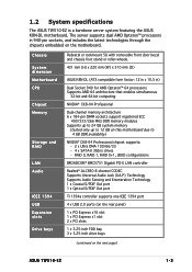
.../33 - 4 x SATA-II 3Gb/s drives - RAID 0, RAID 1, RAID 0+1, JBOD configurations BROADCOM® BMC5751 Gigabit PCI-E LAN controller Realtek® ALC850 8-channel CODEC Supports Universal Audio Jack (UAJ®) Technology Supports Audio Sensing and Enumeration Technology 1 x Coaxial S/PDIF Out port 1 x Optical S/PDIF Out port TI 1394a controller supports one IEEE 1394 port 4 x USB 2.0 ports (on the rear panel) 1 x PCI Express x16 slot 1 x PCI Express x1 slot 2 x PCI slots 1 x 3.25-inch FDD bay 3 x 5.25-inch drive bays (continued on the next page) ASUS TW510-E2 1-3
.../33 - 4 x SATA-II 3Gb/s drives - RAID 0, RAID 1, RAID 0+1, JBOD configurations BROADCOM® BMC5751 Gigabit PCI-E LAN controller Realtek® ALC850 8-channel CODEC Supports Universal Audio Jack (UAJ®) Technology Supports Audio Sensing and Enumeration Technology 1 x Coaxial S/PDIF Out port 1 x Optical S/PDIF Out port TI 1394a controller supports one IEEE 1394 port 4 x USB 2.0 ports (on the rear panel) 1 x PCI Express x16 slot 1 x PCI Express x1 slot 2 x PCI slots 1 x 3.25-inch FDD bay 3 x 5.25-inch drive bays (continued on the next page) ASUS TW510-E2 1-3
Service Guide
Page 15
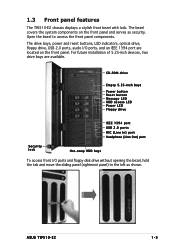
... installation of 5.25-inch devices, two drive bays are located on the front panel and serves as shown. 1.3 Front panel features The TW510-E2 chassis displays a stylish front bezel with lock. The drive bays, power and reset buttons, LED indicators, optical drive, floppy drive, USB 2.0 ports, audio I /O ports and floppy disk drive without opening the bezel, hold the tab and move the sliding panel (rightmost panel) to access the front panel components. CD-ROM drive Empty 5.25-inch bays Power button Reset button Message LED HDD access LED Power LED...
... installation of 5.25-inch devices, two drive bays are located on the front panel and serves as shown. 1.3 Front panel features The TW510-E2 chassis displays a stylish front bezel with lock. The drive bays, power and reset buttons, LED indicators, optical drive, floppy drive, USB 2.0 ports, audio I /O ports and floppy disk drive without opening the bezel, hold the tab and move the sliding panel (rightmost panel) to access the front panel components. CD-ROM drive Empty 5.25-inch bays Power button Reset button Message LED HDD access LED Power LED...
Service Guide
Page 37
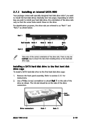
... correct orientation of the drive connectors. Remove the front panel assembly. Use a Phillips (cross) screwdriver to attach R a i l 1 to as "Rail 1" and "Rail 2" as shown. For identification purposes, the drive rails are referred to the side of the drive rails vary so that the screw holes match those on which bay you want to install the hard disk drives internally (not hot-swap...
... correct orientation of the drive connectors. Remove the front panel assembly. Use a Phillips (cross) screwdriver to attach R a i l 1 to as "Rail 1" and "Rail 2" as shown. For identification purposes, the drive rails are referred to the side of the drive rails vary so that the screw holes match those on which bay you want to install the hard disk drives internally (not hot-swap...
Service Guide
Page 43
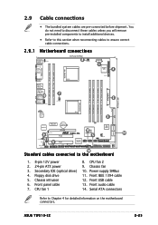
...CHASSIS1 FRNT_FAN2 SATA3 SATA4 10 Standard cables connected to Chapter 4 for detailed information on the motherboard connectors. Secondary IDE (optical drive) 4. CPU fan 1 8. Serial ATA connectors Refer to the motherboard 14 1. 8-pin 12V power 2. 24-pin ATX power 3. Front panel cable 7. Chassis fan 10. Power supply SMBus 11. Chassis intrusion 6. CPU fan 2 9. Front IEEE 1394 cable 12. Front audio cable 14. ASUS TW510-E2 2-25 Front USB cable 13. Floppy disk drive 5. 2.9 Cable connections • The bundled system cables are pre-connected before shipment.
...CHASSIS1 FRNT_FAN2 SATA3 SATA4 10 Standard cables connected to Chapter 4 for detailed information on the motherboard connectors. Secondary IDE (optical drive) 4. CPU fan 1 8. Serial ATA connectors Refer to the motherboard 14 1. 8-pin 12V power 2. 24-pin ATX power 3. Front panel cable 7. Chassis fan 10. Power supply SMBus 11. Chassis intrusion 6. CPU fan 2 9. Front IEEE 1394 cable 12. Front audio cable 14. ASUS TW510-E2 2-25 Front USB cable 13. Floppy disk drive 5. 2.9 Cable connections • The bundled system cables are pre-connected before shipment.
Service Guide
Page 44
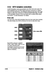
.... 2.9.2 SATA backplane connections A SATA backplane comes pre-installed in the TW510-E2 AA4 model. Refer to allow easy connection or removal of SATA hard disks. Front side The front side of the backplane. The backplane design incorporates a hot swap feature to the table for reference. The LED on the backplane connect to the front panel LED to support Serial ATA hard disk drives. The SATA backplane has four SATA signal and power connectors to indicate HDD...
.... 2.9.2 SATA backplane connections A SATA backplane comes pre-installed in the TW510-E2 AA4 model. Refer to allow easy connection or removal of SATA hard disks. Front side The front side of the backplane. The backplane design incorporates a hot swap feature to the table for reference. The LED on the backplane connect to the front panel LED to support Serial ATA hard disk drives. The SATA backplane has four SATA signal and power connectors to indicate HDD...
Service Guide
Page 46
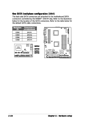
Refer to the table below for the default SATA cable connections. Backplane ID CON2 CON4 CON6 CON8 Connected to the motherboard SATA connectors controlled by the NVIDIA® CK8-04 chip. One SATA backplane configuration (AA4) The back side SATA connectors are attached to (on motherboard) SATA1 SATA2 SATA3 SATA4 SATA3 SATA4 NVIDIA CK8-04 Professional 4Mb BIOS USB56 USB78 CLRTC1 FRNT_FAN1 USB910 SATA1 SATA2 BPSMB1...
Refer to the table below for the default SATA cable connections. Backplane ID CON2 CON4 CON6 CON8 Connected to the motherboard SATA connectors controlled by the NVIDIA® CK8-04 chip. One SATA backplane configuration (AA4) The back side SATA connectors are attached to (on motherboard) SATA1 SATA2 SATA3 SATA4 SATA3 SATA4 NVIDIA CK8-04 Professional 4Mb BIOS USB56 USB78 CLRTC1 FRNT_FAN1 USB910 SATA1 SATA2 BPSMB1...

Service Guide
Page 68
... CLRTC jumper default position. Move the jumper cap from pins 1-2 (default) to overclocking, use the C.P.R. (CPU Parameter Recall) feature. Hold down and reboot the system so the BIOS can clear the CMOS memory of date, time, and system setup parameters by erasing the CMOS RTC RAM data. 4.2 Jumpers 1. To erase the RTC RAM: 1. Re-install the battery. 5. Plug the power cord and turn ON the computer. 6. Removing the cap will cause system boot failure! ®...
... CLRTC jumper default position. Move the jumper cap from pins 1-2 (default) to overclocking, use the C.P.R. (CPU Parameter Recall) feature. Hold down and reboot the system so the BIOS can clear the CMOS memory of date, time, and system setup parameters by erasing the CMOS RTC RAM data. 4.2 Jumpers 1. To erase the RTC RAM: 1. Re-install the battery. 5. Plug the power cord and turn ON the computer. 6. Removing the cap will cause system boot failure! ®...

Service Guide
Page 92
5.2 BIOS setup program This motherboard supports a programmable Low-Pin Count (LPC) chip that the computer can change the power management settings. When you start up the computer, the system provides you with its test routines. Being a menu-driven program, it as possible. For example, you scroll through the various sub-menus and make it lets you can also restart by pressing the reset button on . Press...
5.2 BIOS setup program This motherboard supports a programmable Low-Pin Count (LPC) chip that the computer can change the power management settings. When you start up the computer, the system provides you with its test routines. Being a menu-driven program, it as possible. For example, you scroll through the various sub-menus and make it lets you can also restart by pressing the reset button on . Press...

Service Guide
Page 93
... system configuration For changing the advanced system settings For changing the advanced power management (APM) configuration For changing the system boot configuration For selecting the exit options and loading default settings To select an item on the menu bar, press the right or left arrow key on the keyboard until the desired item is highlighted. ASUS TW510-E2 5-13 5.2.1 BIOS menu screen Menu items Menu bar Configuration fields General help Phoenix-Award BIOS CMOS Setup Utility Main Advanced Power Boot Exit...
... system configuration For changing the advanced system settings For changing the advanced power management (APM) configuration For changing the system boot configuration For selecting the exit options and loading default settings To select an item on the menu bar, press the right or left arrow key on the keyboard until the desired item is highlighted. ASUS TW510-E2 5-13 5.2.1 BIOS menu screen Menu items Menu bar Configuration fields General help Phoenix-Award BIOS CMOS Setup Utility Main Advanced Power Boot Exit...

Service Guide
Page 96
... Select Menu Item Specific Help Change the internal clock. F1:Help ESC: Exit ↑↓ : Select Item →←: Select Menu -/+: Change Value Enter: Select Sub-menu F5: Setup Defaults F10: Save and Exit 5.3.1 System Time [xx:xx:xx] Allows you to support Japanese standard floppy drives. Configuration options: [Disabled] [Drive A] 5.3.5 Base/Extended/Total Memory [xxxxxxK] The base memory, extended memory, and the total memory values are not user-configurable. 5-16 Chapter 5: BIOS setup
... Select Menu Item Specific Help Change the internal clock. F1:Help ESC: Exit ↑↓ : Select Item →←: Select Menu -/+: Change Value Enter: Select Sub-menu F5: Setup Defaults F10: Save and Exit 5.3.1 System Time [xx:xx:xx] Allows you to support Japanese standard floppy drives. Configuration options: [Disabled] [Drive A] 5.3.5 Base/Extended/Total Memory [xxxxxxK] The base memory, extended memory, and the total memory values are not user-configurable. 5-16 Chapter 5: BIOS setup

Service Guide
Page 97
... for supported IDE devices. Configuration options: [None] [Auto] [Manual] ASUS TW510-E2 5-17 These values are not user-configurable. The settings Mode 0 to automatically detect an IDE hard disk drive. While entering Setup, the BIOS automatically detects the presence of IDE devices. These items show "0" or "None" if no drive is installed in performance. If no IDE device is installed select [None]. PIO Mode Sets the PIO mode for each IDE device. Configuration options: [Auto] [Mode 0] [Mode 1] [Mode 2] [Mode 3] [Mode 4] UDMA Mode When this sub-menu...
... for supported IDE devices. Configuration options: [None] [Auto] [Manual] ASUS TW510-E2 5-17 These values are not user-configurable. The settings Mode 0 to automatically detect an IDE hard disk drive. While entering Setup, the BIOS automatically detects the presence of IDE devices. These items show "0" or "None" if no drive is installed in performance. If no IDE device is installed select [None]. PIO Mode Sets the PIO mode for each IDE device. Configuration options: [Auto] [Mode 0] [Mode 1] [Mode 2] [Mode 3] [Mode 4] UDMA Mode When this sub-menu...

Service Guide
Page 102
... Cool 'n' Quiet Control [Enabled] Disables or enables the AMD K8 Cool 'n' Quiet feature. Configuration options: [Disabled] [Enabled] 5.4.2 Memory Configuration This menu shows the memory configuration settings. Memclock Index Value (Mhz) [200MHz] Allows selection of the DRAM frequency. Select an item then press to set the DRAM timing configurations from the available options. Setting to [Manual] allows you to display a pop-up menu with the configuration options. Advanced Phoenix-Award BIOS CMOS Setup Utility Memory Configuration Timing Mode Memclock Index Value...
... Cool 'n' Quiet Control [Enabled] Disables or enables the AMD K8 Cool 'n' Quiet feature. Configuration options: [Disabled] [Enabled] 5.4.2 Memory Configuration This menu shows the memory configuration settings. Memclock Index Value (Mhz) [200MHz] Allows selection of the DRAM frequency. Select an item then press to set the DRAM timing configurations from the available options. Setting to [Manual] allows you to display a pop-up menu with the configuration options. Advanced Phoenix-Award BIOS CMOS Setup Utility Memory Configuration Timing Mode Memclock Index Value...

Service Guide
Page 112
... install high speed USB devices. Setting this item to [Enabled] allows the built-in high speed USB support in the BIOS to turn on automatically when you to enable or disable the USB controller. Configuration options: [Disabled] [Enabled] 5-32 Chapter 5: BIOS setup Select an item then press to enable or disable support for the legacy USB devices. Configuration options: [Disabled] [Enabled] USB Legacy Mode Support [Enabled] Allows you to enable or disable the USB 2.0 controller. Advanced Phoenix-Award BIOS CMOS Setup Utility USB Configuration Select Menu USB Controller...
... install high speed USB devices. Setting this item to [Enabled] allows the built-in high speed USB support in the BIOS to turn on automatically when you to enable or disable the USB controller. Configuration options: [Disabled] [Enabled] 5-32 Chapter 5: BIOS setup Select an item then press to enable or disable support for the legacy USB devices. Configuration options: [Disabled] [Enabled] USB Legacy Mode Support [Enabled] Allows you to enable or disable the USB 2.0 controller. Advanced Phoenix-Award BIOS CMOS Setup Utility USB Configuration Select Menu USB Controller...

Service Guide
Page 114
... set the automatic power saving features. 5.5.1 APM Configuration This menu shows the Advanced Powed Management (APM) configuration settings. Configuration options: [Disabled] [1 Min] [2 Min]... [15 Min] Video Off Method [DPMS Support] Allows you press the power button for more than 4 seconds. Phoenix-Award BIOS CMOS Setup Utility Main Advanced Power Boot Exit APM Configuration Select Menu Power Management HDD Power Down Video Off Method Soft-Off by PBTN Restore on AC Power Loss Power On By PCI Devices WOR(RI#) From Soft-Off USB Wake...
... set the automatic power saving features. 5.5.1 APM Configuration This menu shows the Advanced Powed Management (APM) configuration settings. Configuration options: [Disabled] [1 Min] [2 Min]... [15 Min] Video Off Method [DPMS Support] Allows you press the power button for more than 4 seconds. Phoenix-Award BIOS CMOS Setup Utility Main Advanced Power Boot Exit APM Configuration Select Menu Power Management HDD Power Down Video Off Method Soft-Off by PBTN Restore on AC Power Loss Power On By PCI Devices WOR(RI#) From Soft-Off USB Wake...

Service Guide
Page 119
... Select Item →←: Select Menu -/+: Change Value Enter: Select Sub-menu F5: Setup Defaults F10: Save and Exit 5.6.1 Boot Device Priority Phoenix-Award BIOS CMOS Setup Utility Main Advanced Power Boot Exit Boot Device Priority Select Menu 1st Boot Device 2nd Boot Device 3rd Boot Device [Removable] [CDROM] [Hard Disk] Item Specific Help Select your boot device priority. Configuration options: [Removable] [Hard Disk] [CDROM] [Legacy LAN] [Disabled] ASUS TW510-E2 5-39 5.6 Boot menu The Boot menu items allow you to select your boot device priority F1:Help ESC: Exit ↑...
... Select Item →←: Select Menu -/+: Change Value Enter: Select Sub-menu F5: Setup Defaults F10: Save and Exit 5.6.1 Boot Device Priority Phoenix-Award BIOS CMOS Setup Utility Main Advanced Power Boot Exit Boot Device Priority Select Menu 1st Boot Device 2nd Boot Device 3rd Boot Device [Removable] [CDROM] [Hard Disk] Item Specific Help Select your boot device priority. Configuration options: [Removable] [Hard Disk] [CDROM] [Legacy LAN] [Disabled] ASUS TW510-E2 5-39 5.6 Boot menu The Boot menu items allow you to select your boot device priority F1:Help ESC: Exit ↑...

Service Guide
Page 123
... BIOS CMOS Setup Utility Main Advanced Power Boot Exit Security Select Menu Supervisor Password User Password Password Check Clear Clear [Setup] Item Specific Help Select your boot device priority. The password field setting is changed to S e t. Press any key to continue. To clear the password: 1. Select an item then press . 2. Press any key to continue... 2. ASUS TW510-E2 5-43 Type in a password using a combination of a maximum of eight (8) alpha-numeric characters, then press . 3. The password field setting is changed to set passwords: To set a password...
... BIOS CMOS Setup Utility Main Advanced Power Boot Exit Security Select Menu Supervisor Password User Password Password Check Clear Clear [Setup] Item Specific Help Select your boot device priority. The password field setting is changed to S e t. Press any key to continue. To clear the password: 1. Select an item then press . 2. Press any key to continue... 2. ASUS TW510-E2 5-43 Type in a password using a combination of a maximum of eight (8) alpha-numeric characters, then press . 3. The password field setting is changed to set passwords: To set a password...

Service Guide
Page 129
... RAID configurations. 6.1.2 RAID configuration utility You can create a RAID set using the utility embedded in each drive. For optimal performance, install identical drives of each drive. Refer to the RAID controllers user manual on the support CD for details on how to the power connector on each hard disk as Master/Master or Slave/Slave. 2. Connect a 4-pin power cable to enter the RAID configuration utility. 6.1.1 Installing hard disks The motherboard supports Ultra DMA 100/66 IDE and Serial ATA hard disk drives. ASUS TW510-E2 6-3 Set the jumpers of the same model...
... RAID configurations. 6.1.2 RAID configuration utility You can create a RAID set using the utility embedded in each drive. For optimal performance, install identical drives of each drive. Refer to the RAID controllers user manual on the support CD for details on how to the power connector on each hard disk as Master/Master or Slave/Slave. 2. Connect a 4-pin power cable to enter the RAID configuration utility. 6.1.1 Installing hard disks The motherboard supports Ultra DMA 100/66 IDE and Serial ATA hard disk drives. ASUS TW510-E2 6-3 Set the jumpers of the same model...

Service Guide
Page 130
... your screen. Enter the BIOS Setup during POST. 2. Go to set the BIOS RAID items: 1. Setting the BIOS RAID items After installing the hard disk drives, make sure to the A d v a n c e d menu, select O n b o a r d D e v i c e, then press . 3. Restart the computer. 2. NVIDIA RAID Utility Oct 5 2004 - Select [ E n a b l e d ] from the options, then press . 6. Select the N V R A I D E n a b l e d item, then press to display the configuration options. 5. Define a New Array - 6.1.3 NVIDIA® RAID configurations The motherboard includes a high performance SATA RAID controller...
... your screen. Enter the BIOS Setup during POST. 2. Go to set the BIOS RAID items: 1. Setting the BIOS RAID items After installing the hard disk drives, make sure to the A d v a n c e d menu, select O n b o a r d D e v i c e, then press . 3. Restart the computer. 2. NVIDIA RAID Utility Oct 5 2004 - Select [ E n a b l e d ] from the options, then press . 6. Select the N V R A I D E n a b l e d item, then press to display the configuration options. 5. Define a New Array - 6.1.3 NVIDIA® RAID configurations The motherboard includes a high performance SATA RAID controller...

Service Guide
Page 161
... or disk error" appears 2. Make sure that you installed on supported DIMMs. 2. Make sure that the network cable is active. s y s t e m 1. Problem Action T h e s y s t e m c o n t i n u o u s l y 1. Make sure that the DIMMs are properly installed. ASUS TW510-E2 A-5 Check the memory modules beeps after it was turned and make sure you have installed the LAN drivers from the support CD. T h e m e s s a g e " N o n - Check if a bootable HDD is connected to the LAN port on the sockets. Check if the HDDs are properly installed on the rear panel. 2. Network...
... or disk error" appears 2. Make sure that you installed on supported DIMMs. 2. Make sure that the network cable is active. s y s t e m 1. Problem Action T h e s y s t e m c o n t i n u o u s l y 1. Make sure that the DIMMs are properly installed. ASUS TW510-E2 A-5 Check the memory modules beeps after it was turned and make sure you have installed the LAN drivers from the support CD. T h e m e s s a g e " N o n - Check if a bootable HDD is connected to the LAN port on the sockets. Check if the HDDs are properly installed on the rear panel. 2. Network...


