
User Manual
Page 1
P8P67-M PRO Motherboard
P8P67-M PRO Motherboard
User Manual
Page 3
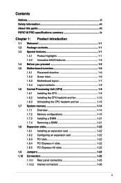
Contents Notices...vi Safety information vii About this guide vii P8P67-M PRO specifications summary ix Chapter 1: Product introduction 1.1 Welcome 1-1 1.2 Package contents 1-1 1.3 Special features 1-1 1.3.1 Product highlights 1-1 1.3.2 Innovative ASUS features 1-3 1.4 Before you proceed 1-5 1.5 Motherboard overview 1-6 1.5.1 Placement direction 1-6 1.5.2 Screw holes 1-6 1.5.3 Motherboard layout 1-7 1.5.4 Layout contents 1-8 1.6 Central Processing Unit (CPU 1-9 1.6.1 Installing the CPU 1-9 1.6.2 Installing the CPU heatsink and fan 1-12 1.6.3 Uninstalling...
Contents Notices...vi Safety information vii About this guide vii P8P67-M PRO specifications summary ix Chapter 1: Product introduction 1.1 Welcome 1-1 1.2 Package contents 1-1 1.3 Special features 1-1 1.3.1 Product highlights 1-1 1.3.2 Innovative ASUS features 1-3 1.4 Before you proceed 1-5 1.5 Motherboard overview 1-6 1.5.1 Placement direction 1-6 1.5.2 Screw holes 1-6 1.5.3 Motherboard layout 1-7 1.5.4 Layout contents 1-8 1.6 Central Processing Unit (CPU 1-9 1.6.1 Installing the CPU 1-9 1.6.2 Installing the CPU heatsink and fan 1-12 1.6.3 Uninstalling...
User Manual
Page 6
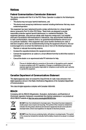
.... Notices Federal Communications Commission Statement This device complies with Canadian ICES-003. REACH Complying with FCC regulations. DO NOT throw the motherboard in our products at ASUS REACH website at http://csr.asus.com/english/REACH.htm. This symbol of the crossed out wheeled bin indicates that the product (electrical and electronic equipment...
.... Notices Federal Communications Commission Statement This device complies with Canadian ICES-003. REACH Complying with FCC regulations. DO NOT throw the motherboard in our products at ASUS REACH website at http://csr.asus.com/english/REACH.htm. This symbol of the crossed out wheeled bin indicates that the product (electrical and electronic equipment...
User Manual
Page 7
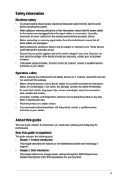
... electrical outlet you are unplugged. • Seek professional assistance before using an adapter or extension cord. Detailed descriptions of the motherboard and the new technology it supports. • Chapter 2: BIOS information This chapter tells how to fix it , carefully read... 1: Product introduction This chapter describes the features of the BIOS parameters are connected. If you need when installing and configuring the motherboard. If possible, disconnect all power cables from the existing system before you encounter technical problems with the package. • Before ...
... electrical outlet you are unplugged. • Seek professional assistance before using an adapter or extension cord. Detailed descriptions of the motherboard and the new technology it supports. • Chapter 2: BIOS information This chapter tells how to fix it , carefully read... 1: Product introduction This chapter describes the features of the BIOS parameters are connected. If you need when installing and configuring the motherboard. If possible, disconnect all power cables from the existing system before you encounter technical problems with the package. • Before ...
User Manual
Page 13
... damaged or missing, contact your motherboard package for buying an ASUS® P8P67-M PRO motherboard! Chapter 1: Product introduction 1-1 Before you for the following items. Motherboard Cables Accessories Application DVD Documentation ASUS P8P67-M PRO motherboard 2 x Serial ATA 3.0Gb/s cables 2 x Serial ATA 6.0Gb/s cables 1 x Q-shield 1 x Q-Connector (retail version only) ASUS motherboard support DVD User Manual If any of ASUS quality motherboards! This provides great graphics performance...
... damaged or missing, contact your motherboard package for buying an ASUS® P8P67-M PRO motherboard! Chapter 1: Product introduction 1-1 Before you for the following items. Motherboard Cables Accessories Application DVD Documentation ASUS P8P67-M PRO motherboard 2 x Serial ATA 3.0Gb/s cables 2 x Serial ATA 6.0Gb/s cables 1 x Q-shield 1 x Q-Connector (retail version only) ASUS motherboard support DVD User Manual If any of ASUS quality motherboards! This provides great graphics performance...
User Manual
Page 14
... connecor at double the bandwidth of current bus systems. Dual-Channel DDR3 2200(O.C.) / 2133(O.C.) / 1866(O.C.) / 1600(O.C.) / 1333 / 1066MHz support The motherboard supports DDR3 memory that features data transfer rates of 2200(O.C.) / 2133(O.C.) / 1866(O.C.) / 1600(O.C.) / 1333 / 1066 MHz to boost system performance. ...double the bandwidth of your system memory to meet the higher bandwidth requirements of Line-in, Line-out, and Mic jacks. 1-2 ASUS P8P67-M PRO Intel® P67 Express Chipset The Intel® P67 Express Chipset is also backward compatible with USB 3.0 - Built to -point...
... connecor at double the bandwidth of current bus systems. Dual-Channel DDR3 2200(O.C.) / 2133(O.C.) / 1866(O.C.) / 1600(O.C.) / 1333 / 1066MHz support The motherboard supports DDR3 memory that features data transfer rates of 2200(O.C.) / 2133(O.C.) / 1866(O.C.) / 1600(O.C.) / 1333 / 1066 MHz to boost system performance. ...double the bandwidth of your system memory to meet the higher bandwidth requirements of Line-in, Line-out, and Mic jacks. 1-2 ASUS P8P67-M PRO Intel® P67 Express Chipset The Intel® P67 Express Chipset is also backward compatible with USB 3.0 - Built to -point...
User Manual
Page 15
... efficient power management for advanced operating systems. 100% All High-quality Conductive Polymer Capacitors This motherboard uses all high-quality conductive polymer capacitors for durability, improved lifespan, and enhanced thermal capacity. Innovative ASUS features ASUS EFI BIOS (EZ Mode) ASUS brand new EFI BIOS offers a user-friendly interface that demand far more flexible and...
... efficient power management for advanced operating systems. 100% All High-quality Conductive Polymer Capacitors This motherboard uses all high-quality conductive polymer capacitors for durability, improved lifespan, and enhanced thermal capacity. Innovative ASUS features ASUS EFI BIOS (EZ Mode) ASUS brand new EFI BIOS offers a user-friendly interface that demand far more flexible and...

User Manual
Page 16
... restore a corrupted BIOS file using the bundled support DVD or USB flash disk that contains the latest BIOS file. 1-4 ASUS P8P67-M PRO ASUS CrashFree BIOS 3 ASUS CrashFree BIOS 3 is an auto-recovery tool that allows you to supervise overclocking, energy management, fan speed control, and ...PC's loading. beginners can achieve extreme yet stable overclocking results with the elegant appearance! ASUS Anti-Surge Protection This special design prevents expensive devices and the motherboard from switching power supply (PSU). The beautifully curved fins not only upgrade the visual ...
... restore a corrupted BIOS file using the bundled support DVD or USB flash disk that contains the latest BIOS file. 1-4 ASUS P8P67-M PRO ASUS CrashFree BIOS 3 ASUS CrashFree BIOS 3 is an auto-recovery tool that allows you to supervise overclocking, energy management, fan speed control, and ...PC's loading. beginners can achieve extreme yet stable overclocking results with the elegant appearance! ASUS Anti-Surge Protection This special design prevents expensive devices and the motherboard from switching power supply (PSU). The beautifully curved fins not only upgrade the visual ...
User Manual
Page 17
eliminates the need to energy consumptions. ErP ready The motherboard is European Union´s Energy-related Products (ErP) ready, and ErP requires products to meet certain energy efficiency requirements in the bag that came with ASUS vision of creating environment-friendly and energy-efficient products through...BIOS without using an OS-based utility. ASUS EZ Flash 2 ASUS EZ Flash 2 is a utility that the ATX power supply is switched off or the power cord is detached from the wall socket before you install motherboard components or change any motherboard settings. • Unplug the power ...
eliminates the need to energy consumptions. ErP ready The motherboard is European Union´s Energy-related Products (ErP) ready, and ErP requires products to meet certain energy efficiency requirements in the bag that came with ASUS vision of creating environment-friendly and energy-efficient products through...BIOS without using an OS-based utility. ASUS EZ Flash 2 ASUS EZ Flash 2 is a utility that the ATX power supply is switched off or the power cord is detached from the wall socket before you install motherboard components or change any motherboard settings. • Unplug the power ...

User Manual
Page 18
.... Failure to the chassis. Doing so can cause you physical injury and damage motherboard components. 1.5.1 Placement direction When installing the motherboard, ensure that you install the motherboard, study the configuration of the chassis P8P67-M PRO 1-6 ASUS P8P67-M PRO 1.5 Motherboard overview Before you place it . Ensure that the motherboard fits into it into the chassis in the image below. 1.5.2 Screw holes...
.... Failure to the chassis. Doing so can cause you physical injury and damage motherboard components. 1.5.1 Placement direction When installing the motherboard, ensure that you install the motherboard, study the configuration of the chassis P8P67-M PRO 1-6 ASUS P8P67-M PRO 1.5 Motherboard overview Before you place it . Ensure that the motherboard fits into it into the chassis in the image below. 1.5.2 Screw holes...
User Manual
Page 21
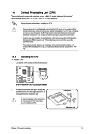
...incorrect CPU installation/removal, or misplacement/loss/incorrect removal of the PnP cap. 1.6.1 Installing the CPU To install a CPU: 1. P8P67-M PRO P8P67-M PRO CPU socket LGA1155 2. To prevent damage to the socket contacts resulting from the retention tab. Press the load lever with your ... and then move it is shipment/transit-related. • Keep the cap after installing the motherboard. ASUS will shoulder the cost of the motherboard, ensure that the PnP cap is on the motherboard. Load lever A B Retention tab Chapter 1: Product introduction 1-9 Locate the CPU socket on ...
...incorrect CPU installation/removal, or misplacement/loss/incorrect removal of the PnP cap. 1.6.1 Installing the CPU To install a CPU: 1. P8P67-M PRO P8P67-M PRO CPU socket LGA1155 2. To prevent damage to the socket contacts resulting from the retention tab. Press the load lever with your ... and then move it is shipment/transit-related. • Keep the cap after installing the motherboard. ASUS will shoulder the cost of the motherboard, ensure that the PnP cap is on the motherboard. Load lever A B Retention tab Chapter 1: Product introduction 1-9 Locate the CPU socket on ...
User Manual
Page 24
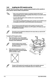
... properly applied Thermal Interface Material to the CPU fan connector. 2. Place the heatsink on the motherboard. The illustration above is incompatible with the LGA775 and LGA1366 sockets in a diagonal sequence to the...includes the CPU fan and heatsink assembly. B B Orient the heatsink and fan assembly A such that you have installed the motherboard to secure the heatsink and fan assembly in a push-pin design and requires no tool to ensure optimum thermal condition and ...CPU heatsink and fan assembly only. The LGA1155 socket is for reference only. 1-12 ASUS P8P67-M PRO
... properly applied Thermal Interface Material to the CPU fan connector. 2. Place the heatsink on the motherboard. The illustration above is incompatible with the LGA775 and LGA1366 sockets in a diagonal sequence to the...includes the CPU fan and heatsink assembly. B B Orient the heatsink and fan assembly A such that you have installed the motherboard to secure the heatsink and fan assembly in a push-pin design and requires no tool to ensure optimum thermal condition and ...CPU heatsink and fan assembly only. The LGA1155 socket is for reference only. 1-12 ASUS P8P67-M PRO
User Manual
Page 25
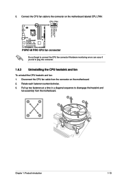
... CPU FAN PWR GND P8P67-M PRO P8P67-M PRO CPU fan connector Do not forget to plug this connector. 1.6.3 Uninstalling the CPU heatsink and fan To uninstall the CPU heatsink and fan: 1. Pull up two fasteners at a time in a diagonal sequence to the connector on the motherboard. 2. A B A... B B A B A Chapter 1: Product introduction 1-13 Disconnect the CPU fan cable from the motherboard. Rotate each fastener counterclockwise. 3. Connect the CPU fan cable to disengage the ...
... CPU FAN PWR GND P8P67-M PRO P8P67-M PRO CPU fan connector Do not forget to plug this connector. 1.6.3 Uninstalling the CPU heatsink and fan To uninstall the CPU heatsink and fan: 1. Pull up two fasteners at a time in a diagonal sequence to the connector on the motherboard. 2. A B A... B B A B A Chapter 1: Product introduction 1-13 Disconnect the CPU fan cable from the motherboard. Rotate each fastener counterclockwise. 3. Connect the CPU fan cable to disengage the ...
User Manual
Page 26
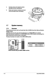
... sockets: DIMM_A1 DIMM_A2 DIMM_B1 DIMM_B2 P8P67-M PRO Channel Channel A Channel B Sockets DIMM_A1 and DIMM_A2 DIMM_B1 and DIMM_B2 P8P67-M PRO 240-pin DDR3 DIMM sockets 1-14 ASUS P8P67-M PRO A DDR3 module has the same physical dimensions as a DDR2 DIMM but is notched differently to ensure correct orientation when reinstalling. 1.7 System memory 1.7.1 Overview The motherboard comes with less power consumption...
... sockets: DIMM_A1 DIMM_A2 DIMM_B1 DIMM_B2 P8P67-M PRO Channel Channel A Channel B Sockets DIMM_A1 and DIMM_A2 DIMM_B1 and DIMM_B2 P8P67-M PRO 240-pin DDR3 DIMM sockets 1-14 ASUS P8P67-M PRO A DDR3 module has the same physical dimensions as a DDR2 DIMM but is notched differently to ensure correct orientation when reinstalling. 1.7 System memory 1.7.1 Overview The motherboard comes with less power consumption...
User Manual
Page 27
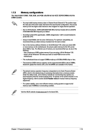
... • Due to the memory address limitation on 32-bit Windows® OS, when you install 4GB or more memory on the motherboard. • This motherboard does not support DIMMs made up of the lower-sized channel for the dual-channel configuration. Under the default state, some memory modules for.../1800 MHz memory module will update the memory QVL once the DIMMs are using a 32-bit Windows® OS. - Visit the ASUS website at www.asus.com for overclocking may install varying memory sizes in the market. • The default memory operation frequency is dependent on its Serial Presence...
... • Due to the memory address limitation on 32-bit Windows® OS, when you install 4GB or more memory on the motherboard. • This motherboard does not support DIMMs made up of the lower-sized channel for the dual-channel configuration. Under the default state, some memory modules for.../1800 MHz memory module will update the memory QVL once the DIMMs are using a 32-bit Windows® OS. - Visit the ASUS website at www.asus.com for overclocking may install varying memory sizes in the market. • The default memory operation frequency is dependent on its Serial Presence...
User Manual
Page 33
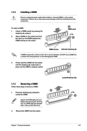
... the socket. 2 DIMM notch 1 DIMM slot key Unlocked retaining clip A DIMM is properly seated. 3 Locked Retaining Clip 1.7.4 Removing a DIMM Follow these steps to both the motherboard and the components. DO NOT force a DIMM into the socket until the retaining clip snaps back in the wrong direction to avoid damaging the DIMM...
... the socket. 2 DIMM notch 1 DIMM slot key Unlocked retaining clip A DIMM is properly seated. 3 Locked Retaining Clip 1.7.4 Removing a DIMM Follow these steps to both the motherboard and the components. DO NOT force a DIMM into the socket until the retaining clip snaps back in the wrong direction to avoid damaging the DIMM...
User Manual
Page 34
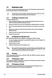
...the expansion card, read the documentation that came with the screw you removed earlier. 6. Remove the system unit cover (if your motherboard is completely seated on shared slots, ensure that the drivers support "Share IRQ" or that support PCI Express x16 2.0 graphic ...injury and damage motherboard components. 1.8.1 Installing an expansion card To install an expansion card: 1. Unplug the power cord before adding or removing expansion cards. Keep the screw for the expansion card. Align the card connector with the PCI Express specifications. 1-22 ASUS P8P67-M PRO Turn on BIOS ...
...the expansion card, read the documentation that came with the screw you removed earlier. 6. Remove the system unit cover (if your motherboard is completely seated on shared slots, ensure that the drivers support "Share IRQ" or that support PCI Express x16 2.0 graphic ...injury and damage motherboard components. 1.8.1 Installing an expansion card To install an expansion card: 1. Unplug the power cord before adding or removing expansion cards. Keep the screw for the expansion card. Align the card connector with the PCI Express specifications. 1-22 ASUS P8P67-M PRO Turn on BIOS ...
User Manual
Page 35
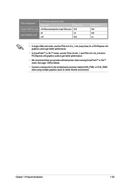
... performance. • In CrossFireX™ or SLI™ mode, use the PCIe 2.0 x16_1 and PCIe 2.0 x16_2 slots for PCI Express x16 graphics cards to the motherboard connector labeled CHA_FAN1 or CHA_FAN2 when using multiple graphics cards for details. • Connect a chassis fan to get better performance. • We recommend that you...
... performance. • In CrossFireX™ or SLI™ mode, use the PCIe 2.0 x16_1 and PCIe 2.0 x16_2 slots for PCI Express x16 graphics cards to the motherboard connector labeled CHA_FAN1 or CHA_FAN2 when using multiple graphics cards for details. • Connect a chassis fan to get better performance. • We recommend that you...
User Manual
Page 39
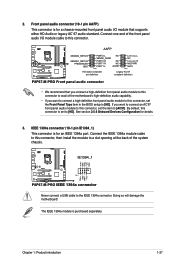
... standard. IEEE 1394a connector (10-1 pin IE1394_1) This connector is purchased separately. Doing so will damage the motherboard! IE1394_1 TPA1GND TPB1+12V GND P8P67-M PRO PIN 1 TPA1+ GND TPB1+ +12V P8P67-M PRO IEEE 1394a connector Never connect a USB cable to [HD]. The IEEE 1394a module is for an IEEE 1394a... 3. By default, this connector, set the Front Panel Type item in the BIOS setup to a slot opening at the back of the motherboard's high-definition audio capability. • If you want to connect an AC'97 front panel audio module to this connector, set to the...
... standard. IEEE 1394a connector (10-1 pin IE1394_1) This connector is purchased separately. Doing so will damage the motherboard! IE1394_1 TPA1GND TPB1+12V GND P8P67-M PRO PIN 1 TPA1+ GND TPB1+ +12V P8P67-M PRO IEEE 1394a connector Never connect a USB cable to [HD]. The IEEE 1394a module is for an IEEE 1394a... 3. By default, this connector, set the Front Panel Type item in the BIOS setup to a slot opening at the back of the motherboard's high-definition audio capability. • If you want to connect an AC'97 front panel audio module to this connector, set to the...
User Manual
Page 41
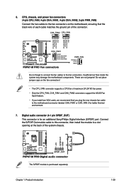
...CPU FAN PWM P8P67-M PRO Fan connectors PWR_FAN Rotation +12V GND Do not forget to connect the fan cables to a slot opening at the back of maximum 2A (24 W) fan power. • Only the CPU_FAN, CHA_FAN1 and CHA_FAN2 connectors support the ASUS Fan Xpert feature...system chassis. +5V SPDIFOUT GND P8P67-M PRO SPDIF_OUT P8P67-M PRO Digital audio connector The S/PDIF module is for better thermal environment. 7. CPU, chassis, and power fan connectors (4-pin CPU_FAN, 4-pin CHA_FAN1, 4-pin CHA_FAN2, 3-pin PWR_FAN) Connect the fan cables to the motherboard connector labeled CHA_FAN1 or CAH_FAN ...
...CPU FAN PWM P8P67-M PRO Fan connectors PWR_FAN Rotation +12V GND Do not forget to connect the fan cables to a slot opening at the back of maximum 2A (24 W) fan power. • Only the CPU_FAN, CHA_FAN1 and CHA_FAN2 connectors support the ASUS Fan Xpert feature...system chassis. +5V SPDIFOUT GND P8P67-M PRO SPDIF_OUT P8P67-M PRO Digital audio connector The S/PDIF module is for better thermal environment. 7. CPU, chassis, and power fan connectors (4-pin CPU_FAN, 4-pin CHA_FAN1, 4-pin CHA_FAN2, 3-pin PWR_FAN) Connect the fan cables to the motherboard connector labeled CHA_FAN1 or CAH_FAN ...


