User Manual
Page 13
... PCI Express 2.0 lanes. Chapter 1: Product introduction 1-1 Before you for the following items. Motherboard Cables Accessories Application DVD Documentation ASUS P8P67-M PRO motherboard 2 x Serial ATA 3.0Gb/s cables 2 x Serial ATA 6.0Gb/s cables 1 x Q-shield 1 x Q-Connector (retail version only) ASUS motherboard support DVD User Manual If any of new features and latest technologies, making it , check the items...
... PCI Express 2.0 lanes. Chapter 1: Product introduction 1-1 Before you for the following items. Motherboard Cables Accessories Application DVD Documentation ASUS P8P67-M PRO motherboard 2 x Serial ATA 3.0Gb/s cables 2 x Serial ATA 6.0Gb/s cables 1 x Q-shield 1 x Q-Connector (retail version only) ASUS motherboard support DVD User Manual If any of new features and latest technologies, making it , check the items...
User Manual
Page 14
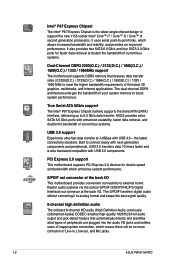
...-PHILIPS Digital Interface) out connecor at the back I /O. ASUS provides extra SATA 6.0 Gb/s ports with enhanced scalability, faster data retrieval, and double the bandwidth of your system memory to meet the higher bandwidth requirements of Line-in, Line-out, and Mic jacks. 1-2 ASUS P8P67-M PRO S/PDIF out connector at the back I /O This motherboard provides...
...-PHILIPS Digital Interface) out connecor at the back I /O. ASUS provides extra SATA 6.0 Gb/s ports with enhanced scalability, faster data retrieval, and double the bandwidth of your system memory to meet the higher bandwidth requirements of Line-in, Line-out, and Mic jacks. 1-2 ASUS P8P67-M PRO S/PDIF out connector at the back I /O This motherboard provides...

User Manual
Page 16
... elegant appearance! Fanless Design: stylish heatsink solution The Wing Heatsink features a 0-dB thermal solution that contains the latest BIOS file. 1-4 ASUS P8P67-M PRO The beautifully curved fins not only upgrade the visual enjoyment for a more colorful and vivid image on your screen. The built-in variety... of useful profiles offer flexible controls of fan speed to switch back and forth between different utilities. ASUS CrashFree BIOS 3 ASUS CrashFree BIOS 3 is an auto-recovery tool that allows you to adjust the CPU and chassis fan speeds according to different...
... elegant appearance! Fanless Design: stylish heatsink solution The Wing Heatsink features a 0-dB thermal solution that contains the latest BIOS file. 1-4 ASUS P8P67-M PRO The beautifully curved fins not only upgrade the visual enjoyment for a more colorful and vivid image on your screen. The built-in variety... of useful profiles offer flexible controls of fan speed to switch back and forth between different utilities. ASUS CrashFree BIOS 3 ASUS CrashFree BIOS 3 is an auto-recovery tool that allows you to adjust the CPU and chassis fan speeds according to different...

User Manual
Page 18
... external ports goes to the rear part of the chassis as indicated in the correct orientation. Place this side towards the rear of the chassis P8P67-M PRO 1-6 ASUS P8P67-M PRO Do not overtighten the screws! Doing so can cause you physical injury and damage motherboard components. 1.5.1 Placement direction When installing the motherboard, ensure that you...
... external ports goes to the rear part of the chassis as indicated in the correct orientation. Place this side towards the rear of the chassis P8P67-M PRO 1-6 ASUS P8P67-M PRO Do not overtighten the screws! Doing so can cause you physical injury and damage motherboard components. 1.5.1 Placement direction When installing the motherboard, ensure that you...
User Manual
Page 22
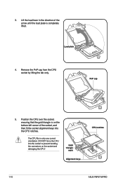
... one correct orientation. Position the CPU over the socket, ensuring that the gold triangle is completely lifted. Gold triangle mark Alignment keys CPU notches 1-10 ASUS P8P67-M PRO Load plate 4. DO NOT force the CPU into the CPU notches. 3.
... one correct orientation. Position the CPU over the socket, ensuring that the gold triangle is completely lifted. Gold triangle mark Alignment keys CPU notches 1-10 ASUS P8P67-M PRO Load plate 4. DO NOT force the CPU into the CPU notches. 3.
User Manual
Page 24
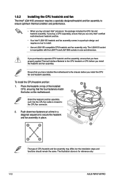
... and heatsink assembly. Push down two fasteners at a time in a diagonal sequence to the CPU fan connector. 2. The LGA1155 socket is for reference only. 1-12 ASUS P8P67-M PRO To install the CPU heatsink and fan: A 1. A B 1 1 B A The type of the installed CPU, ensuring that the four fasteners match the holes on top of CPU...
... and heatsink assembly. Push down two fasteners at a time in a diagonal sequence to the CPU fan connector. 2. The LGA1155 socket is for reference only. 1-12 ASUS P8P67-M PRO To install the CPU heatsink and fan: A 1. A B 1 1 B A The type of the installed CPU, ensuring that the four fasteners match the holes on top of CPU...
User Manual
Page 26
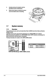
.... 1.7 System memory 1.7.1 Overview The motherboard comes with less power consumption. The figure illustrates the location of the DDR3 DIMM sockets: DIMM_A1 DIMM_A2 DIMM_B1 DIMM_B2 P8P67-M PRO Channel Channel A Channel B Sockets DIMM_A1 and DIMM_A2 DIMM_B1 and DIMM_B2 P8P67-M PRO 240-pin DDR3 DIMM sockets 1-14 ASUS P8P67-M PRO 4. Carefully remove the heatsink and fan assembly from the motherboard. 5.
.... 1.7 System memory 1.7.1 Overview The motherboard comes with less power consumption. The figure illustrates the location of the DDR3 DIMM sockets: DIMM_A1 DIMM_A2 DIMM_B1 DIMM_B2 P8P67-M PRO Channel Channel A Channel B Sockets DIMM_A1 and DIMM_A2 DIMM_B1 and DIMM_B2 P8P67-M PRO 240-pin DDR3 DIMM sockets 1-14 ASUS P8P67-M PRO 4. Carefully remove the heatsink and fan assembly from the motherboard. 5.
User Manual
Page 32
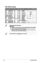
Size SS/ DS Chip Brand Chip NO. Visit the ASUS website at www.asus.com for the latest QVL. 1-20 ASUS P8P67-M PRO SS: Single-sided / DS: Double-sided DIMM support: • A*: Supports one module inserted into any slot as single-channel memory configuration. • B*: Supports one pair ...
Size SS/ DS Chip Brand Chip NO. Visit the ASUS website at www.asus.com for the latest QVL. 1-20 ASUS P8P67-M PRO SS: Single-sided / DS: Double-sided DIMM support: • A*: Supports one module inserted into any slot as single-channel memory configuration. • B*: Supports one pair ...
User Manual
Page 34
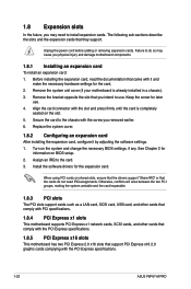
... the card to the chassis with it by adjusting the software settings. 1. Failure to use . 4. Align the card connector with the PCI Express specifications. 1-22 ASUS P8P67-M PRO Remove the system unit cover (if your motherboard is completely seated on BIOS setup. 2. See Chapter 2 for the expansion card. Install the software drivers for...
... the card to the chassis with it by adjusting the software settings. 1. Failure to use . 4. Align the card connector with the PCI Express specifications. 1-22 ASUS P8P67-M PRO Remove the system unit cover (if your motherboard is completely seated on BIOS setup. 2. See Chapter 2 for the expansion card. Install the software drivers for...
User Manual
Page 36
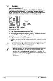
... 23 Normal (Default) Clear RTC P8P67-M PRO Clear RTC RAM To erase the RTC RAM: 1. Keep the cap on CLRTC jumper default position. Removing the cap will cause system boot failure! • ... button cell battery powers the RAM data in CMOS. Shut down the key during the boot process and enter BIOS setup to default values. 1-24 ASUS P8P67-M PRO
... 23 Normal (Default) Clear RTC P8P67-M PRO Clear RTC RAM To erase the RTC RAM: 1. Keep the cap on CLRTC jumper default position. Removing the cap will cause system boot failure! • ... button cell battery powers the RAM data in CMOS. Shut down the key during the boot process and enter BIOS setup to default values. 1-24 ASUS P8P67-M PRO
User Manual
Page 38
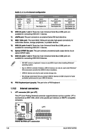
... USB 3.0 devices. 16. LPT AFD ERR# INIT# SLIN# GND GND GND GND GND GND GND GND 1-26 P8P67-M PRO P8P67-M PRO LPT connector PIN 1 STB# PD0 PD1 PD2 PD3 PD4 PD5 PD6 PD7 ACK# BUSY PE SLCT ASUS P8P67-M PRO This port connects to USB 3.0 ports for faster and better performance for connecting USB 3.0/2.0 devices. • DO...
... USB 3.0 devices. 16. LPT AFD ERR# INIT# SLIN# GND GND GND GND GND GND GND GND 1-26 P8P67-M PRO P8P67-M PRO LPT connector PIN 1 STB# PD0 PD1 PD2 PD3 PD4 PD5 PD6 PD7 ACK# BUSY PE SLCT ASUS P8P67-M PRO This port connects to USB 3.0 ports for faster and better performance for connecting USB 3.0/2.0 devices. • DO...
User Manual
Page 40
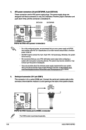
...port module cable to this connector, then install the module to connect the 4-pin / 8-pin ATX +12V power plug. COM1 PIN 1 P8P67-M PRO P8P67-M PRO Serial port (COM1) connector The COM module is for your system, refer to fit these connectors in only one orientation. com/PowerSupplyCalculator/PSCalculator.aspx... Power Supply Wattage Calculator at the back of 350 W. • DO NOT forget to a slot opening at http://support.asus. The power supply plugs are for details. 5. Serial port connector (10-1 pin COM1) This connector is purchased separately. 1-28 ASUS P8P67-M PRO
...port module cable to this connector, then install the module to connect the 4-pin / 8-pin ATX +12V power plug. COM1 PIN 1 P8P67-M PRO P8P67-M PRO Serial port (COM1) connector The COM module is for your system, refer to fit these connectors in only one orientation. com/PowerSupplyCalculator/PSCalculator.aspx... Power Supply Wattage Calculator at the back of 350 W. • DO NOT forget to a slot opening at http://support.asus. The power supply plugs are for details. 5. Serial port connector (10-1 pin COM1) This connector is purchased separately. 1-28 ASUS P8P67-M PRO
User Manual
Page 42
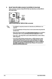
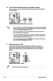
SATA6G_E1 P8P67-M PRO P8P67-M PRO Marvell® SATA 6.0 Gb/s connector • The SATA6G_E1 (navy blue) connector is not supported. • You must install Windows® XP Service Pack 3 or later ... cables. Refer to section 2.5.6 Onboard Devices Configuration for data drives only. For Windows Vista / Windows 7 OS, load only the Marvell 91xx SATA Controller Driver. 1-30 ASUS P8P67-M PRO For 32/64bit Windows XP OS, load first the Marvell shared library driver, and then load Marvell 91xx SATA Controller Driver. Marvell® Serial ATA...
SATA6G_E1 P8P67-M PRO P8P67-M PRO Marvell® SATA 6.0 Gb/s connector • The SATA6G_E1 (navy blue) connector is not supported. • You must install Windows® XP Service Pack 3 or later ... cables. Refer to section 2.5.6 Onboard Devices Configuration for data drives only. For Windows Vista / Windows 7 OS, load only the Marvell 91xx SATA Controller Driver. 1-30 ASUS P8P67-M PRO For 32/64bit Windows XP OS, load first the Marvell shared library driver, and then load Marvell 91xx SATA Controller Driver. Marvell® Serial ATA...
User Manual
Page 44
... connectors (7-pin SATA6G_1/2 [gray]) These connectors connect to [AHCI Mode] by default. P8P67-M PRO SATA6G_1 SATA6G_2 GND RSATA_TXP1 RSATA_TXN1 GND RSATA_RXP1 RSATA_RXN1 GND GND RSATA_TXP2 RSATA_TXN2 GND RSATA_RXP2 RSATA_RXN2 GND P8P67-M PRO Intel® SATA 6.0 Gb/s connectors • These connectors are using Windows® XP... Configuration for details. 11. The Serial ATA RAID feature (RAID 0, 1, 5, and 10) is purchased separately! 1-32 ASUS P8P67-M PRO TPM P8P67-M PRO PIN 1 PCICLK FRAME# PCIRST# AD3 3.3V AD0 NC 3.3VSB GND PWRDW# GND NC AD2 AD1 GND NC SERIRQ# CLKRUN# NC...
... connectors (7-pin SATA6G_1/2 [gray]) These connectors connect to [AHCI Mode] by default. P8P67-M PRO SATA6G_1 SATA6G_2 GND RSATA_TXP1 RSATA_TXN1 GND RSATA_RXP1 RSATA_RXN1 GND GND RSATA_TXP2 RSATA_TXN2 GND RSATA_RXP2 RSATA_RXN2 GND P8P67-M PRO Intel® SATA 6.0 Gb/s connectors • These connectors are using Windows® XP... Configuration for details. 11. The Serial ATA RAID feature (RAID 0, 1, 5, and 10) is purchased separately! 1-32 ASUS P8P67-M PRO TPM P8P67-M PRO PIN 1 PCICLK FRAME# PCIRST# AD3 3.3V AD0 NC 3.3VSB GND PWRDW# GND NC AD2 AD1 GND NC SERIRQ# CLKRUN# NC...
User Manual
Page 46
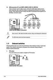
....0 connectors Never connect a 1394 cable to enable or disable the TPU function. TPU switch This switch allows you to enhance system performance. 1. TPU P8P67-M PRO P8P67-M PRO TPU switch 1-34 ASUS P8P67-M PRO USB connectors (10-1 pin USB78, USB910, USB1112, USB1314) These connectors are for overclockers and gamers who continually change settings to fine-tune performance when...
....0 connectors Never connect a 1394 cable to enable or disable the TPU function. TPU switch This switch allows you to enhance system performance. 1. TPU P8P67-M PRO P8P67-M PRO TPU switch 1-34 ASUS P8P67-M PRO USB connectors (10-1 pin USB78, USB910, USB1112, USB1314) These connectors are for overclockers and gamers who continually change settings to fine-tune performance when...
User Manual
Page 48
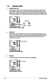
...next to the error device will continue lighting until the problem is turned to Enable. O2LED1 P8P67-M PRO P8P67-M PRO TPU LED 1-36 ASUS P8P67-M PRO SB_PWR P8P67-M PRO ON OFF Standby Power Powered Off P8P67-M PRO Onboard LED 2. This user-friendly design provides an intuitional way to indicate that you should... or plugging in sequence during motherboard booting process. The illustration below shows the location of the onboard LED. DARM LED P8P67-M PRO P8P67-M PRO DARM LED 3. TPU LED The TPU LED lights when the TPU switch is solved. Standby Power LED The motherboard comes...
...next to the error device will continue lighting until the problem is turned to Enable. O2LED1 P8P67-M PRO P8P67-M PRO TPU LED 1-36 ASUS P8P67-M PRO SB_PWR P8P67-M PRO ON OFF Standby Power Powered Off P8P67-M PRO Onboard LED 2. This user-friendly design provides an intuitional way to indicate that you should... or plugging in sequence during motherboard booting process. The illustration below shows the location of the onboard LED. DARM LED P8P67-M PRO P8P67-M PRO DARM LED 3. TPU LED The TPU LED lights when the TPU switch is solved. Standby Power LED The motherboard comes...
User Manual
Page 52
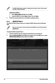
...10/18/10 10:23p 4194304 Exit DATE: 10/18/2010 P8P67-M PRO.ROM File Info MODEL: Help Info VER: DATE [Enter] Select or Load [Tab] Switch [Up/Down/PageUp/PageDown/Home/End] Move [Esc] Exit 2-2 ASUS P8P67-M PRO Always update the utility to enable it. Insert the USB ...flash disk that contains the latest BIOS file to complete the updating process. 2.1.2 ASUS EZ Flash 2 The ASUS EZ Flash 2 feature allows you start using EZ Flash 2: 1. ...
...10/18/10 10:23p 4194304 Exit DATE: 10/18/2010 P8P67-M PRO.ROM File Info MODEL: Help Info VER: DATE [Enter] Select or Load [Tab] Switch [Up/Down/PageUp/PageDown/Home/End] Move [Esc] Exit 2-2 ASUS P8P67-M PRO Always update the utility to enable it. Insert the USB ...flash disk that contains the latest BIOS file to complete the updating process. 2.1.2 ASUS EZ Flash 2 The ASUS EZ Flash 2 feature allows you start using EZ Flash 2: 1. ...
User Manual
Page 54
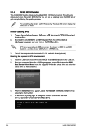
...same as shown. Download the latest BIOS file and BIOS Updater from Drive C (optical drive) to switch the disk from the ASUS website at http://support.asus.com and save the BIOS file and BIOS Updater to update BIOS in DOS environment 1. Before updating BIOS 1. Turn off the computer... and disconnect all SATA hard disk drives (optional). Booting the system in DOS environment. Boot your computer. When the ASUS Logo appears, press to FreeDOS (http://www.freedos.org)! Welcome to show the BIOS Boot Device Select Menu. C:\>d: D:\> 2-4 ASUS P8P67-M PRO
...same as shown. Download the latest BIOS file and BIOS Updater from Drive C (optical drive) to switch the disk from the ASUS website at http://support.asus.com and save the BIOS file and BIOS Updater to update BIOS in DOS environment 1. Before updating BIOS 1. Turn off the computer... and disconnect all SATA hard disk drives (optional). Booting the system in DOS environment. Boot your computer. When the ASUS Logo appears, press to FreeDOS (http://www.freedos.org)! Welcome to show the BIOS Boot Device Select Menu. C:\>d: D:\> 2-4 ASUS P8P67-M PRO
User Manual
Page 56
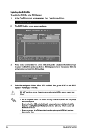
... after updating the BIOS file if you sure to update BIOS? Are you have disconnected them. 2-6 ASUS P8P67-M PRO Yes No 4. Select Yes and press . Refer to section 2.9 Exit menu for DOS V1.18 Current ROM BOARD: P8P67-M PRO VER: 0202 DATE: 10/18/2010 Update ROM BOARD: Unknown VER: Unknown DATE: Unknown PATH: A:\ A: P8P67MP...
... after updating the BIOS file if you sure to update BIOS? Are you have disconnected them. 2-6 ASUS P8P67-M PRO Yes No 4. Select Yes and press . Refer to section 2.9 Exit menu for DOS V1.18 Current ROM BOARD: P8P67-M PRO VER: 0202 DATE: 10/18/2010 Update ROM BOARD: Unknown VER: Unknown DATE: Unknown PATH: A:\ A: P8P67MP...
User Manual
Page 58
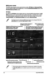
... to the system. • The Boot Menu(F8) button is available only when the boot device is installed to the system. 2-8 ASUS P8P67-M PRO Selects the display language of the BIOS setup program Clicks to select the display language, system performance mode and boot device priority. You can...of the selected mode on the right hand side Normal mode ASUS Optimal mode Selects the boot device priority • The boot device options vary depending on the devices you enter the BIOS setup program. EZ Mode Friday [10/08/2010] P8P67-M PRO BIOS Version : 0202 CPU Type : Genuine Intel(R) CPU...
... to the system. • The Boot Menu(F8) button is available only when the boot device is installed to the system. 2-8 ASUS P8P67-M PRO Selects the display language of the BIOS setup program Clicks to select the display language, system performance mode and boot device priority. You can...of the selected mode on the right hand side Normal mode ASUS Optimal mode Selects the boot device priority • The boot device options vary depending on the devices you enter the BIOS setup program. EZ Mode Friday [10/08/2010] P8P67-M PRO BIOS Version : 0202 CPU Type : Genuine Intel(R) CPU...


