User Manual
Page 3
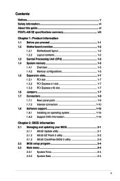
... 1-2 1.2.1 Motherboard layout 1-2 1.2.2 Layout contents 1-2 1.3 Central Processing Unit (CPU 1-3 1.4 System memory 1-3 1.4.1 Overview 1-3 1.4.2 Memory configurations 1-3 1.5 Expansion slots 1-7 1.5.1 PCI slot 1-7 1.5.2 PCI Express x1 slot 1-7 1.5.3 PCI Express x16 slot 1-7 1.6 Jumpers 1-7 1.7 Connectors 1-9 1.7.1 Rear panel ports 1-9 1.7.2 Internal connectors 1-10 1.8 Software support 1-15 1.8.1 Installing an operating system 1-15 1.8.2 Support DVD information 1-15 Chapter 2: BIOS information 2.1 Managing and updating your BIOS 2-1 2.1.1 ASUS...
... 1-2 1.2.1 Motherboard layout 1-2 1.2.2 Layout contents 1-2 1.3 Central Processing Unit (CPU 1-3 1.4 System memory 1-3 1.4.1 Overview 1-3 1.4.2 Memory configurations 1-3 1.5 Expansion slots 1-7 1.5.1 PCI slot 1-7 1.5.2 PCI Express x1 slot 1-7 1.5.3 PCI Express x16 slot 1-7 1.6 Jumpers 1-7 1.7 Connectors 1-9 1.7.1 Rear panel ports 1-9 1.7.2 Internal connectors 1-10 1.8 Software support 1-15 1.8.1 Installing an operating system 1-15 1.8.2 Support DVD information 1-15 Chapter 2: BIOS information 2.1 Managing and updating your BIOS 2-1 2.1.1 ASUS...
User Manual
Page 8
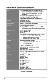
.... 8 x USB2.0 ports (4 ports at mid-board, 4 ports at back panel ASUS CrashFree BIOS 3 ASUS Q-Fan ASUS EZ Flash 2 ASUS MyLogo 2 1 x PS/2 keyboard port 1 x PS/2 mouse port 1 x VGA port 1 x COM 1 x LAN (RJ-45) port 4 x USB 2.0 ports 6-channel audio I/O port (continued on the next page) viii P5KPL-AM SE specifications summary CPU Chipset Front Side Bus Memory Expansion Slots...
.... 8 x USB2.0 ports (4 ports at mid-board, 4 ports at back panel ASUS CrashFree BIOS 3 ASUS Q-Fan ASUS EZ Flash 2 ASUS MyLogo 2 1 x PS/2 keyboard port 1 x PS/2 mouse port 1 x VGA port 1 x COM 1 x LAN (RJ-45) port 4 x USB 2.0 ports 6-channel audio I/O port (continued on the next page) viii P5KPL-AM SE specifications summary CPU Chipset Front Side Bus Memory Expansion Slots...
User Manual
Page 9
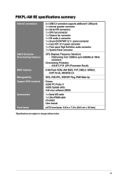
... uATX form factor: 9.6 in x 7.2 in connector 1 x 24-pin EATXPWR 12 V power connector 1 x 4-pin ATX 12 V power connector 1 x Front panel High Definition audio connector 1 x System Panel connector SFS (Stepless Frequency Selection) - P5KPL-AM SE specifications summary Internal connectors ASUS Exclusive Overclocking Features BIOS features Manageability Support DVD contents Accessories Form factor 2 x USB 2.0 connectors supports additional 4 USB...
... uATX form factor: 9.6 in x 7.2 in connector 1 x 24-pin EATXPWR 12 V power connector 1 x 4-pin ATX 12 V power connector 1 x Front panel High Definition audio connector 1 x System Panel connector SFS (Stepless Frequency Selection) - P5KPL-AM SE specifications summary Internal connectors ASUS Exclusive Overclocking Features BIOS features Manageability Support DVD contents Accessories Form factor 2 x USB 2.0 connectors supports additional 4 USB...
User Manual
Page 11
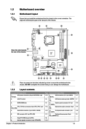
The edge with external ports goes to the chassis. System panel connector (10-1 pin F_PANEL) 1-12 12. ATX power connectors (24-pin EATXPWR, 4-pin ATX12V) 2. Keyboard/mouse power (3-pin PS2_USBPW1-4) 1-8 1-13 Page 1-11 1-7 1-14 1-14 1-12 1-9 Chapter 1: ...I/O Lithium Cell CMOS Power PCIEX1_1 P5KPL-AM SE SPEAKER Intel® ICH7 ALC662 AAFP F_PANEL CD PCI1 SB_PWR USBPW5-8 USB78 CLRTC USB56 PRI_IDE 8Mb BIOS SATA2 SATA1 Place six screws into the chassis in the correct orientation. Doing so can damage the motherboard. 1.2.2 Layout contents Connectors/Jumpers/...
The edge with external ports goes to the chassis. System panel connector (10-1 pin F_PANEL) 1-12 12. ATX power connectors (24-pin EATXPWR, 4-pin ATX12V) 2. Keyboard/mouse power (3-pin PS2_USBPW1-4) 1-8 1-13 Page 1-11 1-7 1-14 1-14 1-12 1-9 Chapter 1: ...I/O Lithium Cell CMOS Power PCIEX1_1 P5KPL-AM SE SPEAKER Intel® ICH7 ALC662 AAFP F_PANEL CD PCI1 SB_PWR USBPW5-8 USB78 CLRTC USB56 PRI_IDE 8Mb BIOS SATA2 SATA1 Place six screws into the chassis in the correct orientation. Doing so can damage the motherboard. 1.2.2 Layout contents Connectors/Jumpers/...

User Manual
Page 17
...Plug the power cord and turn off is required before rebooting the system. Shut down the key during the boot process and enter BIOS setup to the chipset limitation, AC power off and on the power supply or unplug and plug the power cord before you to ...•words. For system failure due to overclocking. Move the jumper cap from pins 1-2 (default) to pins 1-2. 4. CLRTC 12 23 P5KPL-AM SE Normal (Default) Clear RTC P5KPL-AM SE Clear RTC RAM Chapter 1: Product introduction 1-8 Turn OFF the computer and unplug the power cord. 2. enter data. 2. Clear RTC RAM ...
...Plug the power cord and turn off is required before rebooting the system. Shut down the key during the boot process and enter BIOS setup to the chipset limitation, AC power off and on the power supply or unplug and plug the power cord before you to ...•words. For system failure due to overclocking. Move the jumper cap from pins 1-2 (default) to pins 1-2. 4. CLRTC 12 23 P5KPL-AM SE Normal (Default) Clear RTC P5KPL-AM SE Clear RTC RAM Chapter 1: Product introduction 1-8 Turn OFF the computer and unplug the power cord. 2. enter data. 2. Clear RTC RAM ...
User Manual
Page 18
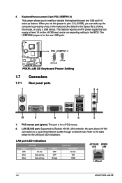
...This feature requires an ATX power supply that can wake up feature. The USBPW56 jumper is for the LAN port LED indications. Supported by pressing a key on the +5VSB lead, and a corresponding setting in the BIOS. Refer to a Local... Area Network (LAN) through a network hub. This port is the Space Bar), clicking the mouse, or using a USB device. PS2_USBPW1-4 12 23 P5KPL-AM SE +5V +5VSB (Default) P5KPL-AM SE Keyboard Power Setting 1.7 1.7.1 1 Connectors .../LINK SPEED LED LED LAN port 1-9 ASUS P5KPL-AM SE
...This feature requires an ATX power supply that can wake up feature. The USBPW56 jumper is for the LAN port LED indications. Supported by pressing a key on the +5VSB lead, and a corresponding setting in the BIOS. Refer to a Local... Area Network (LAN) through a network hub. This port is the Space Bar), clicking the mouse, or using a USB device. PS2_USBPW1-4 12 23 P5KPL-AM SE +5V +5VSB (Default) P5KPL-AM SE Keyboard Power Setting 1.7 1.7.1 1 Connectors .../LINK SPEED LED LED LAN port 1-9 ASUS P5KPL-AM SE
User Manual
Page 21
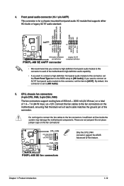
...-definition front panel audio module to this connector, set the Front Panel Type item in the BIOS setup to [HD Audio]; Chapter 1: Product introduction 1-12 These are not jumpers! Front panel... motherboard, ensuring that the black wire of each cable matches the ground pin of 1 A ~ 7 A (84 W max.) at +12V. 4. By default, this connector, set to the fan connectors. P5KPL-AM SE ...CPU_FAN CPU FAN PWM CPU FAN IN CPU FAN PWR GND CHA_FAN Rotation +12V GND P5KPL-AM SE fan connectors Only the CPU_FAN connector support the ASUS Advanced Q-Fan feature....
...-definition front panel audio module to this connector, set the Front Panel Type item in the BIOS setup to [HD Audio]; Chapter 1: Product introduction 1-12 These are not jumpers! Front panel... motherboard, ensuring that the black wire of each cable matches the ground pin of 1 A ~ 7 A (84 W max.) at +12V. 4. By default, this connector, set to the fan connectors. P5KPL-AM SE ...CPU_FAN CPU FAN PWM CPU FAN IN CPU FAN PWR GND CHA_FAN Rotation +12V GND P5KPL-AM SE fan connectors Only the CPU_FAN connector support the ASUS Advanced Q-Fan feature....
User Manual
Page 23
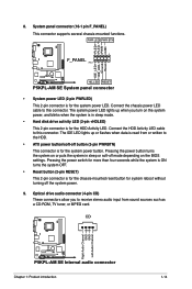
...MPEG card. CD Right Audio Channel GND GND Left Audio Channel P5KPL-AM SE P5KPL-AM SE Internal audio connector Chapter 1: Product introduction 1-14 Ground Reset 8. Connect the chassis power LED cable to the HDD. • ATX power button/soft-off button (2-pin PWRBTN) This connector is...P5KPL-AM SE HD_LED RESET P5KPL-AM SE System panel connector • System power LED (2-pin PWRLED) This 2-pin connector is for the system power LED. The IDE LED lights up when you to receive stereo audio input from or written to this connector. Pressing the power button turns the system on the BIOS...
...MPEG card. CD Right Audio Channel GND GND Left Audio Channel P5KPL-AM SE P5KPL-AM SE Internal audio connector Chapter 1: Product introduction 1-14 Ground Reset 8. Connect the chassis power LED cable to the HDD. • ATX power button/soft-off button (2-pin PWRBTN) This connector is...P5KPL-AM SE HD_LED RESET P5KPL-AM SE System panel connector • System power LED (2-pin PWRLED) This 2-pin connector is for the system power LED. The IDE LED lights up when you to receive stereo audio input from or written to this connector. Pressing the power button turns the system on the BIOS...
User Manual
Page 26
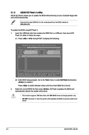
...system while updating the BIOS to enable it. Download the latest BIOS file for this motherboard from the ASUS website at www.asus.com. Go to the Tools menu to select EZ Flash 2 and press to prevent system boot failure! 2-2 ASUS P5KPL-AM SE 2.1.2 ASUS EZ Flash 2 utility ASUS EZ Flash 2 ...allows you to update the BIOS without having to...
...system while updating the BIOS to enable it. Download the latest BIOS file for this motherboard from the ASUS website at www.asus.com. Go to the Tools menu to select EZ Flash 2 and press to prevent system boot failure! 2-2 ASUS P5KPL-AM SE 2.1.2 ASUS EZ Flash 2 utility ASUS EZ Flash 2 ...allows you to update the BIOS without having to...
User Manual
Page 28
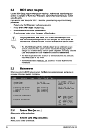
...] Allows you to set the system date. 2-4 ASUS P5KPL-AM SE Select the Load Setup Defaults item under the Exit menu. 2.2 BIOS setup program Use the BIOS Setup program when you are for reference only. See section 2.8 Exit menu. • The BIOS setup screens in this section are installing a motherboard, reconfiguring your data or system. This section...
...] Allows you to set the system date. 2-4 ASUS P5KPL-AM SE Select the Load Setup Defaults item under the Exit menu. 2.2 BIOS setup program Use the BIOS Setup program when you are for reference only. See section 2.8 Exit menu. • The BIOS setup screens in this section are installing a motherboard, reconfiguring your data or system. This section...
User Manual
Page 30
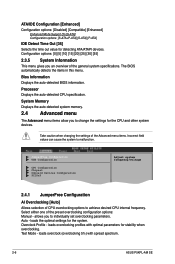
... the auto-detected BIOS information. Take caution when changing the settings of CPU overclocking options to malfunction. Auto - loads overclocking profiles with spread spectrum. 2-6 ASUS P5KPL-AM SE Select either one of the general system specifications. Processor Displays the... [20] [25] [30] [35] 2.3.5 System Information This menu gives you to change the settings for stability when overclocking. The BIOS automatically detects the items in this menu. loads overclock (overclocking 5%) with optimal parameters for the CPU and other system devices. ATA/IDE ...
... the auto-detected BIOS information. Take caution when changing the settings of CPU overclocking options to malfunction. Auto - loads overclocking profiles with spread spectrum. 2-6 ASUS P5KPL-AM SE Select either one of the general system specifications. Processor Displays the... [20] [25] [30] [35] 2.3.5 System Information This menu gives you to change the settings for stability when overclocking. The BIOS automatically detects the items in this menu. loads overclock (overclocking 5%) with optimal parameters for the CPU and other system devices. ATA/IDE ...
User Manual
Page 32
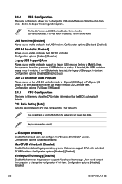
... USB functions.Configuration options: [Disabled] [Enabled] USB 2.0 Controller [Enabled] Allows you to boot legacy operating systems that the BIOS automatically detects. If detected, the USB controller legacy mode is set in CMOS, then the actual and set the USB 2.0 controller...configuration options. Select an item then press to enable or disable support for legacy USB devices. Configuration options: [Disabled] [Enabled] 2-8 ASUS P5KPL-AM SE Key in this menu show the auto-detected values. Configuration options: [FullSpeed ] [HiSpeed ] 2.4.3 CPU Configuration The items in ratio ...
... USB functions.Configuration options: [Disabled] [Enabled] USB 2.0 Controller [Enabled] Allows you to boot legacy operating systems that the BIOS automatically detects. If detected, the USB controller legacy mode is set in CMOS, then the actual and set the USB 2.0 controller...configuration options. Select an item then press to enable or disable support for legacy USB devices. Configuration options: [Disabled] [Enabled] 2-8 ASUS P5KPL-AM SE Key in this menu show the auto-detected values. Configuration options: [FullSpeed ] [HiSpeed ] 2.4.3 CPU Configuration The items in ratio ...
User Manual
Page 34
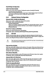
... not required for boot. Configuration options: [Disabled] [Enabled] 2-10 ASUS P5KPL-AM SE Configuration options: [Enabled] [Disabled] LAN Option ROM [Disabled] Allows you to select the Serial Port1 base address. When set to [No], BIOS configures all the devices in the onboard LAN controller. Configuration options: [... PCI VGA [Yes] When set the audio controller. South Bridge Configuration Audio Controller [Azalia] Allows you to set to [Yes], BIOS assigns an IRQ to PCI VGA card if the card requests for an IRQ. The menu includes setting IRQ and DMA channel resources for...
... not required for boot. Configuration options: [Disabled] [Enabled] 2-10 ASUS P5KPL-AM SE Configuration options: [Enabled] [Disabled] LAN Option ROM [Disabled] Allows you to select the Serial Port1 base address. When set to [No], BIOS configures all the devices in the onboard LAN controller. Configuration options: [... PCI VGA [Yes] When set the audio controller. South Bridge Configuration Audio Controller [Azalia] Allows you to set to [Yes], BIOS assigns an IRQ to PCI VGA card if the card requests for an IRQ. The menu includes setting IRQ and DMA channel resources for...
User Manual
Page 38
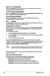
... not allow you successfully set your BIOS password, you to any field. [Limited] - Select the Change Supervisor Password item and press . 2. See section 1.9 Jumpers for the F1 key to set or change the supervisor password, follow the same steps in the Setup utility. 2-14 ASUS P5KPL-AM SE To change the supervisor password. To...
... not allow you successfully set your BIOS password, you to any field. [Limited] - Select the Change Supervisor Password item and press . 2. See section 1.9 Jumpers for the F1 key to set or change the supervisor password, follow the same steps in the Setup utility. 2-14 ASUS P5KPL-AM SE To change the supervisor password. To...
User Manual
Page 40
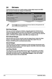
...-screen F1 General Help F10 Save and Exit Exit & Save Changes ESC Exit Once you are finished making your changes to the BIOS items. Main Advanced BIOS SETUP UTILITY Power Boot Tools Exit Exit Options Exit & Save Changes Exit & Discard Changes Discard Changes Load Setup Defaults Exit system ...Setup Defaults This option allows you to load the default values for a confirmation before saving the values to the non-volatile RAM. 2-16 ASUS P5KPL-AM SE 2.8 Exit menu The Exit menu items allow you to load the optimal or failsafe default values for this operation. Select one of the ...
...-screen F1 General Help F10 Save and Exit Exit & Save Changes ESC Exit Once you are finished making your changes to the BIOS items. Main Advanced BIOS SETUP UTILITY Power Boot Tools Exit Exit Options Exit & Save Changes Exit & Discard Changes Discard Changes Load Setup Defaults Exit system ...Setup Defaults This option allows you to load the default values for a confirmation before saving the values to the non-volatile RAM. 2-16 ASUS P5KPL-AM SE 2.8 Exit menu The Exit menu items allow you to load the optimal or failsafe default values for this operation. Select one of the ...


