User Manual
Page 8
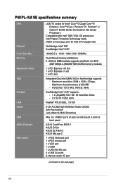
... next page) viii Maximum resolution: 2048 x 1536 x 32 bpp, - Maximum shared memory of 256 MB - P5KPL-AM SE specifications summary CPU Chipset Front Side Bus Memory Expansion Slots VGA Storage LAN Audio USB ASUS Features Rear panel LGA775 socket for Intel® Core™2 Quad/ Core™2 Extreme / Core™2 Duo / Pentium® D / Pentium...
... next page) viii Maximum resolution: 2048 x 1536 x 32 bpp, - Maximum shared memory of 256 MB - P5KPL-AM SE specifications summary CPU Chipset Front Side Bus Memory Expansion Slots VGA Storage LAN Audio USB ASUS Features Rear panel LGA775 socket for Intel® Core™2 Quad/ Core™2 Extreme / Core™2 Duo / Pentium® D / Pentium...
User Manual
Page 10
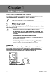
... page ix for buying an ASUS® P5KPL-AM SE motherboard! Chapter 1 Product introduction Thank you start installing the motherboard, and hardware devices on a grounded antistatic pad or in the bag that came with a standby power LED that lights up to indicate that the ATX power supply is detached from the wall socket before touching any component...
... page ix for buying an ASUS® P5KPL-AM SE motherboard! Chapter 1 Product introduction Thank you start installing the motherboard, and hardware devices on a grounded antistatic pad or in the bag that came with a standby power LED that lights up to indicate that the ATX power supply is detached from the wall socket before touching any component...
User Manual
Page 11
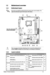
... Doing so can damage the motherboard. 1.2.2 Layout contents Connectors/Jumpers/Slots 1. ATX power connectors (24-pin EATXPWR, 4-pin ATX12V) 2. Serial ATA connectors (7-pin SATA1, SATA2) 6. Clear RTC RAM (3-pin CLRTC) 8. System panel connector (10-1 pin F_PANEL) 1-12 12. LGA775 socket 3. USB connectors (10-1...LAN1_USB12 AUDIO RTL 8102EL CHA_FAN Intel® G31 PCIEX16 RTM870T-954 Super I/O Lithium Cell CMOS Power PCIEX1_1 P5KPL-AM SE SPEAKER Intel® ICH7 ALC662 AAFP F_PANEL CD PCI1 SB_PWR USBPW5-8 USB78 CLRTC USB56 PRI_IDE 8Mb BIOS SATA2...
... Doing so can damage the motherboard. 1.2.2 Layout contents Connectors/Jumpers/Slots 1. ATX power connectors (24-pin EATXPWR, 4-pin ATX12V) 2. Serial ATA connectors (7-pin SATA1, SATA2) 6. Clear RTC RAM (3-pin CLRTC) 8. System panel connector (10-1 pin F_PANEL) 1-12 12. LGA775 socket 3. USB connectors (10-1...LAN1_USB12 AUDIO RTL 8102EL CHA_FAN Intel® G31 PCIEX16 RTM870T-954 Super I/O Lithium Cell CMOS Power PCIEX1_1 P5KPL-AM SE SPEAKER Intel® ICH7 ALC662 AAFP F_PANEL CD PCI1 SB_PWR USBPW5-8 USB78 CLRTC USB56 PRI_IDE 8Mb BIOS SATA2...
User Manual
Page 12
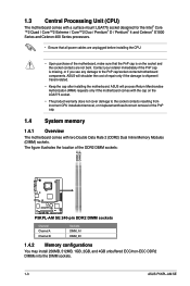
...; Keep the cap after installing the motherboard. The figure illustrates the location of repair only if the damage is on the socket and the socket contacts are not bent. ASUS will shoulder the cost of the DDR2 DIMM sockets: DIMM_A1 DIMM_B1 P5KPL-AM SE P5KPL-AM SE 240-pin DDR2 DIMM sockets Channel Channel A Channel B Sockets DIMM_A1 DIMM_B1 1.4.2 Memory configurations You...
...; Keep the cap after installing the motherboard. The figure illustrates the location of repair only if the damage is on the socket and the socket contacts are not bent. ASUS will shoulder the cost of the DDR2 DIMM sockets: DIMM_A1 DIMM_B1 P5KPL-AM SE P5KPL-AM SE 240-pin DDR2 DIMM sockets Channel Channel A Channel B Sockets DIMM_A1 DIMM_B1 1.4.2 Memory configurations You...


