
User Manual
Page 31
Version 1.19(ASUS V2.07(03.11.24BB)) Copyright (C) 2002 American Megatrends, Inc. ok A:\> 當 BIOS DOS 31 Reading flash ..... BIOS 2.1 使用 AFUDOS BIOS AFUDOS DOS BIOS BIOS 程式。AFUDOS BIOS BIOS BIOS 程式 BIOS 程式。 1.2MB BIOS 1 AFUDOS 程式(afudos. done Write to file...... exe 2 DOS afudos /o[filename filename A:\>afudos /oOLDBIOS1.rom 3. 按下 afudos /oOLDBIOS1.rom AMI Firmware Update Utility - All rights reserved.
Version 1.19(ASUS V2.07(03.11.24BB)) Copyright (C) 2002 American Megatrends, Inc. ok A:\> 當 BIOS DOS 31 Reading flash ..... BIOS 2.1 使用 AFUDOS BIOS AFUDOS DOS BIOS BIOS 程式。AFUDOS BIOS BIOS BIOS 程式 BIOS 程式。 1.2MB BIOS 1 AFUDOS 程式(afudos. done Write to file...... exe 2 DOS afudos /o[filename filename A:\>afudos /oOLDBIOS1.rom 3. 按下 afudos /oOLDBIOS1.rom AMI Firmware Update Utility - All rights reserved.

User Manual
Page 32
... Firmware Update Utility - All rights reserved. Erasing flash ...... done Writing flash ...... done Advance Check ...... Erasing flash ...... Do not turn off power during flash BIOS Reading file ....... Version 1.19(ASUS V2.07(03.11.24BB)) Copyright (C) 2002 American Megatrends, Inc. WARNING!! All rights reserved. done Reading flash ...... done Verifying flash .... WARNING!! done Advance...
... Firmware Update Utility - All rights reserved. Erasing flash ...... done Writing flash ...... done Advance Check ...... Erasing flash ...... Do not turn off power during flash BIOS Reading file ....... Version 1.19(ASUS V2.07(03.11.24BB)) Copyright (C) 2002 American Megatrends, Inc. WARNING!! All rights reserved. done Reading flash ...... done Verifying flash .... WARNING!! done Advance...

User Manual
Page 33
... Message: Do You Want To Save Bios (Y/N) 33 2.2 使用 AwardBIOS Flash BIOS AwardBIOS Flash AwardBIOS Flash 程式(AWDFLASH.EXE BIOS AwardBIOS Flash BIOS 程式。 1 http://tw.asus.com BIOS M2N-VM HDMI.bin FAT 32/16 格式的 USB BIOS 2 CD/DVD AwardBIOS Flash BIOS 3 DOS 4. 當 A BIOS 檔案與 AwardBIOS Flash...
... Message: Do You Want To Save Bios (Y/N) 33 2.2 使用 AwardBIOS Flash BIOS AwardBIOS Flash AwardBIOS Flash 程式(AWDFLASH.EXE BIOS AwardBIOS Flash BIOS 程式。 1 http://tw.asus.com BIOS M2N-VM HDMI.bin FAT 32/16 格式的 USB BIOS 2 CD/DVD AwardBIOS Flash BIOS 3 DOS 4. 當 A BIOS 檔案與 AwardBIOS Flash...

User Manual
Page 34
....14 (C) Phoenix Technologies Ltd. PMC Pm49FL004T LPC/FWH File Name to Continue Write OK F1 Reset No Update Write Fail 34 BIOS 7 BIOS N BIOS 8 BIOS BIOS AwardBIOS Flash Utility for ASUS V1.14 (C) Phoenix Technologies Ltd. All Rights Reserved For C51PV-MCP51-M2A-VM HDMI-00 DATE:04/13/2006 Flash Type - All Rights Reserved For...
....14 (C) Phoenix Technologies Ltd. PMC Pm49FL004T LPC/FWH File Name to Continue Write OK F1 Reset No Update Write Fail 34 BIOS 7 BIOS N BIOS 8 BIOS BIOS AwardBIOS Flash Utility for ASUS V1.14 (C) Phoenix Technologies Ltd. All Rights Reserved For C51PV-MCP51-M2A-VM HDMI-00 DATE:04/13/2006 Flash Type - All Rights Reserved For...
User Manual
Page 3
... 1-2 1.2.1 Motherboard layout 1-2 1.2.2 Layout contents 1-2 1.3 Central Processing Unit (CPU 1-3 1.4 System memory 1-3 1.4.1 Overview 1-3 1.4.2 Memory configurations 1-3 1.5 Expansion slots 1-7 1.5.1 PCI slot 1-7 1.5.2 PCI Express x1 slot 1-7 1.5.3 PCI Express x16 slot 1-7 1.6 Jumpers 1-7 1.7 Connectors 1-9 1.7.1 Rear panel ports 1-9 1.7.2 Internal connectors 1-10 1.8 Software support 1-15 1.8.1 Installing an operating system 1-15 1.8.2 Support DVD information 1-15 Chapter 2: BIOS information 2.1 Managing and updating your BIOS 2-1 2.1.1 ASUS...
... 1-2 1.2.1 Motherboard layout 1-2 1.2.2 Layout contents 1-2 1.3 Central Processing Unit (CPU 1-3 1.4 System memory 1-3 1.4.1 Overview 1-3 1.4.2 Memory configurations 1-3 1.5 Expansion slots 1-7 1.5.1 PCI slot 1-7 1.5.2 PCI Express x1 slot 1-7 1.5.3 PCI Express x16 slot 1-7 1.6 Jumpers 1-7 1.7 Connectors 1-9 1.7.1 Rear panel ports 1-9 1.7.2 Internal connectors 1-10 1.8 Software support 1-15 1.8.1 Installing an operating system 1-15 1.8.2 Support DVD information 1-15 Chapter 2: BIOS information 2.1 Managing and updating your BIOS 2-1 2.1.1 ASUS...
User Manual
Page 6
...product, ensure that all cables are correctly connected and the power cables are not damaged. Operation safety • Before installing the motherboard and adding devices on a flat and stable surface. • If you add a device. • Before connecting or removing signal cables from... This guide contains the following parts: • Chapter 1: Product introduction This chapter describes the features of the motherboard and the new technology it supports. • Chapter 2: BIOS setup This chapter tells how to fix it , carefully read all the manuals that all power cables from connectors...
...product, ensure that all cables are correctly connected and the power cables are not damaged. Operation safety • Before installing the motherboard and adding devices on a flat and stable surface. • If you add a device. • Before connecting or removing signal cables from... This guide contains the following parts: • Chapter 1: Product introduction This chapter describes the features of the motherboard and the new technology it supports. • Chapter 2: BIOS setup This chapter tells how to fix it , carefully read all the manuals that all power cables from connectors...
User Manual
Page 8
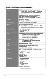
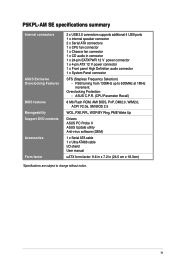
.... 8 x USB2.0 ports (4 ports at mid-board, 4 ports at back panel ASUS CrashFree BIOS 3 ASUS Q-Fan ASUS EZ Flash 2 ASUS MyLogo 2 1 x PS/2 keyboard port 1 x PS/2 mouse port 1 x VGA port 1 x COM 1 x LAN (RJ-45) port 4 x USB 2.0 ports 6-channel audio I/O port (continued on the next page) viii P5KPL-AM SE specifications summary CPU Chipset Front Side Bus Memory Expansion Slots...
.... 8 x USB2.0 ports (4 ports at mid-board, 4 ports at back panel ASUS CrashFree BIOS 3 ASUS Q-Fan ASUS EZ Flash 2 ASUS MyLogo 2 1 x PS/2 keyboard port 1 x PS/2 mouse port 1 x VGA port 1 x COM 1 x LAN (RJ-45) port 4 x USB 2.0 ports 6-channel audio I/O port (continued on the next page) viii P5KPL-AM SE specifications summary CPU Chipset Front Side Bus Memory Expansion Slots...
User Manual
Page 9
P5KPL-AM SE specifications summary Internal connectors ASUS Exclusive Overclocking Features BIOS features Manageability Support DVD contents Accessories Form factor 2 x USB 2.0 connectors supports additional 4 USB ports 1 x internal speaker connector 2 x Serial ATA connectors 1 x CPU...V2.0a, SM BIOS 2.5 WOL, PXE,RPL, WOR BY Ring, PME Wake Up Drivers ASUS PC Probe II ASUS Update utility Anti-virus software (OEM) 1 x Serial ATA cable 1 x Ultra ATA66 cable I/O shield User manual uATX form factor: 9.6 in x 7.2 in connector 1 x 24-pin EATXPWR 12 V power connector 1 x 4-pin ATX 12 V power ...
P5KPL-AM SE specifications summary Internal connectors ASUS Exclusive Overclocking Features BIOS features Manageability Support DVD contents Accessories Form factor 2 x USB 2.0 connectors supports additional 4 USB ports 1 x internal speaker connector 2 x Serial ATA connectors 1 x CPU...V2.0a, SM BIOS 2.5 WOL, PXE,RPL, WOR BY Ring, PME Wake Up Drivers ASUS PC Probe II ASUS Update utility Anti-virus software (OEM) 1 x Serial ATA cable 1 x Ultra ATA66 cable I/O shield User manual uATX form factor: 9.6 in x 7.2 in connector 1 x 24-pin EATXPWR 12 V power connector 1 x 4-pin ATX 12 V power ...
User Manual
Page 11
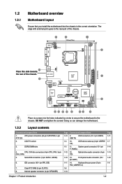
... G31 PCIEX16 RTM870T-954 Super I/O Lithium Cell CMOS Power PCIEX1_1 P5KPL-AM SE SPEAKER Intel® ICH7 ALC662 AAFP F_PANEL CD PCI1 SB_PWR USBPW5-8 USB78 CLRTC USB56 PRI_IDE 8Mb BIOS SATA2 SATA1 Place six screws into the chassis in the correct orientation...overtighten the screws! ATX power connectors (24-pin EATXPWR, 4-pin ATX12V) 2. Clear RTC RAM (3-pin CLRTC) 8. IDE connector (40-1 pin PRI_IDE) 7. System panel connector (10-1 pin F_PANEL) 1-12 12. 1.2 1.2.1 Motherboard overview Motherboard layout Ensure that you install the motherboard into the holes ...
... G31 PCIEX16 RTM870T-954 Super I/O Lithium Cell CMOS Power PCIEX1_1 P5KPL-AM SE SPEAKER Intel® ICH7 ALC662 AAFP F_PANEL CD PCI1 SB_PWR USBPW5-8 USB78 CLRTC USB56 PRI_IDE 8Mb BIOS SATA2 SATA1 Place six screws into the chassis in the correct orientation...overtighten the screws! ATX power connectors (24-pin EATXPWR, 4-pin ATX12V) 2. Clear RTC RAM (3-pin CLRTC) 8. IDE connector (40-1 pin PRI_IDE) 7. System panel connector (10-1 pin F_PANEL) 1-12 12. 1.2 1.2.1 Motherboard overview Motherboard layout Ensure that you install the motherboard into the holes ...

User Manual
Page 17
...which include system setup information such as system •words. You must turn ON the computer. 6. enter data. CLRTC 12 23 P5KPL-AM SE Normal (Default) Clear RTC P5KPL-AM SE Clear RTC RAM Chapter 1: Product introduction 1-8 To erase the RTC RAM: 1. Turn OFF the computer and unplug the power cord. ... the CMOS RTC RAM data. Move the jumper cap from pins 1-2 (default) to re- Hold down and reboot the system, then the BIOS automatically resets the parameter settings to default values. • Due to overclocking, use the C.P.R. Plug the power cord and turn off is required...
...which include system setup information such as system •words. You must turn ON the computer. 6. enter data. CLRTC 12 23 P5KPL-AM SE Normal (Default) Clear RTC P5KPL-AM SE Clear RTC RAM Chapter 1: Product introduction 1-8 To erase the RTC RAM: 1. Turn OFF the computer and unplug the power cord. ... the CMOS RTC RAM data. Move the jumper cap from pins 1-2 (default) to re- Hold down and reboot the system, then the BIOS automatically resets the parameter settings to default values. • Due to overclocking, use the C.P.R. Plug the power cord and turn off is required...
User Manual
Page 18
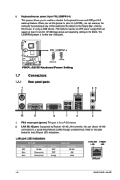
...requires an ATX power supply that can wake up feature. LAN port LED indications Status OFF Blink Blink ACT LED Description No link Data activity Data activity Status OFF OFF Orange Speed LED Description No link 10M 100M ACT/LINK SPEED LED LED LAN port 1-9 ASUS P5KPL-AM SE The ...jumper to a Local Area Network (LAN) through a network hub. Supported by pressing a key on the +5VSB lead, and a corresponding setting in the BIOS. Keyboard/mouse power (3-pin PS2_USBPW1-4) This jumper allows you set this port allows 10/100 connection to pins 2-3 (+5VSB), you can supply at least 1A...
...requires an ATX power supply that can wake up feature. LAN port LED indications Status OFF Blink Blink ACT LED Description No link Data activity Data activity Status OFF OFF Orange Speed LED Description No link 10M 100M ACT/LINK SPEED LED LED LAN port 1-9 ASUS P5KPL-AM SE The ...jumper to a Local Area Network (LAN) through a network hub. Supported by pressing a key on the +5VSB lead, and a corresponding setting in the BIOS. Keyboard/mouse power (3-pin PS2_USBPW1-4) This jumper allows you set this port allows 10/100 connection to pins 2-3 (+5VSB), you can supply at least 1A...
User Manual
Page 21
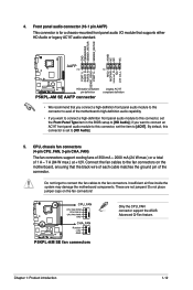
...panel audio module to this connector to avail of the motherboard's high-definition audio capability. • If you want to connect a high-definition front panel audio module to this connector, set the Front Panel Type item in the BIOS setup to [HD Audio]. 5. By default, this ...audio standard. These are not jumpers! Insufficient air flow inside the system may damage the motherboard components. P5KPL-AM SE CPU_FAN CPU FAN PWM CPU FAN IN CPU FAN PWR GND CHA_FAN Rotation +12V GND P5KPL-AM SE fan connectors Only the CPU_FAN connector support the ASUS Advanced Q-Fan feature.
...panel audio module to this connector to avail of the motherboard's high-definition audio capability. • If you want to connect a high-definition front panel audio module to this connector, set the Front Panel Type item in the BIOS setup to [HD Audio]. 5. By default, this ...audio standard. These are not jumpers! Insufficient air flow inside the system may damage the motherboard components. P5KPL-AM SE CPU_FAN CPU FAN PWM CPU FAN IN CPU FAN PWR GND CHA_FAN Rotation +12V GND P5KPL-AM SE fan connectors Only the CPU_FAN connector support the ASUS Advanced Q-Fan feature.
User Manual
Page 23
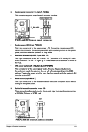
Connect the HDD Activity LED cable to the HDD. • ATX power button/soft-off button (2-pin PWRBTN) This connector is for the system power button. Pressing the power ..., or MPEG card. The IDE LED lights up when you to this connector. CD Right Audio Channel GND GND Left Audio Channel P5KPL-AM SE P5KPL-AM SE Internal audio connector Chapter 1: Product introduction 1-14 PLED+ PLEDPWR GND IDE_LED+ IDE_LED- System panel connector (10-1 pin F_PANEL) This ... stereo audio input from or written to this connector. Pressing the power button turns the system on the BIOS settings.
Connect the HDD Activity LED cable to the HDD. • ATX power button/soft-off button (2-pin PWRBTN) This connector is for the system power button. Pressing the power ..., or MPEG card. The IDE LED lights up when you to this connector. CD Right Audio Channel GND GND Left Audio Channel P5KPL-AM SE P5KPL-AM SE Internal audio connector Chapter 1: Product introduction 1-14 PLED+ PLEDPWR GND IDE_LED+ IDE_LED- System panel connector (10-1 pin F_PANEL) This ... stereo audio input from or written to this connector. Pressing the power button turns the system on the BIOS settings.
User Manual
Page 25
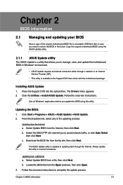
... Open windows, then click Open. 3. Copy the original motherboard BIOS using this utility. Chapter 2 BIOS information 2.1 Managing and updating your BIOS Save a copy of the original motherboard BIOS file to a bootable USB flash disk in case you to manage, save, and update the motherboard BIOS in Windows® environment. • ASUS Update requires an Internet connection either through the...
... Open windows, then click Open. 3. Copy the original motherboard BIOS using this utility. Chapter 2 BIOS information 2.1 Managing and updating your BIOS Save a copy of the original motherboard BIOS file to a bootable USB flash disk in case you to manage, save, and update the motherboard BIOS in Windows® environment. • ASUS Update requires an Internet connection either through the...
User Manual
Page 26
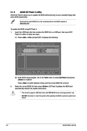
... Flash 2 in either of these two ways: (1) Press + during POST to prevent system boot failure! 2-2 ASUS P5KPL-AM SE Download the latest BIOS file for this motherboard from the ASUS website at www.asus.com. 2.1.2 ASUS EZ Flash 2 utility ASUS EZ Flash 2 allows you to update the BIOS without having to use a bootable floppy disk and a DOS‑based utility.
... Flash 2 in either of these two ways: (1) Press + during POST to prevent system boot failure! 2-2 ASUS P5KPL-AM SE Download the latest BIOS file for this motherboard from the ASUS website at www.asus.com. 2.1.2 ASUS EZ Flash 2 utility ASUS EZ Flash 2 allows you to update the BIOS without having to use a bootable floppy disk and a DOS‑based utility.
User Manual
Page 27
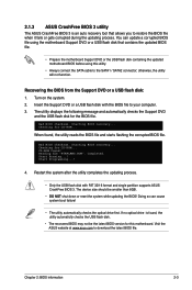
... single partition supports ASUS CrashFree BIOS 3. When found ! Completed. The device size should be the latest BIOS version for CD-ROM... Reading file "P5KPLAMS.ROM". Doing so can update a corrupted BIOS file using this motherboard. 2.1.3 ASUS CrashFree BIOS 3 utility The ASUS CrashFree BIOS 3 is found,... the utility automaticlly checks the USB flash disk. • The recovered BIOS may not be smaller than 8GB. • DO ...
... single partition supports ASUS CrashFree BIOS 3. When found ! Completed. The device size should be the latest BIOS version for CD-ROM... Reading file "P5KPLAMS.ROM". Doing so can update a corrupted BIOS file using this motherboard. 2.1.3 ASUS CrashFree BIOS 3 utility The ASUS CrashFree BIOS 3 is found,... the utility automaticlly checks the USB flash disk. • The recovered BIOS may not be smaller than 8GB. • DO ...
User Manual
Page 28
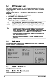
... menu. • The BIOS setup screens in this section are installing a motherboard, reconfiguring your screen. • Visit the ASUS website at www.asus.com to download the latest BIOS file for this motherboard. 2.3 Main menu When you enter the BIOS Setup program, the Main menu... screen appears, giving you to "Run Setup." They may not exactly match what you see on your system, or prompted to set the system date. 2-4 ASUS P5KPL-AM SE...
... menu. • The BIOS setup screens in this section are installing a motherboard, reconfiguring your screen. • Visit the ASUS website at www.asus.com to download the latest BIOS file for this motherboard. 2.3 Main menu When you enter the BIOS Setup program, the Main menu... screen appears, giving you to "Run Setup." They may not exactly match what you see on your system, or prompted to set the system date. 2-4 ASUS P5KPL-AM SE...
User Manual
Page 29
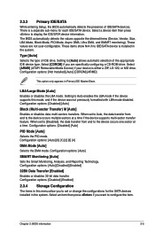
...] [Disabled] [Enabled] 32Bit Data Transfer [Enabled] Enables or disables 32-bit data transfer. 2.3.3 Primary IDE/SATA While entering Setup, the BIOS automatically detects the presence of the appropriate IDE device type. Type [Auto] Selects the type of IDE drive. Configuration options: [Auto] SMART ...Disabled] [Auto] PIO Mode [Auto] Selects the PIO mode. Select an item then press if you are not user-configurable. Chapter 2: BIOS information 2-5 Select a device item then press to configure the item. There is a separate sub-menu for the SATA devices installed in Primary...
...] [Disabled] [Enabled] 32Bit Data Transfer [Enabled] Enables or disables 32-bit data transfer. 2.3.3 Primary IDE/SATA While entering Setup, the BIOS automatically detects the presence of the appropriate IDE device type. Type [Auto] Selects the type of IDE drive. Configuration options: [Auto] SMART ...Disabled] [Auto] PIO Mode [Auto] Selects the PIO mode. Select an item then press if you are not user-configurable. Chapter 2: BIOS information 2-5 Select a device item then press to configure the item. There is a separate sub-menu for the SATA devices installed in Primary...
User Manual
Page 30
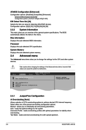
... selection of the Advanced menu items. Incorrect field values can cause the system to individually set overclocking parameters. Test Mode - allows you to malfunction. The BIOS automatically detects the items in this menu. Select either one of the general system specifications. loads the optimal settings for detecting ATA/ATAPI devices. loads... Detect Time Out [35] Selects the time out value for the system. Processor Displays the auto-detected CPU specification. loads overclocking profiles with spread spectrum. 2-6 ASUS P5KPL-AM SE
... selection of the Advanced menu items. Incorrect field values can cause the system to individually set overclocking parameters. Test Mode - allows you to malfunction. The BIOS automatically detects the items in this menu. Select either one of the general system specifications. loads the optimal settings for detecting ATA/ATAPI devices. loads... Detect Time Out [35] Selects the time out value for the system. Processor Displays the auto-detected CPU specification. loads overclocking profiles with spread spectrum. 2-6 ASUS P5KPL-AM SE
User Manual
Page 31
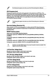
...] [1.4V] 1.5V Over Voltage [Auto] Manually set ICH Chipset Voltage or set to the table below for safe mode. Configuration options: [Auto] [1.5V] [1.6V] Chapter 2: BIOS information 2-7 Overclock Options [Overclock 5%] Allows selection of this happens, revert to the default setting. 1.8V Dual Over Voltage [Auto] Manually set memory voltage or set... the correct Front Side Bus and CPU External Frequency settings. Use the and keys to [Manual]. CPU Frequency [xxx] Displays the frequency sent by the BIOS. The values range from 133 to the system bus and PCI bus.
...] [1.4V] 1.5V Over Voltage [Auto] Manually set ICH Chipset Voltage or set to the table below for safe mode. Configuration options: [Auto] [1.5V] [1.6V] Chapter 2: BIOS information 2-7 Overclock Options [Overclock 5%] Allows selection of this happens, revert to the default setting. 1.8V Dual Over Voltage [Auto] Manually set memory voltage or set... the correct Front Side Bus and CPU External Frequency settings. Use the and keys to [Manual]. CPU Frequency [xxx] Displays the frequency sent by the BIOS. The values range from 133 to the system bus and PCI bus.


