User Manual
Page 3
... 1-2 1.2.1 Motherboard layout 1-2 1.2.2 Layout contents 1-2 1.3 Central Processing Unit (CPU 1-3 1.4 System memory 1-3 1.4.1 Overview 1-3 1.4.2 Memory configurations 1-3 1.5 Expansion slots 1-7 1.5.1 PCI slot 1-7 1.5.2 PCI Express x1 slot 1-7 1.5.3 PCI Express x16 slot 1-7 1.6 Jumpers 1-7 1.7 Connectors 1-9 1.7.1 Rear panel ports 1-9 1.7.2 Internal connectors 1-10 1.8 Software support 1-15 1.8.1 Installing an operating system 1-15 1.8.2 Support DVD information 1-15 Chapter 2: BIOS information 2.1 Managing and updating your BIOS 2-1 2.1.1 ASUS...
... 1-2 1.2.1 Motherboard layout 1-2 1.2.2 Layout contents 1-2 1.3 Central Processing Unit (CPU 1-3 1.4 System memory 1-3 1.4.1 Overview 1-3 1.4.2 Memory configurations 1-3 1.5 Expansion slots 1-7 1.5.1 PCI slot 1-7 1.5.2 PCI Express x1 slot 1-7 1.5.3 PCI Express x16 slot 1-7 1.6 Jumpers 1-7 1.7 Connectors 1-9 1.7.1 Rear panel ports 1-9 1.7.2 Internal connectors 1-10 1.8 Software support 1-15 1.8.1 Installing an operating system 1-15 1.8.2 Support DVD information 1-15 Chapter 2: BIOS information 2.1 Managing and updating your BIOS 2-1 2.1.1 ASUS...
User Manual
Page 8
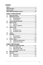
...BIOS 3 ASUS Q-Fan ASUS EZ Flash 2 ASUS MyLogo 2 1 x PS/2 keyboard port 1 x PS/2 mouse port 1 x VGA port 1 x COM 1 x LAN (RJ-45) port 4 x USB 2.0 ports 6-channel audio I/O port (continued on the next page) viii Maximum shared memory of 256 MB - Maximum resolution: 2048 x 1536 x 32 bpp, - P5KPL-AM SE... specifications summary CPU Chipset Front Side Bus Memory Expansion Slots VGA Storage LAN Audio USB ASUS Features Rear panel LGA775 socket for Intel® Core™2 Quad/ Core™2 Extreme /...
...BIOS 3 ASUS Q-Fan ASUS EZ Flash 2 ASUS MyLogo 2 1 x PS/2 keyboard port 1 x PS/2 mouse port 1 x VGA port 1 x COM 1 x LAN (RJ-45) port 4 x USB 2.0 ports 6-channel audio I/O port (continued on the next page) viii Maximum shared memory of 256 MB - Maximum resolution: 2048 x 1536 x 32 bpp, - P5KPL-AM SE... specifications summary CPU Chipset Front Side Bus Memory Expansion Slots VGA Storage LAN Audio USB ASUS Features Rear panel LGA775 socket for Intel® Core™2 Quad/ Core™2 Extreme /...
User Manual
Page 9
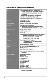
... connector 1 x 24-pin EATXPWR 12 V power connector 1 x 4-pin ATX 12 V power connector 1 x Front panel High Definition audio connector 1 x System Panel connector SFS (Stepless Frequency Selection) - ix FSB turning from 133MHz up to change without notice. P5KPL-AM SE specifications summary Internal connectors ASUS Exclusive Overclocking Features BIOS features Manageability Support DVD contents Accessories Form factor...
... connector 1 x 24-pin EATXPWR 12 V power connector 1 x 4-pin ATX 12 V power connector 1 x Front panel High Definition audio connector 1 x System Panel connector SFS (Stepless Frequency Selection) - ix FSB turning from 133MHz up to change without notice. P5KPL-AM SE specifications summary Internal connectors ASUS Exclusive Overclocking Features BIOS features Manageability Support DVD contents Accessories Form factor...
User Manual
Page 11
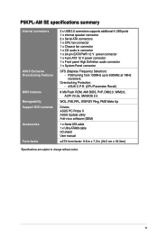
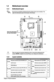
...1. LGA775 socket 3. CD) Optical drive audio connector (4-pin 1-10 13. 1.2 1.2.1 Motherboard overview Motherboard layout Ensure that you install the motherboard into the holes indicated by circles to secure the motherboard to the rear part of the chassis. 24.4cm(9.6in) Place this side towards the...® G31 PCIEX16 RTM870T-954 Super I/O Lithium Cell CMOS Power PCIEX1_1 P5KPL-AM SE SPEAKER Intel® ICH7 ALC662 AAFP F_PANEL CD PCI1 SB_PWR USBPW5-8 USB78 CLRTC USB56 PRI_IDE 8Mb BIOS SATA2 SATA1 Place six screws into the chassis in the correct orientation. Internal...
...1. LGA775 socket 3. CD) Optical drive audio connector (4-pin 1-10 13. 1.2 1.2.1 Motherboard overview Motherboard layout Ensure that you install the motherboard into the holes indicated by circles to secure the motherboard to the rear part of the chassis. 24.4cm(9.6in) Place this side towards the...® G31 PCIEX16 RTM870T-954 Super I/O Lithium Cell CMOS Power PCIEX1_1 P5KPL-AM SE SPEAKER Intel® ICH7 ALC662 AAFP F_PANEL CD PCI1 SB_PWR USBPW5-8 USB78 CLRTC USB56 PRI_IDE 8Mb BIOS SATA2 SATA1 Place six screws into the chassis in the correct orientation. Internal...

User Manual
Page 17
...Real Time Clock (RTC) RAM in CMOS, which include system setup information such as system •words. Hold down and reboot the system, then the BIOS automatically resets the parameter settings to default values. • Due to the chipset limitation, AC power off and on the power supply or unplug and...not need to clear the RTC when the system hangs due to pins 2-3. Turn OFF the computer and unplug the power cord. 2. CLRTC 12 23 P5KPL-AM SE Normal (Default) Clear RTC P5KPL-AM SE Clear RTC RAM Chapter 1: Product introduction 1-8 Keep the cap on CLRTC jumper default position.
...Real Time Clock (RTC) RAM in CMOS, which include system setup information such as system •words. Hold down and reboot the system, then the BIOS automatically resets the parameter settings to default values. • Due to the chipset limitation, AC power off and on the power supply or unplug and...not need to clear the RTC when the system hangs due to pins 2-3. Turn OFF the computer and unplug the power cord. 2. CLRTC 12 23 P5KPL-AM SE Normal (Default) Clear RTC P5KPL-AM SE Clear RTC RAM Chapter 1: Product introduction 1-8 Keep the cap on CLRTC jumper default position.
User Manual
Page 18
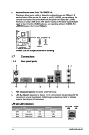
...Data activity Data activity Status OFF OFF Orange Speed LED Description No link 10M 100M ACT/LINK SPEED LED LED LAN port 1-9 ASUS P5KPL-AM SE This feature requires an ATX power supply that can wake up feature. Supported by Realtek 10/100 LAN controller, this jumper to enable or disable the ...keyboard/mouse and USB port 5-6 wake-up the computer by pressing a key on the +5VSB lead, and a corresponding setting in the BIOS. When ...
...Data activity Data activity Status OFF OFF Orange Speed LED Description No link 10M 100M ACT/LINK SPEED LED LED LAN port 1-9 ASUS P5KPL-AM SE This feature requires an ATX power supply that can wake up feature. Supported by Realtek 10/100 LAN controller, this jumper to enable or disable the ...keyboard/mouse and USB port 5-6 wake-up the computer by pressing a key on the +5VSB lead, and a corresponding setting in the BIOS. When ...
User Manual
Page 21
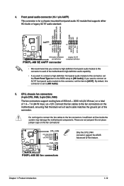
... FAN PWR GND CHA_FAN Rotation +12V GND P5KPL-AM SE fan connectors Only the CPU_FAN connector support the ASUS Advanced Q-Fan feature. Chapter 1: Product introduction 1-12 Front panel audio connector (10-1 pin AAFP) This connector is set the Front Panel Type item in the BIOS setup to [AC97]. CPU, chassis fan connectors... that supports either HD Audio or legacy AC'97 audio standard. Insufficient air flow inside the system may damage the motherboard components. if you want to connect an AC'97 front panel audio module to this connector is for a chassis-mounted front panel audio I/O...
... FAN PWR GND CHA_FAN Rotation +12V GND P5KPL-AM SE fan connectors Only the CPU_FAN connector support the ASUS Advanced Q-Fan feature. Chapter 1: Product introduction 1-12 Front panel audio connector (10-1 pin AAFP) This connector is set the Front Panel Type item in the BIOS setup to [AC97]. CPU, chassis fan connectors... that supports either HD Audio or legacy AC'97 audio standard. Insufficient air flow inside the system may damage the motherboard components. if you want to connect an AC'97 front panel audio module to this connector is for a chassis-mounted front panel audio I/O...
User Manual
Page 23
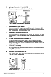
... is in sleep or soft-off the system power. 9. CD Right Audio Channel GND GND Left Audio Channel P5KPL-AM SE P5KPL-AM SE Internal audio connector Chapter 1: Product introduction 1-14 System panel connector (10-1 pin F_PANEL) This connector supports several... card. PLED+ PLEDPWR GND IDE_LED+ IDE_LED- The IDE LED lights up when you to the HDD. • ATX power button/soft-off button (2-pin PWRBTN) This connector is for the chassis-mounted reset button for system reboot without... drive audio connector (4-pin CD) These connectors allow you turn on the BIOS settings.
... is in sleep or soft-off the system power. 9. CD Right Audio Channel GND GND Left Audio Channel P5KPL-AM SE P5KPL-AM SE Internal audio connector Chapter 1: Product introduction 1-14 System panel connector (10-1 pin F_PANEL) This connector supports several... card. PLED+ PLEDPWR GND IDE_LED+ IDE_LED- The IDE LED lights up when you to the HDD. • ATX power button/soft-off button (2-pin PWRBTN) This connector is for the chassis-mounted reset button for system reboot without... drive audio connector (4-pin CD) These connectors allow you turn on the BIOS settings.
User Manual
Page 26
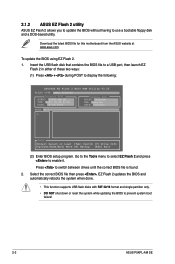
... either of these two ways: (1) Press + during POST to prevent system boot failure! 2-2 ASUS P5KPL-AM SE Download the latest BIOS file for this motherboard from the ASUS website at www.asus.com. Select the correct BIOS file then press , EZ Flash 2 updates the BIOS and automatically reboots the system when done. • This function supports USB flash disks...
... either of these two ways: (1) Press + during POST to prevent system boot failure! 2-2 ASUS P5KPL-AM SE Download the latest BIOS file for this motherboard from the ASUS website at www.asus.com. Select the correct BIOS file then press , EZ Flash 2 updates the BIOS and automatically reboots the system when done. • This function supports USB flash disks...
User Manual
Page 28
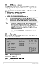
... section 2.8 Exit menu. • The BIOS setup screens in this motherboard. 2.3 Main menu When you enter the BIOS Setup program, the Main menu screen appears, giving you an overview of the following procedures: • Restart using this motherboard apply to most conditions to set the system date. 2-4 ASUS P5KPL-AM SE They may not exactly match what...
... section 2.8 Exit menu. • The BIOS setup screens in this motherboard. 2.3 Main menu When you enter the BIOS Setup program, the Main menu screen appears, giving you an overview of the following procedures: • Restart using this motherboard apply to most conditions to set the system date. 2-4 ASUS P5KPL-AM SE They may not exactly match what...
User Manual
Page 30
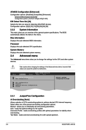
... menu. Select either one of the general system specifications. loads overclocking profiles with spread spectrum. 2-6 ASUS P5KPL-AM SE Test Mode - loads overclock (overclocking 5%) with optimal parameters for the CPU and other system devices. Bios Information Displays the auto-detected BIOS information. Overclock Profile - loads the optimal settings for detecting ATA/ATAPI devices. Configuration options...
... menu. Select either one of the general system specifications. loads overclocking profiles with spread spectrum. 2-6 ASUS P5KPL-AM SE Test Mode - loads overclock (overclocking 5%) with optimal parameters for the CPU and other system devices. Bios Information Displays the auto-detected BIOS information. Overclock Profile - loads the optimal settings for detecting ATA/ATAPI devices. Configuration options...
User Manual
Page 32
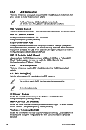
...Configuration options: [FullSpeed ] [HiSpeed ] 2.4.3 CPU Configuration The items in this menu allows you to boot legacy operating systems that the BIOS automatically detects. C1É Support [Enabled] Enable this item to change the configuration of USB devices at startup. Configuration options: [...State" function. USB Functions [Enabled] Allows you to change the USB-related features. Configuration options: [Disabled] [Enabled] 2-8 ASUS P5KPL-AM SE 2.4.2 USB Configuration The items in this menu show the auto-detected values. If no USB device is set in ratio numbers ...
...Configuration options: [FullSpeed ] [HiSpeed ] 2.4.3 CPU Configuration The items in this menu allows you to boot legacy operating systems that the BIOS automatically detects. C1É Support [Enabled] Enable this item to change the configuration of USB devices at startup. Configuration options: [...State" function. USB Functions [Enabled] Allows you to change the USB-related features. Configuration options: [Disabled] [Enabled] 2-8 ASUS P5KPL-AM SE 2.4.2 USB Configuration The items in this menu show the auto-detected values. If no USB device is set in ratio numbers ...
User Manual
Page 34
...[No] When set the audio controller. Configuration options: [Yes] [No] Palette Snooping [Disabled] When set to [Yes], BIOS assigns an IRQ to Enabled. Configuration options: [Disabled] [Enabled] 2-10 ASUS P5KPL-AM SE Configuration options: [32] [64] [96] [128] [160] [192] [224] [248] Allocate IRQ to PCI VGA... [Yes] When set to [No], BIOS configures all the devices in units of the PCI PnP menu items...
...[No] When set the audio controller. Configuration options: [Yes] [No] Palette Snooping [Disabled] When set to [Yes], BIOS assigns an IRQ to Enabled. Configuration options: [Disabled] [Enabled] 2-10 ASUS P5KPL-AM SE Configuration options: [32] [64] [96] [128] [160] [192] [224] [248] Allocate IRQ to PCI VGA... [Yes] When set to [No], BIOS configures all the devices in units of the PCI PnP menu items...
User Manual
Page 38
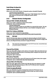
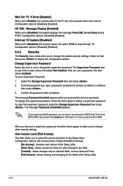
...key to be pressed when error occurs. Configuration options: [Disabled] [Enabled] 2.6.3 Security The Security menu items allow you successfully set your BIOS password, you set a password, this item shows Installed. The Supervisor Password item on how to erase the RTC RAM. From the password...to change other items appear to allow change the supervisor password, follow the same steps in the Setup utility. 2-14 ASUS P5KPL-AM SE The message Password uninstalled appears. Change Supervisor Password Select this function allows the option ROMs to trap Interrupt 19. Select...
...key to be pressed when error occurs. Configuration options: [Disabled] [Enabled] 2.6.3 Security The Security menu items allow you successfully set your BIOS password, you set a password, this item shows Installed. The Supervisor Password item on how to erase the RTC RAM. From the password...to change other items appear to allow change the supervisor password, follow the same steps in the Setup utility. 2-14 ASUS P5KPL-AM SE The message Password uninstalled appears. Change Supervisor Password Select this function allows the option ROMs to trap Interrupt 19. Select...
User Manual
Page 40
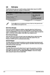
...one of the parameters on even when the PC is turned off. When you selected are finished making your changes to the BIOS items. Main Advanced BIOS SETUP UTILITY Power Boot Tools Exit Exit Options Exit & Save Changes Exit & Discard Changes Discard Changes Load Setup Defaults Exit ...Select Exit & Save Changes or make other than System Date, System Time, and Password, the BIOS asks for a confirmation before saving the values to the non-volatile RAM. 2-16 ASUS P5KPL-AM SE Discard Changes This option allows you to discard the selections you made and restore the previously saved...
...one of the parameters on even when the PC is turned off. When you selected are finished making your changes to the BIOS items. Main Advanced BIOS SETUP UTILITY Power Boot Tools Exit Exit Options Exit & Save Changes Exit & Discard Changes Discard Changes Load Setup Defaults Exit ...Select Exit & Save Changes or make other than System Date, System Time, and Password, the BIOS asks for a confirmation before saving the values to the non-volatile RAM. 2-16 ASUS P5KPL-AM SE Discard Changes This option allows you to discard the selections you made and restore the previously saved...


