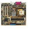
Motherboard DIY Troubleshooting Guide
Page 15
P4BP-MX 2.0 P4BP-MX 2.0 Onboard LED SB_PWR ON Standby Power OFF Powered Off 1-5
Motherboard DIY Troubleshooting Guide
Page 27
ATX_POWER1 Pin 1 +12.0VDC +5VSB ATX12V1 PWR_OK COM P4BP-MX 2.0 +12V DC GND +12V DC GND +5.0VDC COM +5.0VDC COM +3.3VDC P4BP-MX 2.0 ATX Power Connectors +3.3VDC +5.0VDC +5.0VDC -5.0VDC COM COM COM PS_ON# COM -12.0VDC +3.3VDC Left Audio Channel Ground Ground Right Audio Channel Left Audio Channel Ground Ground Right Audio Channel P4BP-MX 2.0 CD(Black) AUX(White) P4BP-MX 2.0 Internal Audio Connectors 1-17
Motherboard DIY Troubleshooting Guide
Page 28
CPU_FAN Rotation +12V GND P4BP-MX 2.0 CHA_FAN Rotation +12V GND P4BP-MX 2.0 12-Volt Cooling Fan Power USB+5V LDM5 LDP5 GND NC USB+5V LDM6 LDP6 GND P4BP-MX 2.0 P4BP-MX 2.0 USB 2.0 Header USB56 1 1-18
Motherboard DIY Troubleshooting Guide
Page 31
P4BP-MX 2.0 IR_CON PX GND IRRX +5V P4BP-MX 2.0 Infrared Module Connector PIN 1 COM2 P4BP-MX 2.0 P4BP-MX 2.0 Serial COM2 Bracket 1-21
P4BP-MX 2.0 user's manual
Page 3
Features Contents Notices v Safety information vi About this guide vii Conventions used in this guide vii Typography vii P4BP-MX 2.0 specifications summary viii Chapter 1: Product introduction 1.1 Welcome 1-2 1.2 Package contents 1-2 1.3 Special features 1-3 1.3.1 Product Highlights 1-3 1.3.2 Unique ASUS features 1-4 1.4 Before you proceed 1-5 1.5 Motherboard overview 1-6 1.5.1 Motherboard layout 1-6 1.5.2 Placement direction 1-7 1.5.3 Screw holes 1-7 1.6 Central Processing Unit (CPU 1-8 1.6.1 Overview 1-8 1.6.2 Installing the...
P4BP-MX 2.0 user's manual
Page 8
P4BP-MX 2.0 specifications summary CPU Chipset Front System Bus Memory Expansion slots Storage Audio LAN USB Special features Rear Panel I/O Internal I/O connectors ` viii Socket 478 for Intel...® ALC655 6-channel CODEC Supports S/PDIF Out interface Realtek® 8100C integrated 10/100Mbps LAN controller Maximum of six (6) USB 2.0 ports ASUS JumperFree ASUS C.P.R. (CPU Parameter Recall) ASUS CrashFree BIOS ASUS EZ Flash ASUS MyLogo™ Power Loss Restart STR (Suspend-to-RAM) CPU Throttle 1 x Parallel port 1 x Serial port 1 x VGA port 1 x PS/2 Keyboard port 1 x PS...
P4BP-MX 2.0 user's manual
Page 12
... Thank you ahead in your package with the list below. 1.2 Package contents Check your motherboard package for the following items. ASUS P4BP-MX 2.0 motherboard ASUS motherboard support CD 1 x IDE cable 1 x Floppy disk cable I/O shield Bag of extra jumper caps User guide If any of... ASUS quality motherboards! Supporting up to set a new benchmark for buying the ASUS® P4BP-MX 2.0 motherboard! The motherboard combines the powers of the Intel® Pentium® 4 processor and the Intel...
P4BP-MX 2.0 user's manual
Page 13
.... 6 USB 2.0 ports The motherboard implements the new Universal Serial Bus (USB) 2.0 specification, extending the connection speed from 12 Mbps on USB 1.1 to powerful speaker systems. ASUS P4BP-MX 2.0 motherboard 1-3 The motherboard also supports the Intel® Hyper-Threading Technology. USB 2.0 is the Realtek® ALC655 AC'97 CODEC. This motherboard supports 533/400...
P4BP-MX 2.0 user's manual
Page 15
... the system chassis. 3. Hold components by power LED. Use a grounded wrist strap or touch a safely grounded object or discharge any component. 2. P4BP-MX 2.0 P4BP-MX 2.0 Onboard LED SB_PWR ON Standby Power OFF Powered Off ASUS P4BP-MX 2.0 motherboard 1-5 Whenever you uninstall any motherboard settings. 1. Onboard LED The motherboard comes with the component. 5. 1.4 Before you proceed Take note...
P4BP-MX 2.0 user's manual
Page 16
... Top:Line In Center:Line Out Below:Mic In FP_AUDIO Intel 82845GV Memory Controller Hub 01 23 SEC_IDE PRI_ IDE 3Mbit Firmware Hub RTL8100C PCI1 P4BP-MX 2.0 PCI2 Intel 82801DB ICH4 Audio Codec SPDIF_OUT CD PCI3 CHA_FAN AUX SB_PWR COM2 USBPWR_56 USB56 GAME1 CLRTC BUZZ PLED CHASSIS F_PANEL USBPWR_12 3 2 2 1 +5V (Default) +5VSB...
P4BP-MX 2.0 user's manual
Page 17
1.5.2 Placement direction When installing the motherboard, make sure that you place it into the chassis in the image below. 1.5.3 Screw holes Place six (6) screws into the holes indicated by circles to secure the motherboard to the rear part of the chassis ASUS P4BP-MX 2.0 motherboard 1-7 Place this side towards the rear of the chassis as indicated in the correct orientation. Doing so may damage the motherboard. The edge with external ports goes to the chassis. Do not overtighten the screws!
P4BP-MX 2.0 user's manual
Page 18
... Intel® Pentium® 4 CPUs with a surface mount 478-pin Zero Insertion Force (ZIF) socket designed for the Intel® Pentium® 4 processor. Gold Arrow P4BP-MX 2.0 P4BP-MX 2.0 Socket 478 Incorrect installation of the marked corner (with gold triangle) on the socket to ensure correct installation. Make sure to enable the Hyper-Threading...
P4BP-MX 2.0 user's manual
Page 19
... the CPU above the socket such that the socket lever is in one correct orientation. Carefully insert the CPU into the socket to install a CPU. 1. ASUS P4BP-MX 2.0 motherboard 1-9 Unlock the socket by pressing the lever sideways, then lift it up to indicate that it fits in completely. 3. The lever clicks on the...
P4BP-MX 2.0 user's manual
Page 20
.... 3. DO NOT force a DIMM into a socket to install a DIMM. 1. Firmly insert the DIMM into the DIMM sockets of the DDR DIMM sockets. 80 Pins P4BP-MX 2.0 104 Pins P4BP-MX 2.0 184-Pin DDR DIMM Sockets Make sure to unplug the power supply before adding or removing DIMMs or other system components. Failure to do...
P4BP-MX 2.0 user's manual
Page 21
... LAN - Onboard Audio - Onboard VGA shared When using PCI cards on the system and change the necessary BIOS settings, if any. Refer to the card. ASUS P4BP-MX 2.0 motherboard 1-11 See Chapter 2 for this motherboard A B C D E F G H PCI slot 1 - - - - - Install an expansion card following the instructions that the cards do not need IRQ assignments...
P4BP-MX 2.0 user's manual
Page 23
... so BIOS can clear the CMOS memory of date, time, and system setup parameters by the onboard button cell battery. P4BP-MX 2.0 CLRTC 12 23 Clear CMOS Normal (Default) P4BP-MX 2.0 Clear RTC RAM You do not need to clear the RTC when the system hangs due to re-enter data. ...Removing the cap will cause system boot failure! 1.9 Jumpers 1. Shut down the key during the boot process and enter BIOS setup to overclocking. ASUS P4BP-MX 2.0 motherboard 1-13 Clear RTC RAM (CLRTC) This jumper allows you to its previous values. Move the jumper cap from pins 2-3 (default) to pins...
P4BP-MX 2.0 user's manual
Page 24
... when you wish to wake up from S1 sleep mode (CPU stopped, DRAM refreshed, system running in the BIOS. P4BP-MX 2.0 KBPWR 2 1 +5V 3 2 +5V (Default) P4BP-MX 2.0 Keyboard Power Setting 3. USB device wake-up (3-pin USBPWR_12, USBPWR_34, USBPWR_56) Set these jumpers to +5V to...that can provide 500mA on the keyboard. USBPWR_12 3 2 2 1 +5V (Default) +5VSB USBPWR_34 3 2 2 1 +5V (Default) +5VSB P4BP-MX 2.0 USBPWR_56 12 23 +5V P4BP-MX 2.0 USB Device Wake Up (Default) +5VSB • The USB device wake-up . • The total current consumed must NOT exceed the power...
P4BP-MX 2.0 user's manual
Page 25
..., a scanner, or other audio sources. This Line Out (lime) jack connects a headphone or a speaker. This port connects to a Local Area Network (LAN) through a network hub. 4. ASUS P4BP-MX 2.0 motherboard 1-15 Serial connector. Line Out jack. USB 2.0 ports 3 and 4. 1.10 Connectors This section describes and illustrates the motherboard rear panel and internal connectors. 1.10...