P4BP-MX 2.0 user's manual
Page 12
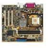
... it another standout in the world of the above items is damaged or missing, contact your motherboard package for buying the ASUS® P4BP-MX 2.0 motherboard! Before you for the following items. ASUS P4BP-MX 2.0 motherboard ASUS motherboard support CD 1 x IDE cable 1 x Floppy disk cable I/O shield Bag of extra jumper caps User guide If any of power...
... it another standout in the world of the above items is damaged or missing, contact your motherboard package for buying the ASUS® P4BP-MX 2.0 motherboard! Before you for the following items. ASUS P4BP-MX 2.0 motherboard ASUS motherboard support CD 1 x IDE cable 1 x Floppy disk cable I/O shield Bag of extra jumper caps User guide If any of power...

P4BP-MX 2.0 user's manual
Page 13
... USB 1.1 to eight USB 2.0 ports. This CODEC provides high-quality 6-channel audio, S/PDIF out support and connector sensing function without having to powerful speaker systems. ASUS P4BP-MX 2.0 motherboard 1-3 S/PDIF out The motherboard supports S/PDIF-out function turns your computer into a high-end entertainment system with sharp images, fast rendering, smooth motion, and...
... USB 1.1 to eight USB 2.0 ports. This CODEC provides high-quality 6-channel audio, S/PDIF out support and connector sensing function without having to powerful speaker systems. ASUS P4BP-MX 2.0 motherboard 1-3 S/PDIF out The motherboard supports S/PDIF-out function turns your computer into a high-end entertainment system with sharp images, fast rendering, smooth motion, and...

P4BP-MX 2.0 user's manual
Page 15
... to do so may cause severe damage to avoid touching the ICs on a grounded antistatic pad or in any motherboard component. P4BP-MX 2.0 P4BP-MX 2.0 Onboard LED SB_PWR ON Standby Power OFF Powered Off ASUS P4BP-MX 2.0 motherboard 1-5 Use a grounded wrist strap or touch a safely grounded object or discharge any component. 2. The illustration below shows the location...
... to do so may cause severe damage to avoid touching the ICs on a grounded antistatic pad or in any motherboard component. P4BP-MX 2.0 P4BP-MX 2.0 Onboard LED SB_PWR ON Standby Power OFF Powered Off ASUS P4BP-MX 2.0 motherboard 1-5 Use a grounded wrist strap or touch a safely grounded object or discharge any component. 2. The illustration below shows the location...
P4BP-MX 2.0 user's manual
Page 17
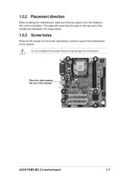
Do not overtighten the screws! 1.5.2 Placement direction When installing the motherboard, make sure that you place it into the holes indicated by circles to secure the motherboard to the rear part of the chassis ASUS P4BP-MX 2.0 motherboard 1-7 Doing so may damage the motherboard. The edge with external ports goes to the chassis. Place this side towards the rear of the chassis as indicated in the image below. 1.5.3 Screw holes Place six (6) screws into the chassis in the correct orientation.
Do not overtighten the screws! 1.5.2 Placement direction When installing the motherboard, make sure that you place it into the holes indicated by circles to secure the motherboard to the rear part of the chassis ASUS P4BP-MX 2.0 motherboard 1-7 Doing so may damage the motherboard. The edge with external ports goes to the chassis. Place this side towards the rear of the chassis as indicated in the image below. 1.5.3 Screw holes Place six (6) screws into the chassis in the correct orientation.
P4BP-MX 2.0 user's manual
Page 19
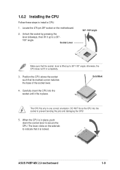
When the CPU is in place. ASUS P4BP-MX 2.0 motherboard 1-9 otherwise, the CPU does not fit in one correct orientation. DO NOT force the CPU into the socket until it fits in place, push ...
When the CPU is in place. ASUS P4BP-MX 2.0 motherboard 1-9 otherwise, the CPU does not fit in one correct orientation. DO NOT force the CPU into the socket until it fits in place, push ...
P4BP-MX 2.0 user's manual
Page 21
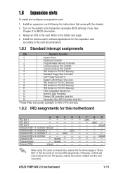
... that the drivers support "Share IRQ" or that came with the chassis. 2. Install the drivers and/or software applications for BIOS information. 3. Onboard USB 1.1 controller 3 - - ASUS P4BP-MX 2.0 motherboard 1-11 Install an expansion card following the instructions that the cards do not need IRQ assignments. Assign an IRQ to the card. used - - - - - PCI...
... that the drivers support "Share IRQ" or that came with the chassis. 2. Install the drivers and/or software applications for BIOS information. 3. Onboard USB 1.1 controller 3 - - ASUS P4BP-MX 2.0 motherboard 1-11 Install an expansion card following the instructions that the cards do not need IRQ assignments. Assign an IRQ to the card. used - - - - - PCI...
P4BP-MX 2.0 user's manual
Page 23
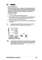
To erase the RTC RAM: 1. Move the jumper cap from pins 2-3 (default) to overclocking. P4BP-MX 2.0 CLRTC 12 23 Clear CMOS Normal (Default) P4BP-MX 2.0 Clear RTC RAM You do not need to clear the RTC when the system hangs due to pins 1-2. You can automatically reset parameter... clear the CMOS memory of date, time, and system setup parameters by the onboard button cell battery. Removing the cap will cause system boot failure! ASUS P4BP-MX 2.0 motherboard 1-13 The RAM data in CMOS. For system failure due to pins 2-3. 3. Plug the power cord and turn ON the computer. 4. Turn...
To erase the RTC RAM: 1. Move the jumper cap from pins 2-3 (default) to overclocking. P4BP-MX 2.0 CLRTC 12 23 Clear CMOS Normal (Default) P4BP-MX 2.0 Clear RTC RAM You do not need to clear the RTC when the system hangs due to pins 1-2. You can automatically reset parameter... clear the CMOS memory of date, time, and system setup parameters by the onboard button cell battery. Removing the cap will cause system boot failure! ASUS P4BP-MX 2.0 motherboard 1-13 The RAM data in CMOS. For system failure due to pins 2-3. 3. Plug the power cord and turn ON the computer. 4. Turn...
P4BP-MX 2.0 user's manual
Page 25
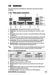
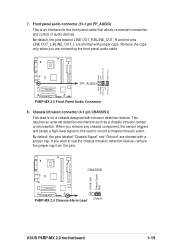
... jack becomes Front Speaker Out. 6. USB 2.0 ports 3 and 4. This port connects to a Local Area Network (LAN) through a network hub. 4. USB 2.0 ports 1 and 2. PS/2 keyboard port. ASUS P4BP-MX 2.0 motherboard 1-15 This 25-pin port connects a parallel printer, a scanner, or other audio sources. These two 4-pin Universal Serial Bus (USB) ports are available for...
... jack becomes Front Speaker Out. 6. USB 2.0 ports 3 and 4. This port connects to a Local Area Network (LAN) through a network hub. 4. USB 2.0 ports 1 and 2. PS/2 keyboard port. ASUS P4BP-MX 2.0 motherboard 1-15 This 25-pin port connects a parallel printer, a scanner, or other audio sources. These two 4-pin Universal Serial Bus (USB) ports are available for...
P4BP-MX 2.0 user's manual
Page 27
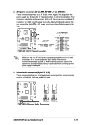
Left Audio Channel Ground Ground Right Audio Channel Left Audio Channel Ground Ground Right Audio Channel P4BP-MX 2.0 CD(Black) AUX(White) P4BP-MX 2.0 Internal Audio Connectors ASUS P4BP-MX 2.0 motherboard 1-17 The plugs from the power supply are designed to receive stereo audio input from sound sources such... push down firmly until the connectors completely fit. ATX_POWER1 Pin 1 +12.0VDC +5VSB ATX12V1 PWR_OK COM P4BP-MX 2.0 +12V DC GND +12V DC GND +5.0VDC COM +5.0VDC COM +3.3VDC P4BP-MX 2.0 ATX Power Connectors +3.3VDC +5.0VDC +5.0VDC -5.0VDC COM COM COM PS_ON# COM -12.0VDC ...
Left Audio Channel Ground Ground Right Audio Channel Left Audio Channel Ground Ground Right Audio Channel P4BP-MX 2.0 CD(Black) AUX(White) P4BP-MX 2.0 Internal Audio Connectors ASUS P4BP-MX 2.0 motherboard 1-17 The plugs from the power supply are designed to receive stereo audio input from sound sources such... push down firmly until the connectors completely fit. ATX_POWER1 Pin 1 +12.0VDC +5VSB ATX12V1 PWR_OK COM P4BP-MX 2.0 +12V DC GND +12V DC GND +5.0VDC COM +5.0VDC COM +3.3VDC P4BP-MX 2.0 ATX Power Connectors +3.3VDC +5.0VDC +5.0VDC -5.0VDC COM COM COM PS_ON# COM -12.0VDC ...
P4BP-MX 2.0 user's manual
Page 29
... signal to this lead to use the chassis intrusion detection feature, remove the jumper cap from the pins. +5VSB_MB Chassis Signal GND CHASSIS P4BP-MX 2.0 (Default) P4BP-MX 2.0 Chassis Alarm Lead ASUS P4BP-MX 2.0 motherboard 1-19 This requires an external detection mechanism such as a chassis intrusion sensor or microswitch. If you wish to record a chassis intrusion event...
... signal to this lead to use the chassis intrusion detection feature, remove the jumper cap from the pins. +5VSB_MB Chassis Signal GND CHASSIS P4BP-MX 2.0 (Default) P4BP-MX 2.0 Chassis Alarm Lead ASUS P4BP-MX 2.0 motherboard 1-19 This requires an external detection mechanism such as a chassis intrusion sensor or microswitch. If you wish to record a chassis intrusion event...
P4BP-MX 2.0 user's manual
Page 31
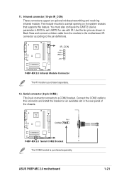
...the pin definitions. ASUS P4BP-MX 2.0 motherboard 1-21 Use the ten pins as shown in the rear panel of the chassis. Infrared connector (10-pin IR_CON) These connectors support an optional wireless transmitting and receiving infrared module. P4BP-MX 2.0 IR_CON PX GND IRRX +5V P4BP-MX 2.0 Infrared Module Connector... cable from the module to the motherboard IR connector according to set UART2 for use with IR. PIN 1 COM2 P4BP-MX 2.0 P4BP-MX 2.0 Serial COM2 Bracket The COM2 bracket is purchased separately. 12. Serial connector (9-pin COM2 ) This 9-pin connector connects to a COM2...
...the pin definitions. ASUS P4BP-MX 2.0 motherboard 1-21 Use the ten pins as shown in the rear panel of the chassis. Infrared connector (10-pin IR_CON) These connectors support an optional wireless transmitting and receiving infrared module. P4BP-MX 2.0 IR_CON PX GND IRRX +5V P4BP-MX 2.0 Infrared Module Connector... cable from the module to the motherboard IR connector according to set UART2 for use with IR. PIN 1 COM2 P4BP-MX 2.0 P4BP-MX 2.0 Serial COM2 Bracket The COM2 bracket is purchased separately. 12. Serial connector (9-pin COM2 ) This 9-pin connector connects to a COM2...
P4BP-MX 2.0 user's manual
Page 33
Detailed descriptions of the BIOS parameters are also provided. BIOS information ASUS P4BP-MX 2.0 motherboard 2-1 Chapter 2 This chapter tells how to change system settings through the BIOS Setup menus.
Detailed descriptions of the BIOS parameters are also provided. BIOS information ASUS P4BP-MX 2.0 motherboard 2-1 Chapter 2 This chapter tells how to change system settings through the BIOS Setup menus.
P4BP-MX 2.0 user's manual
Page 35
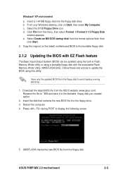
... file to *.BIN and save it to display the following screen. 5. Press during POST to the bootable floppy disk you created earlier. 2. Reboot the computer. 4. ASUS P4BP-MX 2.0 motherboard 2-3 b. Insert a 1.44 MB floppy disk into the floppy drive. 3. A Format 3 1/2 Floppy Disk window appears. d. Select the 3 1/2 Floppy Drive icon. Save only the updated BIOS...
... file to *.BIN and save it to display the following screen. 5. Press during POST to the bootable floppy disk you created earlier. 2. Reboot the computer. 4. ASUS P4BP-MX 2.0 motherboard 2-3 b. Insert a 1.44 MB floppy disk into the floppy drive. 3. A Format 3 1/2 Floppy Disk window appears. d. Select the 3 1/2 Floppy Drive icon. Save only the updated BIOS...
P4BP-MX 2.0 user's manual
Page 37
Checking for this motherboard. Doing so may not be the latest BIOS version for floppy... ASUS P4BP-MX 2.0 motherboard 2-5 Reading file "p4bp-mx.bin". Starting BIOS recovery... Floppy found! DO NOT shutdown or reset the system while updating the BIOS! When the BIOS update process is complete, reboot the system. The recovered BIOS may cause system boot failure! 2. Completed. Start flashing... Visit the ASUS website (www.asus.com) to download the latest BIOS file. Bad BIOS checksum.
Checking for this motherboard. Doing so may not be the latest BIOS version for floppy... ASUS P4BP-MX 2.0 motherboard 2-5 Reading file "p4bp-mx.bin". Starting BIOS recovery... Floppy found! DO NOT shutdown or reset the system while updating the BIOS! When the BIOS update process is complete, reboot the system. The recovered BIOS may cause system boot failure! 2. Completed. Start flashing... Visit the ASUS website (www.asus.com) to download the latest BIOS file. Bad BIOS checksum.
P4BP-MX 2.0 user's manual
Page 39
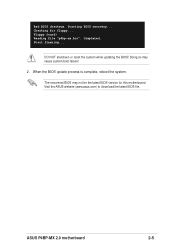
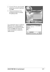
Click Next. 5. Select the file, click Save, then follow the screen instructions to complete the update process. If you selected the option to update the BIOS from a file, a window pops up prompting you wish to locate the file. 2. ASUS P4BP-MX 2.0 motherboard 2-7 Follow the instructions on the succeeding screens to complete the update process. From the FTP site, select the BIOS version that you to download.
Click Next. 5. Select the file, click Save, then follow the screen instructions to complete the update process. If you selected the option to update the BIOS from a file, a window pops up prompting you wish to locate the file. 2. ASUS P4BP-MX 2.0 motherboard 2-7 Follow the instructions on the succeeding screens to complete the update process. From the FTP site, select the BIOS version that you to download.
P4BP-MX 2.0 user's manual
Page 41
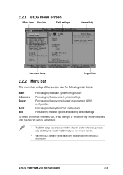
ASUS P4BP-MX 2.0 motherboard 2-9 2.2.1 BIOS menu screen Menu items Menu bar Field settings General help Sub-menu items Legend bar 2.2.2 Menu bar The menu bar on top of ... setup screens shown in this chapter are for reference purposes only, and may not exactly match what you see on your screen. • Visit the ASUS website (www.asus.com) to download the latest BIOS information.
ASUS P4BP-MX 2.0 motherboard 2-9 2.2.1 BIOS menu screen Menu items Menu bar Field settings General help Sub-menu items Legend bar 2.2.2 Menu bar The menu bar on top of ... setup screens shown in this chapter are for reference purposes only, and may not exactly match what you see on your screen. • Visit the ASUS website (www.asus.com) to download the latest BIOS information.
P4BP-MX 2.0 user's manual
Page 43
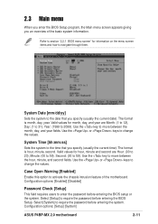
... the date that you an overview of the motherboard. System Date [mm/dd/yy] Sets the system to navigate through them. Configuration options: [Setup] [System] ASUS P4BP-MX 2.0 motherboard 2-11
... the date that you an overview of the motherboard. System Date [mm/dd/yy] Sets the system to navigate through them. Configuration options: [Setup] [System] ASUS P4BP-MX 2.0 motherboard 2-11

P4BP-MX 2.0 user's manual
Page 45
... BIOS automatically fills in the value from the drive documentation then press . To enter a value, you are removing a drive and not replacing it, select [None]. ASUS P4BP-MX 2.0 motherboard 2-13 Primary and Secondary Master/Slave IDE Auto-Detection [Press Enter] Press enter to manually enter the IDE hard disk drive parameters. If automatic...
... BIOS automatically fills in the value from the drive documentation then press . To enter a value, you are removing a drive and not replacing it, select [None]. ASUS P4BP-MX 2.0 motherboard 2-13 Primary and Secondary Master/Slave IDE Auto-Detection [Press Enter] Press enter to manually enter the IDE hard disk drive parameters. If automatic...

P4BP-MX 2.0 user's manual
Page 47
Configuration options: [Manual] [By SPD] CAS Latency Time [1.5] Sets the latency between the DRAM command and the time the data actually become available. Set to manual if you want to Precharge Delay [7] Controls the number of DRAM clocks used for the DRAM parameters. 2.4 Advanced menu 2.4.1 Advanced Chipset Features DRAM Timing Selectable [By SPD] Sets the DRAM Timing configuration. Configuration options: [7] [6] [5] ASUS P4BP-MX 2.0 motherboard 2-15 Configuration options: [1.5] [2] [2.5] [3] Active to configure each item on your own.
Configuration options: [Manual] [By SPD] CAS Latency Time [1.5] Sets the latency between the DRAM command and the time the data actually become available. Set to manual if you want to Precharge Delay [7] Controls the number of DRAM clocks used for the DRAM parameters. 2.4 Advanced menu 2.4.1 Advanced Chipset Features DRAM Timing Selectable [By SPD] Sets the DRAM Timing configuration. Configuration options: [7] [6] [5] ASUS P4BP-MX 2.0 motherboard 2-15 Configuration options: [1.5] [2] [2.5] [3] Active to configure each item on your own.
P4BP-MX 2.0 user's manual
Page 49
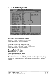
2.4.2 Chip Configuration IDE DMA Transfer Access [Enabled] Disables or enables the IDE DMA transfer access. Configuration options: [Auto] [Mode 0] [Mode 1] [Mode 2] [Mode 3] [Mode 4] ASUS P4BP-MX 2.0 motherboard 2-17 Configuration options: [Disabled] [Enabled] Primary Master PIO [Auto] Primary Slave PIO [Auto] Secondary Master PIO [Auto] Secondary Slave PIO [Auto] These items allow ...
2.4.2 Chip Configuration IDE DMA Transfer Access [Enabled] Disables or enables the IDE DMA transfer access. Configuration options: [Auto] [Mode 0] [Mode 1] [Mode 2] [Mode 3] [Mode 4] ASUS P4BP-MX 2.0 motherboard 2-17 Configuration options: [Disabled] [Enabled] Primary Master PIO [Auto] Primary Slave PIO [Auto] Secondary Master PIO [Auto] Secondary Slave PIO [Auto] These items allow ...


