Motherboard DIY Troubleshooting Guide
Page 1
P4BP-MX 2.0 Motherboard
P4BP-MX 2.0 Motherboard
P4BP-MX 2.0 user's manual
Page 1
Motherboard P4BP-MX 2.0 User Guide
Motherboard P4BP-MX 2.0 User Guide

P4BP-MX 2.0 user's manual
Page 3
... Notices v Safety information vi About this guide vii Conventions used in this guide vii Typography vii P4BP-MX 2.0 specifications summary viii Chapter 1: Product introduction 1.1 Welcome 1-2 1.2 Package contents 1-2 1.3 Special features 1-3 1.3.1 Product Highlights 1-3 1.3.2 Unique ASUS features 1-4 1.4 Before you proceed 1-5 1.5 Motherboard overview 1-6 1.5.1 Motherboard layout 1-6 1.5.2 Placement direction 1-7 1.5.3 Screw holes 1-7 1.6 Central Processing Unit (CPU 1-8 1.6.1 Overview 1-8 1.6.2 Installing the CPU 1-9 1.7 System memory...
... Notices v Safety information vi About this guide vii Conventions used in this guide vii Typography vii P4BP-MX 2.0 specifications summary viii Chapter 1: Product introduction 1.1 Welcome 1-2 1.2 Package contents 1-2 1.3 Special features 1-3 1.3.1 Product Highlights 1-3 1.3.2 Unique ASUS features 1-4 1.4 Before you proceed 1-5 1.5 Motherboard overview 1-6 1.5.1 Motherboard layout 1-6 1.5.2 Placement direction 1-7 1.5.3 Screw holes 1-7 1.6 Central Processing Unit (CPU 1-8 1.6.1 Overview 1-8 1.6.2 Installing the CPU 1-9 1.7 System memory...
P4BP-MX 2.0 user's manual
Page 6
... sure about the voltage of the electrical outlet you add a device. • Before connecting or removing signal cables from the motherboard, ensure that your retailer. Operation safety • Before installing the motherboard and adding devices on a stable surface. • If you encounter technical problems with the package. • Before using the product...
... sure about the voltage of the electrical outlet you add a device. • Before connecting or removing signal cables from the motherboard, ensure that your retailer. Operation safety • Before installing the motherboard and adding devices on a stable surface. • If you encounter technical problems with the package. • Before using the product...
P4BP-MX 2.0 user's manual
Page 11
Product introduction It includes brief descriptions of the motherboard components, and illustrations of the motherboard. Chapter 1 This chapter describes the features of the layout, jumper settings, and connectors.
Product introduction It includes brief descriptions of the motherboard components, and illustrations of the motherboard. Chapter 1 This chapter describes the features of the layout, jumper settings, and connectors.
P4BP-MX 2.0 user's manual
Page 12
...Package contents Check your retailer. 1-2 Chapter 1: Product introduction The motherboard combines the powers of the Intel® Pentium® 4 processor and the Intel® 845GV chipset to 2GB of ASUS quality motherboards! 1.1 Welcome! Supporting up to set a new benchmark for ... standout in the world of the above items is damaged or missing, contact your motherboard package for buying the ASUS® P4BP-MX 2.0 motherboard! Before you for the following items. ASUS P4BP-MX 2.0 motherboard ASUS motherboard support CD 1 x IDE cable 1 x Floppy disk cable I/O shield Bag of...
...Package contents Check your retailer. 1-2 Chapter 1: Product introduction The motherboard combines the powers of the Intel® Pentium® 4 processor and the Intel® 845GV chipset to 2GB of ASUS quality motherboards! 1.1 Welcome! Supporting up to set a new benchmark for ... standout in the world of the above items is damaged or missing, contact your motherboard package for buying the ASUS® P4BP-MX 2.0 motherboard! Before you for the following items. ASUS P4BP-MX 2.0 motherboard ASUS motherboard support CD 1 x IDE cable 1 x Floppy disk cable I/O shield Bag of...

P4BP-MX 2.0 user's manual
Page 13
...2.0 specification, extending the connection speed from 12 Mbps on USB 1.1 to powerful speaker systems. ASUS P4BP-MX 2.0 motherboard 1-3 supporting up to buy advanced sound cards. S/PDIF out The motherboard supports S/PDIF-out function turns your computer into a high-end entertainment system with USB 1.1.... cameras, next generation scanners and printers, and fast storage units. 1.3 Special features 1.3.1 Product Highlights Latest processor technology The motherboard comes with a 478-pin surface mount, Zero Insertion Force (ZIF) socket for the Intel® Pentium® 4 ...
...2.0 specification, extending the connection speed from 12 Mbps on USB 1.1 to powerful speaker systems. ASUS P4BP-MX 2.0 motherboard 1-3 supporting up to buy advanced sound cards. S/PDIF out The motherboard supports S/PDIF-out function turns your computer into a high-end entertainment system with USB 1.1.... cameras, next generation scanners and printers, and fast storage units. 1.3 Special features 1.3.1 Product Highlights Latest processor technology The motherboard comes with a 478-pin surface mount, Zero Insertion Force (ZIF) socket for the Intel® Pentium® 4 ...

P4BP-MX 2.0 user's manual
Page 14
...to open the system chassis and clear the RTC data. See page 2-3. ASUS MyLogo™ This new feature present in the motherboard allows you to personalize and add style to overclocking. feature of the motherboard BIOS allows automatic re-setting to the BIOS previous settings in case the ...data froma bootable floppy disk in case the system hangs due to your system with customizable boot logos. See page 2-27. 1.3.2 Unique ASUS features CrashFree BIOS This feature allows you to overclocking, C.P.R. With EZ Flash, you can easily update the system BIOS even before loading the...
...to open the system chassis and clear the RTC data. See page 2-3. ASUS MyLogo™ This new feature present in the motherboard allows you to personalize and add style to overclocking. feature of the motherboard BIOS allows automatic re-setting to the BIOS previous settings in case the ...data froma bootable floppy disk in case the system hangs due to your system with customizable boot logos. See page 2-27. 1.3.2 Unique ASUS features CrashFree BIOS This feature allows you to overclocking, C.P.R. With EZ Flash, you can easily update the system BIOS even before loading the...

P4BP-MX 2.0 user's manual
Page 15
... install or remove any static electricity by touching the metal surface of the system chassis. 3. Unplug the power cord from the power supply. P4BP-MX 2.0 P4BP-MX 2.0 Onboard LED SB_PWR ON Standby Power OFF Powered Off ASUS P4BP-MX 2.0 motherboard 1-5 When lit, this green LED indicates that the system is detached from the wall socket before touching any...
... install or remove any static electricity by touching the metal surface of the system chassis. 3. Unplug the power cord from the power supply. P4BP-MX 2.0 P4BP-MX 2.0 Onboard LED SB_PWR ON Standby Power OFF Powered Off ASUS P4BP-MX 2.0 motherboard 1-5 When lit, this green LED indicates that the system is detached from the wall socket before touching any...

P4BP-MX 2.0 user's manual
Page 16
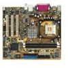
... Power LED Power Button PLED+ PLEDPWR GND IDE_LED+ IDE_LED- Ground Reset NC IDE_LED Reset 1-6 Chapter 1: Product introduction 1.5 Motherboard overview 1.5.1 Motherboard layout PS/2KBMS T: Mouse B: Keyboard COM1 Socket 478 CPU_FAN Super I/O IR_CON DDR DIMM1 (64/72 bit, 184-pin... In Center:Line Out Below:Mic In FP_AUDIO Intel 82845GV Memory Controller Hub 01 23 SEC_IDE PRI_ IDE 3Mbit Firmware Hub RTL8100C PCI1 P4BP-MX 2.0 PCI2 Intel 82801DB ICH4 Audio Codec SPDIF_OUT CD PCI3 CHA_FAN AUX SB_PWR COM2 USBPWR_56 USB56 GAME1 CLRTC BUZZ PLED CHASSIS F_PANEL USBPWR_12...
... Power LED Power Button PLED+ PLEDPWR GND IDE_LED+ IDE_LED- Ground Reset NC IDE_LED Reset 1-6 Chapter 1: Product introduction 1.5 Motherboard overview 1.5.1 Motherboard layout PS/2KBMS T: Mouse B: Keyboard COM1 Socket 478 CPU_FAN Super I/O IR_CON DDR DIMM1 (64/72 bit, 184-pin... In Center:Line Out Below:Mic In FP_AUDIO Intel 82845GV Memory Controller Hub 01 23 SEC_IDE PRI_ IDE 3Mbit Firmware Hub RTL8100C PCI1 P4BP-MX 2.0 PCI2 Intel 82801DB ICH4 Audio Codec SPDIF_OUT CD PCI3 CHA_FAN AUX SB_PWR COM2 USBPWR_56 USB56 GAME1 CLRTC BUZZ PLED CHASSIS F_PANEL USBPWR_12...
P4BP-MX 2.0 user's manual
Page 17
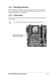
1.5.2 Placement direction When installing the motherboard, make sure that you place it into the holes indicated by circles to secure the motherboard to the rear part of the chassis ASUS P4BP-MX 2.0 motherboard 1-7 Doing so may damage the motherboard. The edge with external ports goes to the chassis. Place this side towards the rear of the chassis as indicated in the image below. 1.5.3 Screw holes Place six (6) screws into the chassis in the correct orientation. Do not overtighten the screws!
1.5.2 Placement direction When installing the motherboard, make sure that you place it into the holes indicated by circles to secure the motherboard to the rear part of the chassis ASUS P4BP-MX 2.0 motherboard 1-7 Doing so may damage the motherboard. The edge with external ports goes to the chassis. Place this side towards the rear of the chassis as indicated in the image below. 1.5.3 Screw holes Place six (6) screws into the chassis in the correct orientation. Do not overtighten the screws!
P4BP-MX 2.0 user's manual
Page 18
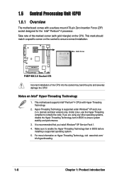
...Technology, visit www.intel.com/ info/hyperthreading. 1-8 Chapter 1: Product introduction This motherboard supports Intel® Pentium® 4 CPUs with a surface mount 478-pin Zero Insertion Force (ZIF) socket designed for the Intel® Pentium® 4 processor. Gold Arrow P4BP-MX 2.0 P4BP-MX 2.0 Socket 478 Incorrect installation of the marked corner (with gold triangle) on...installation. Take note of the CPU into the socket may bend the pins and severely damage the CPU! 1.6 Central Processing Unit (CPU) 1.6.1 Overview The motherboard comes with Hyper-Threading Technology. 2.
...Technology, visit www.intel.com/ info/hyperthreading. 1-8 Chapter 1: Product introduction This motherboard supports Intel® Pentium® 4 CPUs with a surface mount 478-pin Zero Insertion Force (ZIF) socket designed for the Intel® Pentium® 4 processor. Gold Arrow P4BP-MX 2.0 P4BP-MX 2.0 Socket 478 Incorrect installation of the marked corner (with gold triangle) on...installation. Take note of the CPU into the socket may bend the pins and severely damage the CPU! 1.6 Central Processing Unit (CPU) 1.6.1 Overview The motherboard comes with Hyper-Threading Technology. 2.
P4BP-MX 2.0 user's manual
Page 19
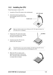
Unlock the socket by pressing the lever sideways, then lift it is locked. ASUS P4BP-MX 2.0 motherboard 1-9 Carefully insert the CPU into the socket to secure the CPU. 1.6.2 Installing the CPU Follow these steps to 90°-100° angle; DO NOT ... fits only in completely. 3. Socket Lever 90º~100º angle Make sure that the socket lever is in place. The lever clicks on the motherboard. 2. When the CPU is lifted up to indicate that its marked corner matches the base of the socket lever. otherwise, the CPU does not fit...
Unlock the socket by pressing the lever sideways, then lift it is locked. ASUS P4BP-MX 2.0 motherboard 1-9 Carefully insert the CPU into the socket to secure the CPU. 1.6.2 Installing the CPU Follow these steps to 90°-100° angle; DO NOT ... fits only in completely. 3. Socket Lever 90º~100º angle Make sure that the socket lever is in place. The lever clicks on the motherboard. 2. When the CPU is lifted up to indicate that its marked corner matches the base of the socket lever. otherwise, the CPU does not fit...
P4BP-MX 2.0 user's manual
Page 20
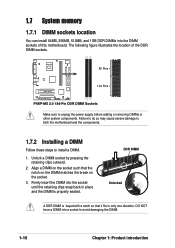
The following figure illustrates the location of this motherboard. DO NOT force a DIMM into the DIMM sockets of the DDR DIMM sockets. 80 Pins P4BP-MX 2.0 104 Pins P4BP-MX 2.0 184-Pin DDR DIMM Sockets Make sure to unplug the power supply before adding or removing DIMMs or other system components. Unlock a DIMM socket by ... 1GB DDR DIMMs into a socket to avoid damaging the DIMM. 1-10 Chapter 1: Product introduction Failure to do so may cause severe damage to both the motherboard and the components. 1.7.2 Installing a DIMM Follow these steps to install a DIMM. 1.
The following figure illustrates the location of this motherboard. DO NOT force a DIMM into the DIMM sockets of the DDR DIMM sockets. 80 Pins P4BP-MX 2.0 104 Pins P4BP-MX 2.0 184-Pin DDR DIMM Sockets Make sure to unplug the power supply before adding or removing DIMMs or other system components. Unlock a DIMM socket by ... 1GB DDR DIMMs into a socket to avoid damaging the DIMM. 1-10 Chapter 1: Product introduction Failure to do so may cause severe damage to both the motherboard and the components. 1.7.2 Installing a DIMM Follow these steps to install a DIMM. 1.
P4BP-MX 2.0 user's manual
Page 21
... between the two PCI groups, making the system unstable and the card inoperable. PCI slot 3 shared Onboard USB 1.1 controller 1shared Onboard USB 1.1 controller 2 - - - Onboard Audio - ASUS P4BP-MX 2.0 motherboard 1-11 Refer to the tables next page. 4. PCI slot 2 - - - - - - used - - - - - shared - - - - - - Install an expansion card following the instructions that the cards do not need IRQ...
... between the two PCI groups, making the system unstable and the card inoperable. PCI slot 3 shared Onboard USB 1.1 controller 1shared Onboard USB 1.1 controller 2 - - - Onboard Audio - ASUS P4BP-MX 2.0 motherboard 1-11 Refer to the tables next page. 4. PCI slot 2 - - - - - - used - - - - - shared - - - - - - Install an expansion card following the instructions that the cards do not need IRQ...
P4BP-MX 2.0 user's manual
Page 23
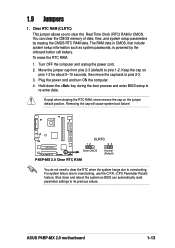
... such as system passwords, is powered by erasing the CMOS RTC RAM data. P4BP-MX 2.0 CLRTC 12 23 Clear CMOS Normal (Default) P4BP-MX 2.0 Clear RTC RAM You do not need to clear the RTC when the system hangs due to pins 2-3. 3. ASUS P4BP-MX 2.0 motherboard 1-13 Keep the cap on the jumper default position. For system failure...
... such as system passwords, is powered by erasing the CMOS RTC RAM data. P4BP-MX 2.0 CLRTC 12 23 Clear CMOS Normal (Default) P4BP-MX 2.0 Clear RTC RAM You do not need to clear the RTC when the system hangs due to pins 2-3. 3. ASUS P4BP-MX 2.0 motherboard 1-13 Keep the cap on the jumper default position. For system failure...
P4BP-MX 2.0 user's manual
Page 25
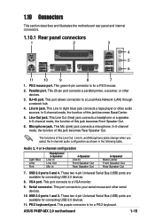
...In Line Out Mic In 4-Speaker Line In Front Speaker Out Rear Speaker Out 6-Speaker Bass/Center Front Speaker Out Rear Speaker Out 7. VGA port. ASUS P4BP-MX 2.0 motherboard 1-15 Line Out jack. In 6-channel mode, the function of the Line Out, Line In, and Microphone jacks change when you select the 6-... (USB) ports are available for connecting USB 2.0 devices. 11. This port connects to a VGA monitor. 9. 1.10 Connectors This section describes and illustrates the motherboard rear panel and internal connectors. 1.10.1 Rear panel connectors 1 2 3 4 5 6 11 10 9 8 7 1.
...In Line Out Mic In 4-Speaker Line In Front Speaker Out Rear Speaker Out 6-Speaker Bass/Center Front Speaker Out Rear Speaker Out 7. VGA port. ASUS P4BP-MX 2.0 motherboard 1-15 Line Out jack. In 6-channel mode, the function of the Line Out, Line In, and Microphone jacks change when you select the 6-... (USB) ports are available for connecting USB 2.0 devices. 11. This port connects to a VGA monitor. 9. 1.10 Connectors This section describes and illustrates the motherboard rear panel and internal connectors. 1.10.1 Rear panel connectors 1 2 3 4 5 6 11 10 9 8 7 1.
P4BP-MX 2.0 user's manual
Page 26
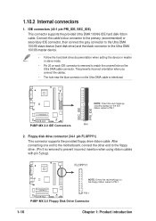
...to match the covered hole on the Ultra DMA cable is removed to the floppy drive. (Pin 5 is intentional. P4BP-MX 2.0 IDE Connectors PIN 1 2. P4BP-MX 2.0 PIN 1 P4BP-MX 2.0 Floppy Disk Drive Connector 1-16 Chapter 1: Product introduction IDE connectors (40-1 pin PRI_IDE, SEC_IDE) This connector ...connector on the Ultra DMA cable connector. After connecting one end to the motherboard, connect the other end to prevent incorrect insertion when using ribbon cables with pin 5 plug). SEC_IDE PRI_IDE P4BP-MX 2.0 NOTE: Orient the red markings (usually zigzag) on the floppy ...
...to match the covered hole on the Ultra DMA cable is removed to the floppy drive. (Pin 5 is intentional. P4BP-MX 2.0 IDE Connectors PIN 1 2. P4BP-MX 2.0 PIN 1 P4BP-MX 2.0 Floppy Disk Drive Connector 1-16 Chapter 1: Product introduction IDE connectors (40-1 pin PRI_IDE, SEC_IDE) This connector ...connector on the Ultra DMA cable connector. After connecting one end to the motherboard, connect the other end to prevent incorrect insertion when using ribbon cables with pin 5 plug). SEC_IDE PRI_IDE P4BP-MX 2.0 NOTE: Orient the red markings (usually zigzag) on the floppy ...
P4BP-MX 2.0 user's manual
Page 27
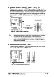
... push down firmly until the connectors completely fit. ATX_POWER1 Pin 1 +12.0VDC +5VSB ATX12V1 PWR_OK COM P4BP-MX 2.0 +12V DC GND +12V DC GND +5.0VDC COM +5.0VDC COM +3.3VDC P4BP-MX 2.0 ATX Power Connectors +3.3VDC +5.0VDC +5.0VDC -5.0VDC COM COM COM PS_ON# COM -12.0VDC +3.... configured system. Left Audio Channel Ground Ground Right Audio Channel Left Audio Channel Ground Ground Right Audio Channel P4BP-MX 2.0 CD(Black) AUX(White) P4BP-MX 2.0 Internal Audio Connectors ASUS P4BP-MX 2.0 motherboard 1-17 The plugs from sound sources such as a CD-ROM, TV tuner, or MPEG card.
... push down firmly until the connectors completely fit. ATX_POWER1 Pin 1 +12.0VDC +5VSB ATX12V1 PWR_OK COM P4BP-MX 2.0 +12V DC GND +12V DC GND +5.0VDC COM +5.0VDC COM +3.3VDC P4BP-MX 2.0 ATX Power Connectors +3.3VDC +5.0VDC +5.0VDC -5.0VDC COM COM COM PS_ON# COM -12.0VDC +3.... configured system. Left Audio Channel Ground Ground Right Audio Channel Left Audio Channel Ground Ground Right Audio Channel P4BP-MX 2.0 CD(Black) AUX(White) P4BP-MX 2.0 Internal Audio Connectors ASUS P4BP-MX 2.0 motherboard 1-17 The plugs from sound sources such as a CD-ROM, TV tuner, or MPEG card.
P4BP-MX 2.0 user's manual
Page 28
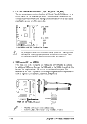
... sure that the black wire of each cable matches the ground pin of the connector. You may damage the motherboard components. 5. The module has two USB 2.0 ports for additional USB ports. CPU and chassis fan connectors (3-pin CPU_FAN, CHA_FAN) The fan connectors support cooling fans... place jumper caps on the rear panel are not jumpers! Lack of 1A~2.22A (26.64W max.) at +12V. USB+5V LDM5 LDP5 GND NC P4BP-MX 2.0 P4BP-MX 2.0 USB 2.0 Header USB56 1 USB+5V LDM6 LDP6 GND • The USB 2.0 module is available for connecting next generation USB peripherals such as high resolution ...
... sure that the black wire of each cable matches the ground pin of the connector. You may damage the motherboard components. 5. The module has two USB 2.0 ports for additional USB ports. CPU and chassis fan connectors (3-pin CPU_FAN, CHA_FAN) The fan connectors support cooling fans... place jumper caps on the rear panel are not jumpers! Lack of 1A~2.22A (26.64W max.) at +12V. USB+5V LDM5 LDP5 GND NC P4BP-MX 2.0 P4BP-MX 2.0 USB 2.0 Header USB56 1 USB+5V LDM6 LDP6 GND • The USB 2.0 module is available for connecting next generation USB peripherals such as high resolution ...


