
Motherboard DIY Troubleshooting Guide
Page 36
Starting BIOS recovery... Checking for floppy... 2-4 Bad BIOS checksum.
Starting BIOS recovery... Checking for floppy... 2-4 Bad BIOS checksum.
Motherboard DIY Troubleshooting Guide
Page 37
Floppy found! Start flashing... 2-5 Reading file "1016BPMX.BIN". Starting BIOS recovery... Completed. Checking for floppy... Bad BIOS checksum.
Floppy found! Start flashing... 2-5 Reading file "1016BPMX.BIN". Starting BIOS recovery... Completed. Checking for floppy... Bad BIOS checksum.
P4BP-MX 2.0 user's manual
Page 4
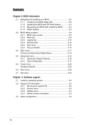
Safeguards Contents Chapter 2: BIOS information 2.1 Managing and updating your BIOS 2-2 2.1.1 Creating a bootable floppy disk 2-2 2.1.2 Updating the BIOS with EZ Flash feature 2-3 2.1.3 Recovering the BIOS with CrashFree BIOS .......... 2-4 2.1.4 ASUS Update 2-6 2.2 BIOS Setup program 2-8 2.2.1 BIOS menu screen 2-9 2.2.2 Menu bar 2-9 2.2.3 Legend bar 2-10 2.2.4 General help 2-10 2.2.5 Sub-... system 3-2 3.2 Support CD information 3-2 3.2.1 Running the support CD 3-2 3.2.2 Drivers menu 3-3 3.2.3 Utilities menu 3-3 3.2.4 ASUS Contact Information 3-4 3.3 Audio configuration 3-5 iv
Safeguards Contents Chapter 2: BIOS information 2.1 Managing and updating your BIOS 2-2 2.1.1 Creating a bootable floppy disk 2-2 2.1.2 Updating the BIOS with EZ Flash feature 2-3 2.1.3 Recovering the BIOS with CrashFree BIOS .......... 2-4 2.1.4 ASUS Update 2-6 2.2 BIOS Setup program 2-8 2.2.1 BIOS menu screen 2-9 2.2.2 Menu bar 2-9 2.2.3 Legend bar 2-10 2.2.4 General help 2-10 2.2.5 Sub-... system 3-2 3.2 Support CD information 3-2 3.2.1 Running the support CD 3-2 3.2.2 Drivers menu 3-3 3.2.3 Utilities menu 3-3 3.2.4 ASUS Contact Information 3-4 3.3 Audio configuration 3-5 iv
P4BP-MX 2.0 user's manual
Page 8
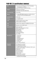
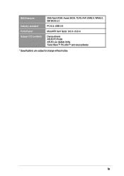
P4BP-MX 2.0 specifications summary CPU Chipset Front System Bus Memory Expansion slots Storage Audio LAN USB Special features Rear Panel I/O Internal I/O connectors ` viii Socket 478 for Intel&#... Realtek® ALC655 6-channel CODEC Supports S/PDIF Out interface Realtek® 8100C integrated 10/100Mbps LAN controller Maximum of six (6) USB 2.0 ports ASUS JumperFree ASUS C.P.R. (CPU Parameter Recall) ASUS CrashFree BIOS ASUS EZ Flash ASUS MyLogo™ Power Loss Restart STR (Suspend-to-RAM) CPU Throttle 1 x Parallel port 1 x Serial port 1 x VGA port 1 x PS/2 Keyboard port 1 x PS...
P4BP-MX 2.0 specifications summary CPU Chipset Front System Bus Memory Expansion slots Storage Audio LAN USB Special features Rear Panel I/O Internal I/O connectors ` viii Socket 478 for Intel&#... Realtek® ALC655 6-channel CODEC Supports S/PDIF Out interface Realtek® 8100C integrated 10/100Mbps LAN controller Maximum of six (6) USB 2.0 ports ASUS JumperFree ASUS C.P.R. (CPU Parameter Recall) ASUS CrashFree BIOS ASUS EZ Flash ASUS MyLogo™ Power Loss Restart STR (Suspend-to-RAM) CPU Throttle 1 x Parallel port 1 x Serial port 1 x VGA port 1 x PS/2 Keyboard port 1 x PS...
P4BP-MX 2.0 user's manual
Page 9
ix BIOS features Industry standard Form Factor Support CD contents 3Mb Flash ROM, Award BIOS, TCAV, PnP, DMI2.0, WfM2.0, SM BIOS 2.3 PCI 2.2, USB 2.0 MicroATX form factor: 9.6 in x 8.6 in Device drivers ASUS PC Probe ASUS Live Update Utility Trend Micro™ PC-cillin™ anti-virus software * Specifications are subject to change without notice.
ix BIOS features Industry standard Form Factor Support CD contents 3Mb Flash ROM, Award BIOS, TCAV, PnP, DMI2.0, WfM2.0, SM BIOS 2.3 PCI 2.2, USB 2.0 MicroATX form factor: 9.6 in x 8.6 in Device drivers ASUS PC Probe ASUS Live Update Utility Trend Micro™ PC-cillin™ anti-virus software * Specifications are subject to change without notice.

P4BP-MX 2.0 user's manual
Page 14
...in case the system hangs due to restore the original BIOS data froma bootable floppy disk in case the BIOS codes and data are corrupted. ASUS EZ Flash BIOS The ASUS EZ Flash feature works through the Award BIOS Update utility. When the system hangs due to open ...boot logos. This protection eliminates the need to overclocking, C.P.R. C.P.R. (CPU Parameter Recall) The C.P.R. 1.3.2 Unique ASUS features CrashFree BIOS This feature allows you can easily update the system BIOS even before loading the operating system. See page 2-7. See page 2-27. Simply shut down and reboot the ...
...in case the system hangs due to restore the original BIOS data froma bootable floppy disk in case the BIOS codes and data are corrupted. ASUS EZ Flash BIOS The ASUS EZ Flash feature works through the Award BIOS Update utility. When the system hangs due to open ...boot logos. This protection eliminates the need to overclocking, C.P.R. C.P.R. (CPU Parameter Recall) The C.P.R. 1.3.2 Unique ASUS features CrashFree BIOS This feature allows you can easily update the system BIOS even before loading the operating system. See page 2-7. See page 2-27. Simply shut down and reboot the ...
P4BP-MX 2.0 user's manual
Page 18
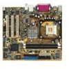
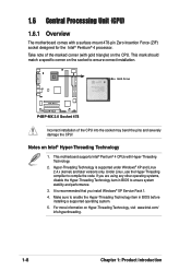
... the CPU! Hyper-Threading Technology is recommended that you are using any other operating systems, disable the Hyper-Threading Technology item in BIOS before installing a supported operating system. 5. Gold Arrow P4BP-MX 2.0 P4BP-MX 2.0 Socket 478 Incorrect installation of the marked corner (with gold triangle) on the socket to ensure correct installation. This mark should...
... the CPU! Hyper-Threading Technology is recommended that you are using any other operating systems, disable the Hyper-Threading Technology item in BIOS before installing a supported operating system. 5. Gold Arrow P4BP-MX 2.0 P4BP-MX 2.0 Socket 478 Incorrect installation of the marked corner (with gold triangle) on the socket to ensure correct installation. This mark should...
P4BP-MX 2.0 user's manual
Page 21
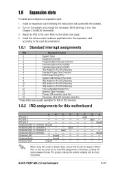
...cards on the system and change the necessary BIOS settings, if any. 1.8 Expansion slots To install and configure an expansion card: 1. See Chapter 2 for this motherboard A B C D E F G H PCI slot 1 - - - - - Refer to the card. PCI slot 3 shared Onboard USB 1.1 controller 1shared Onboard USB 1.1 controller 2 - - - used - - ASUS P4BP-MX 2.0 motherboard 1-11 Turn on shared slots,... (dual fifo) 15 Secondary Ultra ATA Controller (dual fifo) *These IRQs are usually available for ISA or PCI devices. 1.8.2 IRQ assignments for BIOS information. 3.
...cards on the system and change the necessary BIOS settings, if any. 1.8 Expansion slots To install and configure an expansion card: 1. See Chapter 2 for this motherboard A B C D E F G H PCI slot 1 - - - - - Refer to the card. PCI slot 3 shared Onboard USB 1.1 controller 1shared Onboard USB 1.1 controller 2 - - - used - - ASUS P4BP-MX 2.0 motherboard 1-11 Turn on shared slots,... (dual fifo) 15 Secondary Ultra ATA Controller (dual fifo) *These IRQs are usually available for ISA or PCI devices. 1.8.2 IRQ assignments for BIOS information. 3.
P4BP-MX 2.0 user's manual
Page 23
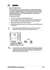
... the cap on the jumper default position. P4BP-MX 2.0 CLRTC 12 23 Clear CMOS Normal (Default) P4BP-MX 2.0 Clear RTC RAM You do not need to clear the RTC when the system hangs due to pins 2-3. 3. ASUS P4BP-MX 2.0 motherboard 1-13 Turn OFF the computer and... unplug the power cord. 2. Except when clearing the RTC RAM, never remove the cap on pins 1-2 for about 5~10 seconds, then move the cap back to overclocking. 1.9 Jumpers 1. The RAM data in CMOS. Shut down the key during the boot process and enter BIOS...
... the cap on the jumper default position. P4BP-MX 2.0 CLRTC 12 23 Clear CMOS Normal (Default) P4BP-MX 2.0 Clear RTC RAM You do not need to clear the RTC when the system hangs due to pins 2-3. 3. ASUS P4BP-MX 2.0 motherboard 1-13 Turn OFF the computer and... unplug the power cord. 2. Except when clearing the RTC RAM, never remove the cap on pins 1-2 for about 5~10 seconds, then move the cap back to overclocking. 1.9 Jumpers 1. The RAM data in CMOS. Shut down the key during the boot process and enter BIOS...

P4BP-MX 2.0 user's manual
Page 24
... supply capability (+5VSB) whether under normal condition or in the BIOS. This feature requires an ATX power supply that can supply at least 1A on the +5V lead, and a corresponding setting in sleep mode. 1-14 Chapter 1: Product introduction P4BP-MX 2.0 KBPWR 2 1 +5V 3 2 +5V (Default) P4BP-MX 2.0 Keyboard Power Setting 3. Otherwise, the system would not power...
... supply capability (+5VSB) whether under normal condition or in the BIOS. This feature requires an ATX power supply that can supply at least 1A on the +5V lead, and a corresponding setting in sleep mode. 1-14 Chapter 1: Product introduction P4BP-MX 2.0 KBPWR 2 1 +5V 3 2 +5V (Default) P4BP-MX 2.0 Keyboard Power Setting 3. Otherwise, the system would not power...
P4BP-MX 2.0 user's manual
Page 31
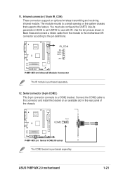
... connectors support an optional wireless transmitting and receiving infrared module. P4BP-MX 2.0 IR_CON PX GND IRRX +5V P4BP-MX 2.0 Infrared Module Connector The IR module is purchased separately. ASUS P4BP-MX 2.0 motherboard 1-21 Use the ten pins as shown in the rear panel of the chassis. PIN 1 COM2 P4BP-MX 2.0 P4BP-MX 2.0 Serial COM2 Bracket The COM2 bracket is purchased separately... connector (9-pin COM2 ) This 9-pin connector connects to set UART2 for use with IR. 11. You must also configure the UART2 Use As parameter in BIOS to a COM2 bracket.
... connectors support an optional wireless transmitting and receiving infrared module. P4BP-MX 2.0 IR_CON PX GND IRRX +5V P4BP-MX 2.0 Infrared Module Connector The IR module is purchased separately. ASUS P4BP-MX 2.0 motherboard 1-21 Use the ten pins as shown in the rear panel of the chassis. PIN 1 COM2 P4BP-MX 2.0 P4BP-MX 2.0 Serial COM2 Bracket The COM2 bracket is purchased separately... connector (9-pin COM2 ) This 9-pin connector connects to set UART2 for use with IR. 11. You must also configure the UART2 Use As parameter in BIOS to a COM2 bracket.
P4BP-MX 2.0 user's manual
Page 32
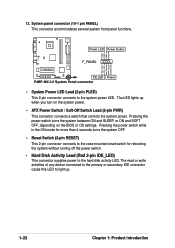
Power LED Power Button F_PANEL P4BP-MX 2.0 IDE_LED Reset P4BP-MX 2.0 System Panel connector • System Power LED Lead (2-pin PLED) This 2-pin connector connects to the hard disk activity LED. System panel connector (10-1 pin ... or write activities of any device connected to the primary or secondary IDE connector cause this LED to light up when you turn on the BIOS or OS settings. Pressing the power switch turns the system between ON and SLEEP, or ON and SOFT OFF, depending on the system power. •...
Power LED Power Button F_PANEL P4BP-MX 2.0 IDE_LED Reset P4BP-MX 2.0 System Panel connector • System Power LED Lead (2-pin PLED) This 2-pin connector connects to the hard disk activity LED. System panel connector (10-1 pin ... or write activities of any device connected to the primary or secondary IDE connector cause this LED to light up when you turn on the BIOS or OS settings. Pressing the power switch turns the system between ON and SLEEP, or ON and SOFT OFF, depending on the system power. •...
P4BP-MX 2.0 user's manual
Page 33
Chapter 2 This chapter tells how to change system settings through the BIOS Setup menus. BIOS information ASUS P4BP-MX 2.0 motherboard 2-1 Detailed descriptions of the BIOS parameters are also provided.
Chapter 2 This chapter tells how to change system settings through the BIOS Setup menus. BIOS information ASUS P4BP-MX 2.0 motherboard 2-1 Detailed descriptions of the BIOS parameters are also provided.

P4BP-MX 2.0 user's manual
Page 34
...in case you do not have a copy of the original motherboard BIOS file in a floppy disk. • Visit the ASUS website and download the latest BIOS file for this motherboard is recommended that updates the BIOS using a floppy disk during POST.) 2. DOS environment Insert a... floppy disk. Do either one of the original motherboard BIOS file to restore the BIOS in Windows® environment.) Refer to manage and update the motherboard Basic Input/Output System (BIOS) setup. 1. ASUS CrashFree BIOS (Updates the BIOS using the ASUS Update utility. 2.1.1 Creating a bootable floppy disk 1. ...
...in case you do not have a copy of the original motherboard BIOS file in a floppy disk. • Visit the ASUS website and download the latest BIOS file for this motherboard is recommended that updates the BIOS using a floppy disk during POST.) 2. DOS environment Insert a... floppy disk. Do either one of the original motherboard BIOS file to restore the BIOS in Windows® environment.) Refer to manage and update the motherboard Basic Input/Output System (BIOS) setup. 1. ASUS CrashFree BIOS (Updates the BIOS using the ASUS Update utility. 2.1.1 Creating a bootable floppy disk 1. ...
P4BP-MX 2.0 user's manual
Page 35
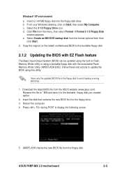
..., click on Start, then select My Computer. Click File from the ASUS website (www.asus.com). Download the latest BIOS file from the menu, then select Format. Insert the disk that contains the new BIOS file into the floppy disk drive. Select the 3 1/2 Floppy Drive ... a. Insert a 1.44 MB floppy disk into the floppy drive. 3. Press during POST to the bootable floppy disk. 2.1.2 Updating the BIOS with the executable Flash Memory Writer Utility (AWDFLASH.EXE). AWDFLASH checks the new BIOS file from the format options field, then click Start. 2. ASUS P4BP-MX 2.0 motherboard 2-3
..., click on Start, then select My Computer. Click File from the ASUS website (www.asus.com). Download the latest BIOS file from the menu, then select Format. Insert the disk that contains the new BIOS file into the floppy disk drive. Select the 3 1/2 Floppy Drive ... a. Insert a 1.44 MB floppy disk into the floppy drive. 3. Press during POST to the bootable floppy disk. 2.1.2 Updating the BIOS with the executable Flash Memory Writer Utility (AWDFLASH.EXE). AWDFLASH checks the new BIOS file from the format options field, then click Start. 2. ASUS P4BP-MX 2.0 motherboard 2-3

P4BP-MX 2.0 user's manual
Page 36
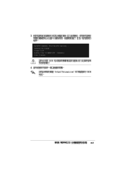
... the motherboard fails or gets corrupted. 1. When a corrupted BIOS is copied, the computer returns to restore the BIOS. Bad BIOS checksum. Insert a floppy disk that contains the motherboard BIOS before proceeding with CrashFree BIOS The CrashFree BIOS auto recovery tool allows you may also use this motherboard. 2-4 Chapter 2: BIOS information Prepare a floppy disk that contains the original...
... the motherboard fails or gets corrupted. 1. When a corrupted BIOS is copied, the computer returns to restore the BIOS. Bad BIOS checksum. Insert a floppy disk that contains the motherboard BIOS before proceeding with CrashFree BIOS The CrashFree BIOS auto recovery tool allows you may also use this motherboard. 2-4 Chapter 2: BIOS information Prepare a floppy disk that contains the original...
P4BP-MX 2.0 user's manual
Page 37
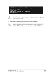
Floppy found! Checking for this motherboard. Reading file "p4bp-mx.bin". Doing so may not be the latest BIOS version for floppy... Start flashing... Bad BIOS checksum. Visit the ASUS website (www.asus.com) to download the latest BIOS file. ASUS P4BP-MX 2.0 motherboard 2-5 The recovered BIOS may cause system boot failure! 2. Completed. Starting BIOS recovery... DO NOT shutdown or reset the system while updating the BIOS! When the BIOS update process is complete, reboot the system.
Floppy found! Checking for this motherboard. Reading file "p4bp-mx.bin". Doing so may not be the latest BIOS version for floppy... Start flashing... Bad BIOS checksum. Visit the ASUS website (www.asus.com) to download the latest BIOS file. ASUS P4BP-MX 2.0 motherboard 2-5 The recovered BIOS may cause system boot failure! 2. Completed. Starting BIOS recovery... DO NOT shutdown or reset the system while updating the BIOS! When the BIOS update process is complete, reboot the system.
P4BP-MX 2.0 user's manual
Page 38
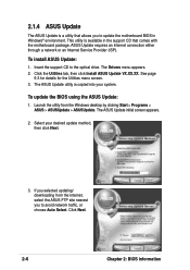
...; environment. The ASUS Update initial screen appears. 2. ASUS Update requires an Internet connection either through a network or an Internet Service Provider (ISP). Click Next. 2-6 Chapter 2: BIOS information The Drivers menu appears. 2. Select your system. Insert the support CD to update the motherboard BIOS in the support... CD that allows you to the optical drive. If you to avoid network traffic, or choose Auto Select. Launch the utility from the Internet, select the ASUS FTP site nearest you selected updating/ ...
...; environment. The ASUS Update initial screen appears. 2. ASUS Update requires an Internet connection either through a network or an Internet Service Provider (ISP). Click Next. 2-6 Chapter 2: BIOS information The Drivers menu appears. 2. Select your system. Insert the support CD to update the motherboard BIOS in the support... CD that allows you to the optical drive. If you to avoid network traffic, or choose Auto Select. Launch the utility from the Internet, select the ASUS FTP site nearest you selected updating/ ...
P4BP-MX 2.0 user's manual
Page 39
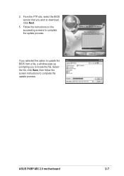
Follow the instructions on the succeeding screens to complete the update process. Click Next. 5. If you selected the option to update the BIOS from a file, a window pops up prompting you wish to locate the file. ASUS P4BP-MX 2.0 motherboard 2-7 2. Select the file, click Save, then follow the screen instructions to complete the update process. From the FTP site, select the BIOS version that you to download.
Follow the instructions on the succeeding screens to complete the update process. Click Next. 5. If you selected the option to update the BIOS from a file, a window pops up prompting you wish to locate the file. ASUS P4BP-MX 2.0 motherboard 2-7 2. Select the file, click Save, then follow the screen instructions to complete the update process. From the FTP site, select the BIOS version that you to download.
P4BP-MX 2.0 user's manual
Page 40
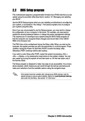
... this program. Do this utility. Select the Load Optimized Settings item under the Exit Menu. See section "2.7 Exit menu." 2-8 Chapter 2: BIOS information Even if you are installing a motherboard, reconfiguring your system using the navigation keys. Press during the Power-On Self Test (POST)... to configure your system, or prompted to "Run Setup". 2.2 BIOS Setup program This motherboard supports a programmable firmware hub (FHW) chip that the computer can recognize these changes and record them in the CMOS...
... this program. Do this utility. Select the Load Optimized Settings item under the Exit Menu. See section "2.7 Exit menu." 2-8 Chapter 2: BIOS information Even if you are installing a motherboard, reconfiguring your system using the navigation keys. Press during the Power-On Self Test (POST)... to configure your system, or prompted to "Run Setup". 2.2 BIOS Setup program This motherboard supports a programmable firmware hub (FHW) chip that the computer can recognize these changes and record them in the CMOS...


