User Manual
Page 1
R P/I-P55T2P4 Pentium® Motherboard USER'S MANUAL
R P/I-P55T2P4 Pentium® Motherboard USER'S MANUAL

User Manual
Page 2
...form by the purchaser for a particular purpose. Product names appearing in this manual may or may visit ASUSTeK's home page at: http://www.asus.com.tw/ Products mentioned in this manual are mentioned for indirect, special, incidental, or consequential damages of any kind..., or for identification purposes only. Product Name: P/I-P55T2P4 Product Rev: 2.1 Manual Rev: 2.0 BIOS Version: #401A0-0101 (Displayed on top left during boot-up) Release Date: April 1996 II P/I-P55T2P4 User's Manual ASUS provides this manual "as ASUS) except documentation kept by any means with the express...
...form by the purchaser for a particular purpose. Product names appearing in this manual may or may visit ASUSTeK's home page at: http://www.asus.com.tw/ Products mentioned in this manual are mentioned for indirect, special, incidental, or consequential damages of any kind..., or for identification purposes only. Product Name: P/I-P55T2P4 Product Rev: 2.1 Manual Rev: 2.0 BIOS Version: #401A0-0101 (Displayed on top left during boot-up) Release Date: April 1996 II P/I-P55T2P4 User's Manual ASUS provides this manual "as ASUS) except documentation kept by any means with the express...
User Manual
Page 4
...25 IV P/I . Expansion Cards 16 Expansion Card Installation Procedure 16 Assigning IRQs for Expansion Cards 16 Assigning DMA Channels for this manual is organized 1 Item Checklist 1 II. INTRODUCTION 1 How this Motherboard 14 3. FEATURES 2 Features of This Motherboard 2 Parts... Connectors 5 Installation Steps 6 1. INSTALLATION 4 Map of the Motherboard 3 III. Central Processing Unit (CPU 15 4. CONTENTS I -P55T2P4 User's Manual System Memory (DRAM & SRAM 12 DRAM Memory Installation Procedures 13 Level 2 External Static RAM (SRAM) Cache 14 Compatible Cache Modules ...
...25 IV P/I . Expansion Cards 16 Expansion Card Installation Procedure 16 Assigning IRQs for Expansion Cards 16 Assigning DMA Channels for this manual is organized 1 Item Checklist 1 II. INTRODUCTION 1 How this Motherboard 14 3. FEATURES 2 Features of This Motherboard 2 Parts... Connectors 5 Installation Steps 6 1. INSTALLATION 4 Map of the Motherboard 3 III. Central Processing Unit (CPU 15 4. CONTENTS I -P55T2P4 User's Manual System Memory (DRAM & SRAM 12 DRAM Memory Installation Procedures 13 Level 2 External Static RAM (SRAM) Cache 14 Compatible Cache Modules ...
User Manual
Page 5
... The PCI-SC200 SCSI Interface Card 52 Setting Up the PCI-SC200 52 Setting the INT Assignment 53 Terminator Settings 53 SCSI ID Numbers 54 P/I-P55T2P4 User's Manual V BIOS SOFTWARE 26 6. CONTENTS IV.
... The PCI-SC200 SCSI Interface Card 52 Setting Up the PCI-SC200 52 Setting the INT Assignment 53 Terminator Settings 53 SCSI ID Numbers 54 P/I-P55T2P4 User's Manual V BIOS SOFTWARE 26 6. CONTENTS IV.
User Manual
Page 6
... encouraged to try to correct the interference by the party responsible for radio noise emissions from that interference will not occur in a residential installation. VI P/I-P55T2P4 User's Manual Changes or modifications to this equipment. FCC & DOC COMPLIANCE Federal Communications Commission Statement This device complies with manufacturer's instructions, may cause harmful interference to...
... encouraged to try to correct the interference by the party responsible for radio noise emissions from that interference will not occur in a residential installation. VI P/I-P55T2P4 User's Manual Changes or modifications to this equipment. FCC & DOC COMPLIANCE Federal Communications Commission Statement This device complies with manufacturer's instructions, may cause harmful interference to...
User Manual
Page 7
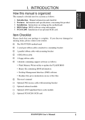
... 5. INTRODUCTION How this product 3. I.INTRODUCTION (Manual/Checklist) I -P55T2P4 User's Manual 1 Introduction: Manual information and checklist 2. PCI-SC200: Installation of the files √ This user's manual Optional PS/2 mouse cable with mounting bracket ...manual is complete. Installation: Instructions on use of an optional SCSI card. Item Checklist Please check that your retailer. √ The P/I-P55T2P4 motherboard √ 2 serial port ribbon cables attached to a mounting bracket √ 1 parallel ribbon cable with mounting bracket Optional infrared module Optional ASUS...
... 5. INTRODUCTION How this product 3. I.INTRODUCTION (Manual/Checklist) I -P55T2P4 User's Manual 1 Introduction: Manual information and checklist 2. PCI-SC200: Installation of the files √ This user's manual Optional PS/2 mouse cable with mounting bracket ...manual is complete. Installation: Instructions on use of an optional SCSI card. Item Checklist Please check that your retailer. √ The P/I-P55T2P4 motherboard √ 2 serial port ribbon cables attached to a mounting bracket √ 1 parallel ribbon cable with mounting bracket Optional infrared module Optional ASUS...
User Manual
Page 8
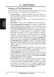
This motherboard: • Easy Installation: Is equipped with I -P55T2P4 User's Manual II. The Japanese "Floppy 3 mode" (3.5" 1.2MB) floppy standard is...which facilitates building of multimedia systems. (For revision compatibility information, please refer to page 18.) • Super Multi-I -P55T2P4 is also supported. 2 P/I /O subsystems. • Error Checking and Correcting (ECC): Using Intel's 430HX PCIset and...level of either an standard PCI card or the ASUS MediaBus Card. • ASUS MediaBus Rev 2.0: Features an expansion slot extension shared with EPP and ECP capabilities.
This motherboard: • Easy Installation: Is equipped with I -P55T2P4 User's Manual II. The Japanese "Floppy 3 mode" (3.5" 1.2MB) floppy standard is...which facilitates building of multimedia systems. (For revision compatibility information, please refer to page 18.) • Super Multi-I -P55T2P4 is also supported. 2 P/I /O subsystems. • Error Checking and Correcting (ECC): Using Intel's 430HX PCIset and...level of either an standard PCI card or the ASUS MediaBus Card. • ASUS MediaBus Rev 2.0: Features an expansion slot extension shared with EPP and ECP capabilities.
User Manual
Page 9
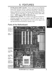
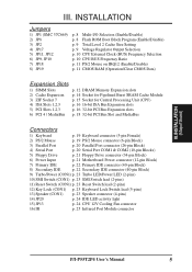
...II. FEATURES • PCI Bus Master IDE Controller: Comes with an on-board PCI Bus Master IDE controller with two connectors that supports the optional ASUS PCI-SC200 SCSI controller cards. BIOS supports IDE CD-ROM boot-up. • Optional IrDA and PS/2: This motherboard supports an optional infrared port ... such as Tape Backup and CD-ROM drives. II. Parts of the Motherboard 3 ISA Slots Flash ROM 3 PCI Slots Super Multi-I/O PCI 4 or ASUS MediaBus 2.0 72-pin SIMM Sockets Intel's 430HX PCIset CPU ZIF Socket 7 L2 Upgrade Cache Expansion Slot On-Board 256KB/ 512KB Pipelined Burst L2 Cache...
...II. FEATURES • PCI Bus Master IDE Controller: Comes with an on-board PCI Bus Master IDE controller with two connectors that supports the optional ASUS PCI-SC200 SCSI controller cards. BIOS supports IDE CD-ROM boot-up. • Optional IrDA and PS/2: This motherboard supports an optional infrared port ... such as Tape Backup and CD-ROM drives. II. Parts of the Motherboard 3 ISA Slots Flash ROM 3 PCI Slots Super Multi-I/O PCI 4 or ASUS MediaBus 2.0 72-pin SIMM Sockets Intel's 430HX PCIset CPU ZIF Socket 7 L2 Upgrade Cache Expansion Slot On-Board 256KB/ 512KB Pipelined Burst L2 Cache...
User Manual
Page 10
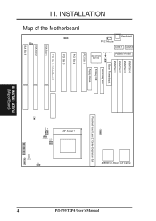
INSTALLATION (Map of the Motherboard JP8 JP18 III. INSTALLATION FOR SMC 37C669 SIMM Slot 4 SIMM Slot 3 SIMM Slot 2 SIMM Slot 1 Board Power Input JP1 Secondary IDE MULTI I/O UMC OR SMC Primary IDE PCI Slot 1 Floppy Drives PCI Slot 2 PCI Slot 3 PCI Slot 4 / MediaBus 2.0 ISA Slot 1 ISA Slot 2 ISA Slot 3 JP19 JP13 Fan Power Pipelined Burst Level 2 Cache Expansion Slot ZIF Socket 7 JP11 JP12 JP9 JP10 JP20 I -P55T2P4 User's Manual Map of Board) JP2 256KB On-Board L2 Cache Parallel Printer COM 1 COM 2 Keyboard PS/2 Mouse P/I R IDE LED JP17 CON1 4 III.
INSTALLATION (Map of the Motherboard JP8 JP18 III. INSTALLATION FOR SMC 37C669 SIMM Slot 4 SIMM Slot 3 SIMM Slot 2 SIMM Slot 1 Board Power Input JP1 Secondary IDE MULTI I/O UMC OR SMC Primary IDE PCI Slot 1 Floppy Drives PCI Slot 2 PCI Slot 3 PCI Slot 4 / MediaBus 2.0 ISA Slot 1 ISA Slot 2 ISA Slot 3 JP19 JP13 Fan Power Pipelined Burst Level 2 Cache Expansion Slot ZIF Socket 7 JP11 JP12 JP9 JP10 JP20 I -P55T2P4 User's Manual Map of Board) JP2 256KB On-Board L2 Cache Parallel Printer COM 1 COM 2 Keyboard PS/2 Mouse P/I R IDE LED JP17 CON1 4 III.
User Manual
Page 11
... Speaker connector (4-pins) 14) JP20 p. 24 IDE LED activity light 15) JP13 p. 24 CPU 12V Cooling Fan connector 16) IR p. 25 Infrared Port Module connector P/I-P55T2P4 User's Manual 5 INSTALLATION (MapofBoard) III. III.
... Speaker connector (4-pins) 14) JP20 p. 24 IDE LED activity light 15) JP13 p. 24 CPU 12V Cooling Fan connector 16) IR p. 25 Infrared Port Module connector P/I-P55T2P4 User's Manual 5 INSTALLATION (MapofBoard) III. III.
User Manual
Page 12
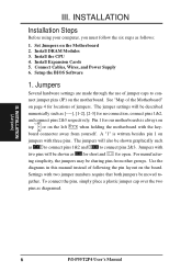
... as to connect pins 1&2 and to con- To connect the pins, simply place a plastic jumper cap over the two pins as follows: 1. INSTALLATION (Jumpers) 6 P/I-P55T2P4 User's Manual INSTALLATION Installation Steps Before using your computer, you must follow the six steps as diagramed. Settings with three pins. Connect Cables, Wires, and Power Supply... Cards 5. A "1" is always on Pin 1 Pin 1 top or on the motherboard. For manufactur- Set Jumpers on the board. III. gether. Use the diagrams in this manual instead of jumper caps to connect pins 2&3.
... as to connect pins 1&2 and to con- To connect the pins, simply place a plastic jumper cap over the two pins as follows: 1. INSTALLATION (Jumpers) 6 P/I-P55T2P4 User's Manual INSTALLATION Installation Steps Before using your computer, you must follow the six steps as diagramed. Settings with three pins. Connect Cables, Wires, and Power Supply... Cards 5. A "1" is always on Pin 1 Pin 1 top or on the motherboard. For manufactur- Set Jumpers on the board. III. gether. Use the diagrams in this manual instead of jumper caps to connect pins 2&3.
User Manual
Page 13
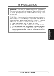
Use a grounded wrist strap before handling computer components. 4. INSTALLATION (Jumpers) P/I-P55T2P4 User's Manual 7 INSTALLATION WARNING: Some pins are clearly separated from static electricity, you should follow some precautions whenever you work on the inside. 2. Place components on a grounded ...
Use a grounded wrist strap before handling computer components. 4. INSTALLATION (Jumpers) P/I-P55T2P4 User's Manual 7 INSTALLATION WARNING: Some pins are clearly separated from static electricity, you should follow some precautions whenever you work on the inside. 2. Place components on a grounded ...
User Manual
Page 14
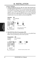
If your motherboard does not use your own Multi-I -P55T2P4 User's Manual INSTALLATION (Jumpers) III. Selections Enable Disable JP1 [1-2] (Default) [2-3] JP 1 1 2 3 Enable (Default) JP 1 1 2 3 Disabled Multi I /O, the following jumper in the Enabled position. Flash ROM Boot Block ...
If your motherboard does not use your own Multi-I -P55T2P4 User's Manual INSTALLATION (Jumpers) III. Selections Enable Disable JP1 [1-2] (Default) [2-3] JP 1 1 2 3 Enable (Default) JP 1 1 2 3 Disabled Multi I /O, the following jumper in the Enabled position. Flash ROM Boot Block ...
User Manual
Page 15
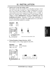
... 512KB. INSTALLATION (Jumpers) JP17 123 STD 3.3V - 3.465V (Default) JP17 123 VRE 3.4V - 3.6V Voltage Regulator Output Selection (STD / VRE) P/I-P55T2P4 User's Manual 9 INSTALLATION 3. Regardless of either 256KB or 512KB. An "ASUS" or "COAST" cache module can be used to upgrade the 256KB version to the CPU. Selections 256KB 512KB JP2 [1-2] [2-3] JP 2 1 2 3 256KB...
... 512KB. INSTALLATION (Jumpers) JP17 123 STD 3.3V - 3.465V (Default) JP17 123 VRE 3.4V - 3.6V Voltage Regulator Output Selection (STD / VRE) P/I-P55T2P4 User's Manual 9 INSTALLATION 3. Regardless of either 256KB or 512KB. An "ASUS" or "COAST" cache module can be used to upgrade the 256KB version to the CPU. Selections 256KB 512KB JP2 [1-2] [2-3] JP 2 1 2 3 256KB...
User Manual
Page 16
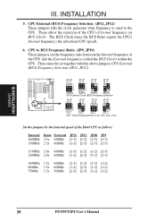
... JP10 JP9 166MHz 2.5x 66MHz [2-3] [1-2] [2-3] [2-3] 150MHz 2.5x 60MHz [1-2] [2-3] [2-3] [2-3] 133MHz 2.0x 66MHz [2-3] [1-2] [1-2] [2-3] 120MHz 2.0x 60MHz [1-2] [2-3] [1-2] [2-3] 100MHz 1.5x 66MHz 90MHz 1.5x 60MHz 75MHz 1.5x 50MHz [2-3] [1-2] [1-2] [1-2] [1-2] [2-3] [1-2] [1-2] [2-3] [2-3] [1-2] [1-2] 10 P/I-P55T2P4 User's Manual CPU to the CPU. These must be set the frequency ratio between the Internal frequency of the CPU and the External frequency (called the BUS...
... JP10 JP9 166MHz 2.5x 66MHz [2-3] [1-2] [2-3] [2-3] 150MHz 2.5x 60MHz [1-2] [2-3] [2-3] [2-3] 133MHz 2.0x 66MHz [2-3] [1-2] [1-2] [2-3] 120MHz 2.0x 60MHz [1-2] [2-3] [1-2] [2-3] 100MHz 1.5x 66MHz 90MHz 1.5x 60MHz 75MHz 1.5x 50MHz [2-3] [1-2] [1-2] [1-2] [1-2] [2-3] [1-2] [1-2] [2-3] [2-3] [1-2] [1-2] 10 P/I-P55T2P4 User's Manual CPU to the CPU. These must be set the frequency ratio between the Internal frequency of the CPU and the External frequency (called the BUS...
User Manual
Page 17
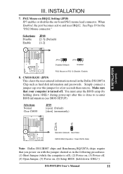
... passwords. See Page 19 for a few seconds then remove. Selections Disable Enable JP18 [2-3] (Default) [1-2] III. You must enter the BIOS setup (by holding down ) P/I-P55T2P4 User's Manual 11 Selections Normal Clear CMOS JP19 [open] (Default) [short] (momentarily) JP JP 19 19 Operation (Default) Clear Data CMOS RAM (Operation / Clear CMOS Data) Note...
... passwords. See Page 19 for a few seconds then remove. Selections Disable Enable JP18 [2-3] (Default) [1-2] III. You must enter the BIOS setup (by holding down ) P/I-P55T2P4 User's Manual 11 Selections Normal Clear CMOS JP19 [open] (Default) [short] (momentarily) JP JP 19 19 Operation (Default) Clear Data CMOS RAM (Operation / Clear CMOS Data) Note...
User Manual
Page 18
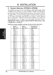
... 24MB 40MB 72MB 136MB 24MB 32MB 48MB 80MB 144MB 40MB 48MB 64MB 96MB 160MB 72MB 80MB 96MB 128MB 192MB 136MB 144MB 160MB 192MB 256MB 12 P/I-P55T2P4 User's Manual
... 24MB 40MB 72MB 136MB 24MB 32MB 48MB 80MB 144MB 40MB 48MB 64MB 96MB 160MB 72MB 80MB 96MB 128MB 192MB 136MB 144MB 160MB 192MB 256MB 12 P/I-P55T2P4 User's Manual

User Manual
Page 19
Modules with more than 24 chips exceed the design specifications of the "Metal Clips". P/I-P55T2P4 User's Manual 13 The SIMM memory modules will cause unreliable operation. With your finger tips, rock the memory module into place. DRAM Memory Installation Procedures: 1. Support Clip ...
Modules with more than 24 chips exceed the design specifications of the "Metal Clips". P/I-P55T2P4 User's Manual 13 The SIMM memory modules will cause unreliable operation. With your finger tips, rock the memory module into place. DRAM Memory Installation Procedures: 1. Support Clip ...
User Manual
Page 20
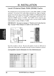
...motherboard you may purchase may install a SIMM cache module of pins are different on page 9 when changes are made to 512KB. An "ASUS" or "COAST" cache module can be upgraded any further. Because the number of either side of Motherboard" for this Motherboard SIMM Cache ...Module 256KB 0KB ASUS CM1 Rev 1.0 No No ASUS CM1 Rev 1.3 No No ASUS CM4 Rev 1.5 No No ASUS CM1 Rev 1.6 Yes No COAST 1.1 No No COAST 1.2 No No COAST 1.3 No No COAST 2.0 Yes Yes COAST 2.1 Yes Yes 14 P/I-P55T2P4 User's Manual III. IMPORTANT: You must set ...
...motherboard you may purchase may install a SIMM cache module of pins are different on page 9 when changes are made to 512KB. An "ASUS" or "COAST" cache module can be upgraded any further. Because the number of either side of Motherboard" for this Motherboard SIMM Cache ...Module 256KB 0KB ASUS CM1 Rev 1.0 No No ASUS CM1 Rev 1.3 No No ASUS CM4 Rev 1.5 No No ASUS CM1 Rev 1.6 Yes No COAST 1.1 No No COAST 1.2 No No COAST 1.3 No No COAST 2.0 Yes Yes COAST 2.1 Yes Yes 14 P/I-P55T2P4 User's Manual III. IMPORTANT: You must set ...
User Manual
Page 21
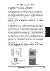
... picture is backwards compatible with the correct orientation as your system and remove its cover. Lever Lock Blank Pentium Processor & ZIF Socket 7 White Dot P/I-P55T2P4 User's Manual 15 Because the CPU has a corner pin for reference only; you turn off your guide. Locate the ZIF socket and open it to insert the...
... picture is backwards compatible with the correct orientation as your system and remove its cover. Lever Lock Blank Pentium Processor & ZIF Socket 7 White Dot P/I-P55T2P4 User's Manual 15 Because the CPU has a corner pin for reference only; you turn off your guide. Locate the ZIF socket and open it to insert the...


