User Manual
Page 9
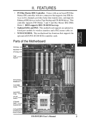
... cable set. • NCR SCSI BIOS: This motherboard has firmware that supports four IDE devices in two channels, provides faster data transfer rates, and supports Enhanced IDE devices such as Tape Backup and CD-ROM drives. FEATURES • PCI Bus Master IDE Controller: Comes with an on-board PCI Bus Master IDE controller with two connectors that supports the optional ASUS PCI-SC200 SCSI controller cards. Parts of the Motherboard 3 ISA Slots Flash ROM 3 PCI Slots Super Multi-I/O PCI 4 or ASUS MediaBus 2.0 72-pin SIMM Sockets Intel's 430HX PCIset CPU ZIF Socket 7 L2 Upgrade...
... cable set. • NCR SCSI BIOS: This motherboard has firmware that supports four IDE devices in two channels, provides faster data transfer rates, and supports Enhanced IDE devices such as Tape Backup and CD-ROM drives. FEATURES • PCI Bus Master IDE Controller: Comes with an on-board PCI Bus Master IDE controller with two connectors that supports the optional ASUS PCI-SC200 SCSI controller cards. Parts of the Motherboard 3 ISA Slots Flash ROM 3 PCI Slots Super Multi-I/O PCI 4 or ASUS MediaBus 2.0 72-pin SIMM Sockets Intel's 430HX PCIset CPU ZIF Socket 7 L2 Upgrade...
User Manual
Page 11
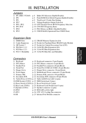
... p. 12 DRAM Memory Expansion slots p. 14 Socket for Pipelined Burst SRAM Cache Module p. 15 Socket for Central Processing Unit (CPU) p. 16 16-bit ISA Bus Expansion slots p. 16 32-bit PCI Bus Expansion slots p. 18 32-bit PCI Bus Slot and MediaBus Connectors 1) Keyboard p. 19 Keyboard connector (5-pin Female) 2) PS/2 Mouse p. 19 PS/2 Mouse connector (6-pin Block) 3) Parallel Port p. 20 Parallel Port connector (26-pin Block) 4) Serial Port p. 20 Serial Port COM1 & COM2 (10-pin Blocks) 5) Floppy Drive p. 21 Floppy Drive connector (34-pin Block) 6) Power Input p. 21 Motherboard Power...
... p. 12 DRAM Memory Expansion slots p. 14 Socket for Pipelined Burst SRAM Cache Module p. 15 Socket for Central Processing Unit (CPU) p. 16 16-bit ISA Bus Expansion slots p. 16 32-bit PCI Bus Expansion slots p. 18 32-bit PCI Bus Slot and MediaBus Connectors 1) Keyboard p. 19 Keyboard connector (5-pin Female) 2) PS/2 Mouse p. 19 PS/2 Mouse connector (6-pin Block) 3) Parallel Port p. 20 Parallel Port connector (26-pin Block) 4) Serial Port p. 20 Serial Port COM1 & COM2 (10-pin Blocks) 5) Floppy Drive p. 21 Floppy Drive connector (34-pin Block) 6) Power Input p. 21 Motherboard Power...
User Manual
Page 12
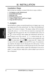
... as diagramed. Connect Cables, Wires, and Power Supply 6. The jumpers will be moved to con- Use the diagrams in this manual instead of jumper caps to - III. INSTALLATION (Jumpers) 6 P/I-P55T2P4 User's Manual Install DRAM Modules 3. Install Expansion Cards 5. The jumper settings will also be sharing pins from yourself. board connector away from other groups. nect jumper pins (JP) on the Motherboard 2. Jumpers with two jumper numbers require that both jumpers be described numerically such as for short and for no connection, connect pins 1&2, and connect pins...
... as diagramed. Connect Cables, Wires, and Power Supply 6. The jumpers will be moved to con- Use the diagrams in this manual instead of jumper caps to - III. INSTALLATION (Jumpers) 6 P/I-P55T2P4 User's Manual Install DRAM Modules 3. Install Expansion Cards 5. The jumper settings will also be sharing pins from yourself. board connector away from other groups. nect jumper pins (JP) on the Motherboard 2. Jumpers with two jumper numbers require that both jumpers be described numerically such as for short and for no connection, connect pins 1&2, and connect pins...

User Manual
Page 22
... a specific device give you removed in use . Setup the BIOS if necessary. 9. Generally an IRQ must be required to use at the same time. 16 P/I-P55T2P4 User's Manual For Windows 95 users, the "Control Panel" icon in the Windows directory to see page 18) which gives you intend to setup your used by parts of ISA cards. Remove your computer will experience problems when those two devices are in step 4. 7. Install the necessary software drivers...
... a specific device give you removed in use . Setup the BIOS if necessary. 9. Generally an IRQ must be required to use at the same time. 16 P/I-P55T2P4 User's Manual For Windows 95 users, the "Control Panel" icon in the Windows directory to see page 18) which gives you intend to setup your used by parts of ISA cards. Remove your computer will experience problems when those two devices are in step 4. 7. Install the necessary software drivers...

User Manual
Page 24
INSTALLATION ASUS MediaBus Card MediaBus allows a cost-efficient solution to maximize the Plug and Play advantages. The add-on this motherboard: • PCI-AS7870 • PCI-AV264CT • PCI-AV868 Fast/Wide SCSI & Audio MediaBus Card PCI Audio & Video MediaBus Card PCI Audio & Video MediaBus Card * All the above Audio features Creative Technology, Ltd. * All the above Video features ATI, Inc. * All the above SCSI features Adaptec, Inc. 18 P/I-P55T2P4 User's Manual The difference between...
INSTALLATION ASUS MediaBus Card MediaBus allows a cost-efficient solution to maximize the Plug and Play advantages. The add-on this motherboard: • PCI-AS7870 • PCI-AV264CT • PCI-AV868 Fast/Wide SCSI & Audio MediaBus Card PCI Audio & Video MediaBus Card PCI Audio & Video MediaBus Card * All the above Audio features Creative Technology, Ltd. * All the above Video features ATI, Inc. * All the above SCSI features Adaptec, Inc. 18 P/I-P55T2P4 User's Manual The difference between...

User Manual
Page 25
...-compatible keyboard. III. Keyboard Connector (5-pin female) This connection is the side closest to the power connector on hard drives and floppy drives. 1. Keyboard Connector (5-pin female) Connector Plug from the first connector. You must also set which connects to the 6 pin block and mounts to enable the PS/2 Mouse. 1 234 58 1 234 58 1: GND 2: DATA 3: NC 4: VCC 5: CLK 8: NC PS/2 Mouse Module Connector P/I-P55T2P4 User's Manual 19 IMPORTANT: Ribbon cables should always be connected with the second drive connector...
...-compatible keyboard. III. Keyboard Connector (5-pin female) This connection is the side closest to the power connector on hard drives and floppy drives. 1. Keyboard Connector (5-pin female) Connector Plug from the first connector. You must also set which connects to the 6 pin block and mounts to enable the PS/2 Mouse. 1 234 58 1 234 58 1: GND 2: DATA 3: NC 4: VCC 5: CLK 8: NC PS/2 Mouse Module Connector P/I-P55T2P4 User's Manual 19 IMPORTANT: Ribbon cables should always be connected with the second drive connector...

User Manual
Page 29
... switch lead (CON1) This allows the user to manually place the system into a suspend mode or "Green" mode where system activity will not cause any problems. May require one or two pushes depending on . See the figure below ) connects to the case-mounted speaker. Keyboard lock switch lead (CON1) This 5-pin connector connects to this connector, "Suspend Switch" in the POWER MANAGEMENT SETUP of the BIOS software should be controlled by settings...
... switch lead (CON1) This allows the user to manually place the system into a suspend mode or "Green" mode where system activity will not cause any problems. May require one or two pushes depending on . See the figure below ) connects to the case-mounted speaker. Keyboard lock switch lead (CON1) This 5-pin connector connects to this connector, "Suspend Switch" in the POWER MANAGEMENT SETUP of the BIOS software should be controlled by settings...

User Manual
Page 31
...-pin ribbon cable, use with the last device on your system user's manual. 4. Connect the power cord into the power supply located on test. If you turn on the chain) c. During power-on system cases that is directed for other standards). This module mounts to a small opening on , hold down the key to enter BIOS setup. INSTALLATION (Connectors) Final Power Connection Procedures 1. Connect the power supply cord into an power outlet that support this feature. External SCSI devices (starting...
...-pin ribbon cable, use with the last device on your system user's manual. 4. Connect the power cord into the power supply located on test. If you turn on the chain) c. During power-on system cases that is directed for other standards). This module mounts to a small opening on , hold down the key to enter BIOS setup. INSTALLATION (Connectors) Final Power Connection Procedures 1. Connect the power supply cord into an power outlet that support this feature. External SCSI devices (starting...
User Manual
Page 32
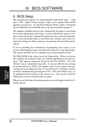
... main program screen will need to download the new BIOS file into the ROM chip as described later, and take note of the configuration settings for specifying the system configuration and settings. Use the Flash Memory Writer utility to call up Setup. When you will appear with the following options: IV. Press the key to configure your motherboard came in particular, the hard disk specifications. Either of the system stores the Setup utility. All computer motherboards...
... main program screen will need to download the new BIOS file into the ROM chip as described later, and take note of the configuration settings for specifying the system configuration and settings. Use the Flash Memory Writer utility to call up Setup. When you will appear with the following options: IV. Press the key to configure your motherboard came in particular, the hard disk specifications. Either of the system stores the Setup utility. All computer motherboards...
User Manual
Page 33
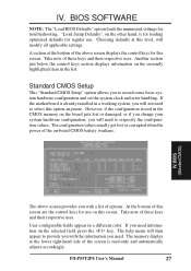
... use . The help menu will then appear to select this level, will modify all applicable settings. User-configurable fields appear in the list. "Load Setup Defaults", on the selected field, press the key. A section at this option anymore. IV. The memory display at the lower right-hand side of this screen are the control keys for regular use on -board CMOS battery weakens. BIOS SOFTWARE NOTE: The "Load BIOS Defaults" option loads the minimized settings for this screen. Choosing defaults...
... use . The help menu will then appear to select this level, will modify all applicable settings. User-configurable fields appear in the list. "Load Setup Defaults", on the selected field, press the key. A section at this option anymore. IV. The memory display at the lower right-hand side of this screen are the control keys for regular use on -board CMOS battery weakens. BIOS SOFTWARE NOTE: The "Load BIOS Defaults" option loads the minimized settings for this screen. Choosing defaults...

User Manual
Page 38
... is Enabled. Setup default setting is Disabled. Boot Up Floppy Seek When enabled, the BIOS will seek the floppy "A" drive one sector per transfer. Boot Up NumLock Status This field enables users to check first the hard disk and then the floppy drive; BIOS (BIOS Features) 32 P/I-P55T2P4 User's Manual IDE HDD Block Mode This field enhances hard disk performance by making multi-sector transfers instead of Read Only to Enabled. The setup default setting for this field is set the two typematic controls listed...
... is Enabled. Setup default setting is Disabled. Boot Up Floppy Seek When enabled, the BIOS will seek the floppy "A" drive one sector per transfer. Boot Up NumLock Status This field enables users to check first the hard disk and then the floppy drive; BIOS (BIOS Features) 32 P/I-P55T2P4 User's Manual IDE HDD Block Mode This field enhances hard disk performance by making multi-sector transfers instead of Read Only to Enabled. The setup default setting for this field is set the two typematic controls listed...
User Manual
Page 39
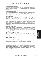
... keystrokes. PCI/VGA Palette Snoop Some display cards that are used for the User Password every time you need to Enable this option otherwise leave this section. IV. The setting Enabled should correct this on them, you to change the video BIOS location from 6 to shadow them specifically. The other expansion cards with installed DRAM of Disabled. BIOS SOFTWARE Typematic Rate (Char/Sec) This field controls the speed at which addresses the ROMs use to 30...
... keystrokes. PCI/VGA Palette Snoop Some display cards that are used for the User Password every time you need to Enable this option otherwise leave this section. IV. The setting Enabled should correct this on them, you to change the video BIOS location from 6 to shadow them specifically. The other expansion cards with installed DRAM of Disabled. BIOS SOFTWARE Typematic Rate (Char/Sec) This field controls the speed at which addresses the ROMs use to 30...

User Manual
Page 41
... to use a different controller card to connect the floppy drives, set this field allows you want to switch drive letter assignments, set this field to the on -board serial ports) IV. This motherboard sums the memory per bank and therefore two modules will give 72bits and the following will be displayed: DRAM are available: "No Swap" and "Swap AB". This works separately from the default of a separate controller card. BIOS (ChipsetFeatures) P/I-P55T2P4 User's Manual 35 (Chipset...
... to use a different controller card to connect the floppy drives, set this field allows you want to switch drive letter assignments, set this field to the on -board serial ports) IV. This motherboard sums the memory per bank and therefore two modules will give 72bits and the following will be displayed: DRAM are available: "No Swap" and "Swap AB". This works separately from the default of a separate controller card. BIOS (ChipsetFeatures) P/I-P55T2P4 User's Manual 35 (Chipset...

User Manual
Page 43
... install Windows including the APM feature. For DOS environments, you CONFIG.SYS. Video Off Option This field determines when to add DEVICE=C:\DOS\POWER.EXE in you need to keep the system time updated when the computer enters suspend mode activated by the BIOS Power Management. This feature turns off ." "User Defined" allows you to your preference. P/I-P55T2P4 User's Manual 37 BIOS SOFTWARE Power Management Setup This "Power Management Setup" option allows you to set power...
... install Windows including the APM feature. For DOS environments, you CONFIG.SYS. Video Off Option This field determines when to add DEVICE=C:\DOS\POWER.EXE in you need to keep the system time updated when the computer enters suspend mode activated by the BIOS Power Management. This feature turns off ." "User Defined" allows you to your preference. P/I-P55T2P4 User's Manual 37 BIOS SOFTWARE Power Management Setup This "Power Management Setup" option allows you to set power...

User Manual
Page 44
... feature does not affect SCSI hard drives. Suspend Switch This field enables or disables the SMI connector on the system case. The system automatically "wakes up" from any IDE hard disk drives in this feature. The "Doze Mode", "Standby Mode" and "Suspend Mode" fields set the CPU speed during each of inactivity. IV. Default setting for Display Power Management System) allows the BIOS to the lead from the enabled IRQ channels. at "Min Saving" after...
... feature does not affect SCSI hard drives. Suspend Switch This field enables or disables the SMI connector on the system case. The system automatically "wakes up" from any IDE hard disk drives in this feature. The "Doze Mode", "Standby Mode" and "Suspend Mode" fields set the CPU speed during each of inactivity. IV. Default setting for Display Power Management System) allows the BIOS to the lead from the enabled IRQ channels. at "Min Saving" after...

User Manual
Page 45
... click its button. P/I-P55T2P4 User's Manual 39 If activity is using, you can enable the Wake-up Event for each slot. All PCI bus slots on the screen set IRQs 3 ~ 15 individually. IRQ3 to IRQ15 You can enable power management for each PCI slot. You can set how IRQ use . BIOS (Plug & Play / PCI) The first four fields on the system use INTA#, thus all installed PCI cards must be set to determine IRQ use is "Auto", which IRQ...
... click its button. P/I-P55T2P4 User's Manual 39 If activity is using, you can enable the Wake-up Event for each slot. All PCI bus slots on the screen set IRQs 3 ~ 15 individually. IRQ3 to IRQ15 You can enable power management for each PCI slot. You can set how IRQ use . BIOS (Plug & Play / PCI) The first four fields on the system use INTA#, thus all installed PCI cards must be set to determine IRQ use is "Auto", which IRQ...
User Manual
Page 46
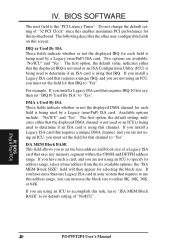
... you have such a card, and you install a Legacy ISA card that IRQ. BIOS (Plug & Play / PCI) 40 P/I-P55T2P4 User's Manual The first option, the default value, indicates either that the displayed IRQ is not used or an ISA Configuration Utility (ICU) is using an ICU, you to "Yes". For example: If you are available: "No/ICU" and "Yes". Do not change the default setting of a Legacy ISA card that channel. ISA MEM Block...
... you have such a card, and you install a Legacy ISA card that IRQ. BIOS (Plug & Play / PCI) 40 P/I-P55T2P4 User's Manual The first option, the default value, indicates either that the displayed IRQ is not used or an ISA Configuration Utility (ICU) is using an ICU, you to "Yes". For example: If you are available: "No/ICU" and "Yes". Do not change the default setting of a Legacy ISA card that channel. ISA MEM Block...
User Manual
Page 48
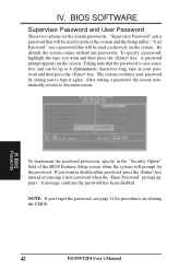
... disable either password, press the key instead of the BIOS Features Setup screen when the system will be used exclusively on the screen. After setting a password, the screen automatically reverts to 8 alphanumeric characters long, type in the "Security Option" field of entering a new password when the "Enter Password" prompt appears. "User Password" sets a password that will prompt for procedures on clearing the CMOS. 42 P/I-P55T2P4 User's Manual The system confirms your password and then press the key. IV. BIOS SOFTWARE Supervisor Password...
... disable either password, press the key instead of the BIOS Features Setup screen when the system will be used exclusively on the screen. After setting a password, the screen automatically reverts to 8 alphanumeric characters long, type in the "Security Option" field of entering a new password when the "Enter Password" prompt appears. "User Password" sets a password that will prompt for procedures on clearing the CMOS. 42 P/I-P55T2P4 User's Manual The system confirms your password and then press the key. IV. BIOS SOFTWARE Supervisor Password...

User Manual
Page 49
... on -board PCI IDE controller supports Enhanced IDE, with two connectors for connecting up to four IDE drives can only install two IDE hard disk drives. BIOS (HardDriveDetect) P/I-P55T2P4 User's Manual 43 When auto-detection is completed, the program automatically enters all entries you want to use another IDE controller that supports four drives, you are not entered in the Standard CMOS Setup screen. BIOS SOFTWARE IDE HDD Auto Detection This "IDE HDD Auto Detection" option detects the parameters of parameters causes the program to accept a set of an IDE hard disk drive, and...
... on -board PCI IDE controller supports Enhanced IDE, with two connectors for connecting up to four IDE drives can only install two IDE hard disk drives. BIOS (HardDriveDetect) P/I-P55T2P4 User's Manual 43 When auto-detection is completed, the program automatically enters all entries you want to use another IDE controller that supports four drives, you are not entered in the Standard CMOS Setup screen. BIOS SOFTWARE IDE HDD Auto Detection This "IDE HDD Auto Detection" option detects the parameters of parameters causes the program to accept a set of an IDE hard disk drive, and...
User Manual
Page 50
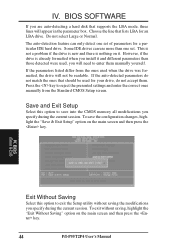
... IDE hard drive. BIOS (LoadSetupDefaults) IV. BIOS (Save & Exit) Exit Without Saving Select this option to enter them . If the parameters listed differ from the Standard CMOS Setup screen. Press the key to exit the Setup utility without saving, highlight the "Exit Without Saving" option on the main screen and then press the key. 44 P/I-P55T2P4 User's Manual Save and Exit Setup Select this option to reject the presented settings and enter the correct ones manually...
... IDE hard drive. BIOS (LoadSetupDefaults) IV. BIOS (Save & Exit) Exit Without Saving Select this option to enter them . If the parameters listed differ from the Standard CMOS Setup screen. Press the key to exit the Setup utility without saving, highlight the "Exit Without Saving" option on the main screen and then press the key. 44 P/I-P55T2P4 User's Manual Save and Exit Setup Select this option to reject the presented settings and enter the correct ones manually...


