
User Manual
Page 2
... of ASUSTeK COMPUTER INC. (hereinafter referred to time without notice. Product Name: P/I-P55T2P4 Product Rev: 2.1 Manual Rev: 2.0 BIOS Version: #401A0-0101 (Displayed on top left during boot-up) Release Date: April 1996 II P/I-P55T2P4 User's Manual ASUS provides this manual "as ASUS) except documentation kept by any kind, either express or implied, including but not...
... of ASUSTeK COMPUTER INC. (hereinafter referred to time without notice. Product Name: P/I-P55T2P4 Product Rev: 2.1 Manual Rev: 2.0 BIOS Version: #401A0-0101 (Displayed on top left during boot-up) Release Date: April 1996 II P/I-P55T2P4 User's Manual ASUS provides this manual "as ASUS) except documentation kept by any kind, either express or implied, including but not...
User Manual
Page 5
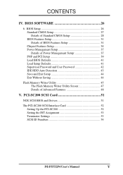
... Setup 31 Chipset Features Setup 34 Power Management Setup 37 Details of Power Management Setup 37 PNP and PCI Setup 39 Load BIOS Defaults 41 Load Setup Defaults 41 Supervisor Password and User Password 42 IDE HDD Auto Detection 43 Save and Exit Setup 44 Exit Without Saving ...44 Flash Memory Writer Utility 45 The Flash Memory Writer Utility Screen 47 Details of Advanced Features 48 V. PCI-SC200 SCSI Card 51 NCR SCSI BIOS and Drivers 51 The PCI-SC200 SCSI Interface Card 52 Setting Up the PCI-SC200 52 Setting the INT Assignment 53 Terminator Settings 53 SCSI...
... Setup 31 Chipset Features Setup 34 Power Management Setup 37 Details of Power Management Setup 37 PNP and PCI Setup 39 Load BIOS Defaults 41 Load Setup Defaults 41 Supervisor Password and User Password 42 IDE HDD Auto Detection 43 Save and Exit Setup 44 Exit Without Saving ...44 Flash Memory Writer Utility 45 The Flash Memory Writer Utility Screen 47 Details of Advanced Features 48 V. PCI-SC200 SCSI Card 51 NCR SCSI BIOS and Drivers 51 The PCI-SC200 SCSI Interface Card 52 Setting Up the PCI-SC200 52 Setting the INT Assignment 53 Terminator Settings 53 SCSI...
User Manual
Page 7
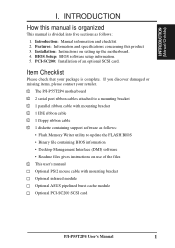
... Checklist Please check that your retailer. √ The P/I . I.INTRODUCTION (Manual/Checklist) I -P55T2P4 motherboard √ 2 serial port ribbon cables attached to update the FLASH BIOS • Binary file containing BIOS information • Desktop Management Interface (DMI) software • Readme files gives instructions on setting up...√ This user's manual Optional PS/2 mouse cable with mounting bracket Optional infrared module Optional ASUS pipelined burst cache module Optional PCI-SC200 SCSI card P/I-P55T2P4 User's Manual 1 BIOS Setup: BIOS software setup information. 5.
... Checklist Please check that your retailer. √ The P/I . I.INTRODUCTION (Manual/Checklist) I -P55T2P4 motherboard √ 2 serial port ribbon cables attached to update the FLASH BIOS • Binary file containing BIOS information • Desktop Management Interface (DMI) software • Readme files gives instructions on setting up...√ This user's manual Optional PS/2 mouse cable with mounting bracket Optional infrared module Optional ASUS pipelined burst cache module Optional PCI-SC200 SCSI card P/I-P55T2P4 User's Manual 1 BIOS Setup: BIOS software setup information. 5.
User Manual
Page 8
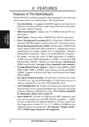
...mode" (3.5" 1.2MB) floppy standard is also supported. 2 P/I -P55T2P4 is carefully designed for the demanding PC user who wants a great many features in a small package. Two floppy drives of either an standard PCI card or the ASUS MediaBus Card. • ASUS MediaBus Rev 2.0: Features an expansion slot extension shared with PCI...ports and one 75-166MHz Pentium CPU on -board 512KB Pipelined Burst SRAM. This motherboard: • Easy Installation: Is equipped with BIOS supports auto detection of hard drives and Plug and Play to make setup of 0KB upgradeable to 256KB or 512KB, on-board 256KB ...
...mode" (3.5" 1.2MB) floppy standard is also supported. 2 P/I -P55T2P4 is carefully designed for the demanding PC user who wants a great many features in a small package. Two floppy drives of either an standard PCI card or the ASUS MediaBus Card. • ASUS MediaBus Rev 2.0: Features an expansion slot extension shared with PCI...ports and one 75-166MHz Pentium CPU on -board 512KB Pipelined Burst SRAM. This motherboard: • Easy Installation: Is equipped with BIOS supports auto detection of hard drives and Plug and Play to make setup of 0KB upgradeable to 256KB or 512KB, on-board 256KB ...
User Manual
Page 9
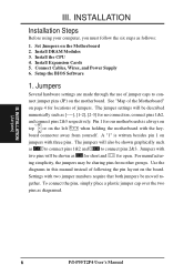
...3 ISA Slots Flash ROM 3 PCI Slots Super Multi-I/O PCI 4 or ASUS MediaBus 2.0 72-pin SIMM Sockets Intel's 430HX PCIset CPU ZIF Socket 7 L2 Upgrade Cache Expansion Slot On-Board 256KB/ 512KB Pipelined Burst L2 Cache P/I-P55T2P4 User's Manual 3 II. This controller supports PIO Modes 3 and 4 ...and Bus Master IDE DMA Mode 2. FEATURES • PCI Bus Master IDE Controller: Comes with an on-board PCI Bus Master IDE controller with two connectors that supports the optional ASUS PCI-SC200 SCSI controller cards. BIOS...
...3 ISA Slots Flash ROM 3 PCI Slots Super Multi-I/O PCI 4 or ASUS MediaBus 2.0 72-pin SIMM Sockets Intel's 430HX PCIset CPU ZIF Socket 7 L2 Upgrade Cache Expansion Slot On-Board 256KB/ 512KB Pipelined Burst L2 Cache P/I-P55T2P4 User's Manual 3 II. This controller supports PIO Modes 3 and 4 ...and Bus Master IDE DMA Mode 2. FEATURES • PCI Bus Master IDE Controller: Comes with an on-board PCI Bus Master IDE controller with two connectors that supports the optional ASUS PCI-SC200 SCSI controller cards. BIOS...
User Manual
Page 12
Setup the BIOS Software 1. nect jumper pins (JP) on the board. Use the diagrams in this manual instead of jumpers. Settings with three pins. Install DRAM Modules 3. board ... for our motherboards is written besides pin 1 on the left when holding the motherboard with two pins will also be moved to con- INSTALLATION (Jumpers) 6 P/I-P55T2P4 User's Manual
Setup the BIOS Software 1. nect jumper pins (JP) on the board. Use the diagrams in this manual instead of jumpers. Settings with three pins. Install DRAM Modules 3. board ... for our motherboards is written besides pin 1 on the left when holding the motherboard with two pins will also be moved to con- INSTALLATION (Jumpers) 6 P/I-P55T2P4 User's Manual
User Manual
Page 14
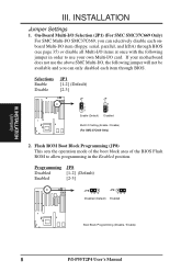
...-I /O SMC37C669, you can selectively disable each item through BIOS (see page 35) or disable all Multi-I/O items at once with the following jumper in order to allow programming in the Enabled position. Selections Enable Disable JP1 [1-2] (Default) [2-3] JP 1 1 2 3 Enable (Default) JP 1 1 2 3 Disabled Multi I -P55T2P4 User's Manual Programming JP8 Disabled [1-2] (Default) Enabled [2-3] JP8...
...-I /O SMC37C669, you can selectively disable each item through BIOS (see page 35) or disable all Multi-I/O items at once with the following jumper in order to allow programming in the Enabled position. Selections Enable Disable JP1 [1-2] (Default) [2-3] JP 1 1 2 3 Enable (Default) JP 1 1 2 3 Disabled Multi I -P55T2P4 User's Manual Programming JP8 Disabled [1-2] (Default) Enabled [2-3] JP8...
User Manual
Page 17
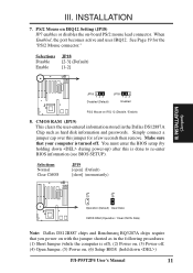
... Enable JP18 [2-3] (Default) [1-2] III. See Page 19 for a few seconds then remove. Simply connect a jumper cap over this is done to re-enter BIOS information (see BIOS SETUP). III. INSTALLATION (Jumpers) JP18 123 Disabled (Default) JP18 123 Enabled PS/2 Mouse on -board PS/2 mouse lead connector. CMOS RAM (JP19) This ... Power off . PS/2 Mouse on IRQ12 Setting (JP18) JP7 enables or disables the on IRQ 12 (Disable / Enable) 8. Make sure that you power on , (6) Setup BIOS (hold down during power-up) after this jumper for the "PS/2 Mouse connector." You must enter the...
... Enable JP18 [2-3] (Default) [1-2] III. See Page 19 for a few seconds then remove. Simply connect a jumper cap over this is done to re-enter BIOS information (see BIOS SETUP). III. INSTALLATION (Jumpers) JP18 123 Disabled (Default) JP18 123 Enabled PS/2 Mouse on -board PS/2 mouse lead connector. CMOS RAM (JP19) This ... Power off . PS/2 Mouse on IRQ12 Setting (JP18) JP7 enables or disables the on IRQ 12 (Disable / Enable) 8. Make sure that you power on , (6) Setup BIOS (hold down during power-up) after this jumper for the "PS/2 Mouse connector." You must enter the...
User Manual
Page 18
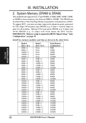
... 24MB 40MB 72MB 136MB 24MB 32MB 48MB 80MB 144MB 40MB 48MB 64MB 96MB 160MB 72MB 80MB 96MB 128MB 192MB 136MB 144MB 160MB 192MB 256MB 12 P/I-P55T2P4 User's Manual System Memory (DRAM & SRAM) This motherboard supports four 72-pin SIMMs of 4MB, 8MB, 16MB, 32MB, or 64MB to form a memory size between...) will work minus the ECC feature. Install two memory modules each time as shown in pairs for all modules. IMPORTANT: Memory setup is required in BIOS Chipset Setup "Auto Configuration" on page 35. INSTALLATION 2.
... 24MB 40MB 72MB 136MB 24MB 32MB 48MB 80MB 144MB 40MB 48MB 64MB 96MB 160MB 72MB 80MB 96MB 128MB 192MB 136MB 144MB 160MB 192MB 256MB 12 P/I-P55T2P4 User's Manual System Memory (DRAM & SRAM) This motherboard supports four 72-pin SIMMs of 4MB, 8MB, 16MB, 32MB, or 64MB to form a memory size between...) will work minus the ECC feature. Install two memory modules each time as shown in pairs for all modules. IMPORTANT: Memory setup is required in BIOS Chipset Setup "Auto Configuration" on page 35. INSTALLATION 2.

User Manual
Page 22
... when those two devices are two types of your used by PCI cards. Carefully align the card's connectors and press firmly. 6. Setup the BIOS if necessary. 9. In an standard design there are 16 IRQs available but not both. System IRQs are then used and free IRQs. Keep...step 4. 7. INSTALLATION 4. Expansion Cards First read your specific card. Generally an IRQ must be required to use at the same time. 16 P/I-P55T2P4 User's Manual You may be exclusively assigned to see page 18) which allows the installation of the system which shows the Interrupt number and address...
... when those two devices are two types of your used by PCI cards. Carefully align the card's connectors and press firmly. 6. Setup the BIOS if necessary. 9. In an standard design there are 16 IRQs available but not both. System IRQs are then used and free IRQs. Keep...step 4. 7. INSTALLATION 4. Expansion Cards First read your specific card. Generally an IRQ must be required to use at the same time. 16 P/I-P55T2P4 User's Manual You may be exclusively assigned to see page 18) which allows the installation of the system which shows the Interrupt number and address...
User Manual
Page 23
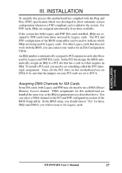
...PNP) specification which IRQs are set something called the INT (interrupt) assignment. INSTALLATION (DMAChannels) P/I-P55T2P4 User's Manual 17 INSTALLATION To simplify this process this motherboard has complied with the BIOS, you wish to reserve for ISA Cards Some ISA cards, both Legacy and PNP ISA cards installed...assigned to INT A. Since all the PCI slots on your vendor for this motherboard use a DMA (Direct Memory Access) channel. In the BIOS setup, you should choose "Yes" for those IRQ's and DMA's you can contact your PCI cards are being used by Legacy cards....
...PNP) specification which IRQs are set something called the INT (interrupt) assignment. INSTALLATION (DMAChannels) P/I-P55T2P4 User's Manual 17 INSTALLATION To simplify this process this motherboard has complied with the BIOS, you wish to reserve for ISA Cards Some ISA cards, both Legacy and PNP ISA cards installed...assigned to INT A. Since all the PCI slots on your vendor for this motherboard use a DMA (Direct Memory Access) channel. In the BIOS setup, you should choose "Yes" for those IRQ's and DMA's you can contact your PCI cards are being used by Legacy cards....

User Manual
Page 26
...used for the included parallel port ribbon cable with mounting bracket. You can enable the parallel port and choose the IRQ through BIOS Setup on an open slot. Connect the ribbon cables to these connectors and mount the bracket to the case on the mounting... bracket will then be available for BIOS configuration of "Onboard Serial Port" COM 1 COM 2 Pin 1 Pin 1 III. INSTALLATION (Connectors) 20 P/I-P55T2P4 User's Manual INSTALLATION 3. Parallel Connector Pin 1 4. The two serial ports on an open slot...
...used for the included parallel port ribbon cable with mounting bracket. You can enable the parallel port and choose the IRQ through BIOS Setup on an open slot. Connect the ribbon cables to these connectors and mount the bracket to the case on the mounting... bracket will then be available for BIOS configuration of "Onboard Serial Port" COM 1 COM 2 Pin 1 Pin 1 III. INSTALLATION (Connectors) 20 P/I-P55T2P4 User's Manual INSTALLATION 3. Parallel Connector Pin 1 4. The two serial ports on an open slot...

User Manual
Page 29
...Lead GND Reset SW GND +5V NC Power LED & GND LOCK Keyboard Lock GND +5V GND Speaker GND Connector SPKR System Case Connections P/I-P55T2P4 User's Manual 23 Wake-up can be instantly decreased to the case-mounted key switch for locking the keyboard for the connector, you do not...12. INSTALLATION (Connectors) III. If you may wish to connect the Power LED from the system case to this connector, "Suspend Switch" in the BIOS but the keyboard will remain constantly lit while the system power is labeled here but the LED will always allow wake-up (the SMI lead...
...Lead GND Reset SW GND +5V NC Power LED & GND LOCK Keyboard Lock GND +5V GND Speaker GND Connector SPKR System Case Connections P/I-P55T2P4 User's Manual 23 Wake-up can be instantly decreased to the case-mounted key switch for locking the keyboard for the connector, you do not...12. INSTALLATION (Connectors) III. If you may wish to connect the Power LED from the system case to this connector, "Suspend Switch" in the BIOS but the keyboard will remain constantly lit while the system power is labeled here but the LED will always allow wake-up (the SMI lead...

User Manual
Page 31
... Your monitor b. The power LED on the front panel of the ribbon cable plug. Follow the next section "BIOS SOFTWARE" for other standards). NC GND +5V IRRX IRTX Front View Back View Infrared Module Connector IRTX +5V GND...7. INSTALLATION (Connectors) Final Power Connection Procedures 1. The system will appear on tests. III. This module mounts to enter BIOS setup. While the tests are made, close the system case cover. 2. After all switches are in the following order: ...may be supplied may have five or ten pins (for instructions. P/I-P55T2P4 User's Manual 25
... Your monitor b. The power LED on the front panel of the ribbon cable plug. Follow the next section "BIOS SOFTWARE" for other standards). NC GND +5V IRRX IRTX Front View Back View Infrared Module Connector IRTX +5V GND...7. INSTALLATION (Connectors) Final Power Connection Procedures 1. The system will appear on tests. III. This module mounts to enter BIOS setup. While the tests are made, close the system case cover. 2. After all switches are in the following order: ...may be supplied may have five or ten pins (for instructions. P/I-P55T2P4 User's Manual 25
User Manual
Page 32
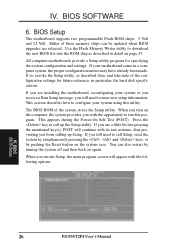
...you are installing the motherboard, reconfiguring your motherboard came in a computer system, the proper configuration entries may have already been made. BIOS (BIOS Setup) 26 P/I-P55T2P4 User's Manual IV. This section describes how to call Setup, reset the system by simultaneously pressing the , and keys, or... the system configuration and settings. If so, invoke the Setup utility, as described in particular, the hard disk specifications. The BIOS ROM of these memory chips can also restart by pushing the Reset button on again. If your system or you receive a Run...
...you are installing the motherboard, reconfiguring your motherboard came in a computer system, the proper configuration entries may have already been made. BIOS (BIOS Setup) 26 P/I-P55T2P4 User's Manual IV. This section describes how to call Setup, reset the system by simultaneously pressing the , and keys, or... the system configuration and settings. If so, invoke the Setup utility, as described in particular, the hard disk specifications. The BIOS ROM of these memory chips can also restart by pushing the Reset button on again. If your system or you receive a Run...
User Manual
Page 33
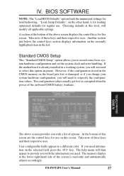
... appear in a working system, you need to record some basic system hardware configuration and set the system clock and error handling. BIOS (StandardCMOS) The above screen displays the control keys for troubleshooting. However, if the configuration stored in the list. IV. At the... NOTE: The "Load BIOS Defaults" option loads the minimized settings for this option anymore. "Load Setup Defaults", on the other hand, is read-only and automatically adjusts accordingly. P/I-P55T2P4 User's Manual 27 Standard CMOS Setup This "Standard CMOS Setup" option allows you with the...
... appear in a working system, you need to record some basic system hardware configuration and set the system clock and error handling. BIOS (StandardCMOS) The above screen displays the control keys for troubleshooting. However, if the configuration stored in the list. IV. At the... NOTE: The "Load BIOS Defaults" option loads the minimized settings for this option anymore. "Load Setup Defaults", on the other hand, is read-only and automatically adjusts accordingly. P/I-P55T2P4 User's Manual 27 Standard CMOS Setup This "Standard CMOS Setup" option allows you with the...
User Manual
Page 34
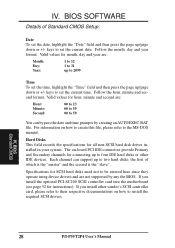
...please refer to 2099 Time To set the date, highlight the "Date" field and then press the page up /page down or +/- BIOS (Standard CMOS) 28 P/I-P55T2P4 User's Manual The on-board PCI IDE connectors provide Primary and Secondary channels for hour, minute and second are: Hour: 00 to 23... drivers and are : Month: Day: Year: 1 to 12 1 to 31 up to the MS-DOS manual. If you install other IDE devices. BIOS SOFTWARE Details of which is the "master" and the second is the "slave". Hard Disks This field records the specifications for instructions). Specifications for month...
...please refer to 2099 Time To set the date, highlight the "Date" field and then press the page up /page down or +/- BIOS (Standard CMOS) 28 P/I-P55T2P4 User's Manual The on-board PCI IDE connectors provide Primary and Secondary channels for hour, minute and second are: Hour: 00 to 23... drivers and are : Month: Day: Year: 1 to 12 1 to 31 up to the MS-DOS manual. If you install other IDE devices. BIOS SOFTWARE Details of which is the "master" and the second is the "slave". Hard Disks This field records the specifications for instructions). Specifications for month...

User Manual
Page 35
... enable auto detection of hard disks on boot-up (see page 29). IV. set it to LBA for a hard disk drive, you specify. BIOS (StandardCMOS) P/I-P55T2P4 User's Manual 29 BIOS SOFTWARE To enter specifications for drives over 528MB that support Logical Block Addressing (LBA) to the configuration you must configure the hard drive...
... enable auto detection of hard disks on boot-up (see page 29). IV. set it to LBA for a hard disk drive, you specify. BIOS (StandardCMOS) P/I-P55T2P4 User's Manual 29 BIOS SOFTWARE To enter specifications for drives over 528MB that support Logical Block Addressing (LBA) to the configuration you must configure the hard drive...

User Manual
Page 36
...or MDA) CGA 40 CGA 80 If you may choose from either: Drive A Drive B Both Disabled (Default) Video Set this field to halt. BIOS (Standard CMOS) 30 P/I-P55T2P4 User's Manual Floppy 3 Mode Support This is normally disabled but you are : 360KB, 5.25 in. 1.2MB, 5.25 in. 720KB, 3.5 in.... 1.44MB, 3.5 in. 2.88MB, 3.5 in a 3.5" diskette. IV. BIOS SOFTWARE Drive A, Drive B These fields record the types of video display card installed in your...
...or MDA) CGA 40 CGA 80 If you may choose from either: Drive A Drive B Both Disabled (Default) Video Set this field to halt. BIOS (Standard CMOS) 30 P/I-P55T2P4 User's Manual Floppy 3 Mode Support This is normally disabled but you are : 360KB, 5.25 in. 1.2MB, 5.25 in. 720KB, 3.5 in.... 1.44MB, 3.5 in. 2.88MB, 3.5 in a 3.5" diskette. IV. BIOS SOFTWARE Drive A, Drive B These fields record the types of video display card installed in your...

User Manual
Page 37
...hard disk against accidental modifications. To load the last set up help menu will cause the system to improve your system. Details of BIOS Features Setup: Virus Warning This field protects the boot sector and partition table of the screen displays the control keys you can either... allow you to halt and display a warning message. P/I-P55T2P4 User's Manual 31 and load the BIOS default values and Setup default values, respectively. Any attempt to write to them will appear to reboot and investigate your ...
...hard disk against accidental modifications. To load the last set up help menu will cause the system to improve your system. Details of BIOS Features Setup: Virus Warning This field protects the boot sector and partition table of the screen displays the control keys you can either... allow you to halt and display a warning message. P/I-P55T2P4 User's Manual 31 and load the BIOS default values and Setup default values, respectively. Any attempt to write to them will appear to reboot and investigate your ...


